© 2019, IRJET | Impact Factor value: 7.211 | ISO 9001:2008 Certified Journal
| Page 895
Numerical Study of Corrugation on Performance of Double
Pipe Heat Exchanger
Manoj Shrivastava
1, Sanjay Kumar Singh
2---***---
ABSTRACT:- The conversion, utilization and recovery of energy in every industrial, commercial and domestic application involve a heat exchange process. Some common examples are steam generation and condensation in power and co-generation plants, sensible heating and cooling of viscous media in thermal processing of chemical, pharmaceutical, and agricultural products, refrigerant evaporation and condensation in air conditioning and refrigeration, gas flow heating in manufacturing and waste heat recovery, air and liquid cooling of engine and turbo- machinery systems, and cooling of electrical machines and electronics devices. Improved heat exchange, over and above that in the usual or standard practice, can significantly improve the thermal efficiency in such applications as well as the economics of their design and operation.
Double pipe heat exchanger (DPHE) or concentric tube heat exchanger is one of the most simple and applicable heat exchanger. This kind of heat exchanger is widely used in chemical, food, oil and gas industries. DPHE having a relatively small diameter and it is easy to fabricate as compared to helical tube, corrugated tube and many more compact types of heat exchanger. Common methods used by the researchers to enhance the heat flow rate are: Active method, Passive method and Compound method. And present work is based on passive method. In the present work numerical study is carried out on DPHE in which hot water is flowing through inner tube where as cold water is flowing through the annulus and hot water to cold water heat exchange is taken into consideration for three different arrangements of DPHE.
i. Plain double pipe heat exchanger
ii. Externally corrugation on inner pipe of heat exchanger
iii. Internally corrugation on inner pipe of heat exchanger
During the study cold water flow rate is kept constant at 50LPH where as hot water flow rate varies from 100LPH to300LPH and comparative study between all the cases has been carried out to know the effect of corrugation on outer and inner surface of inner tube.
Keywords: Corrugation, Effectiveness, Capacity Ratio, Number of transfer units, Heat transfer coefficient, Heat transfer rate.
INTRODUCTION
1. INTRODUCTION:-The conversion, utilization and recovery of energy in every industrial, commercial and domestic application involve a heat exchange process. Some common examples are steam generation and condensation in power and co-generation plants; sensible heating and cooling of viscous media in thermal processing of chemical, pharmaceutical, and agricultural products, Refrigerant evaporation and condensation in air conditioning and refrigeration, gas flow heating in manufacturing and waste heat recovery, air and liquid cooling of engine and turbo- machinery systems, and cooling of electrical machines and electronics devices. Improved heat exchange, over and above that in the usual or standard practice, can significantly improve the thermal efficiency in such applications as well as the economics of their design and operation.
© 2019, IRJET | Impact Factor value: 7.211 | ISO 9001:2008 Certified Journal
| Page 896
1.2 Classification of Heat Exchangers:-
SIMULATION RESULT
Meshing
© 2019, IRJET | Impact Factor value: 7.211 | ISO 9001:2008 Certified Journal
| Page 897
Mesh Domain of Outer corrugated Tube
© 2019, IRJET | Impact Factor value: 7.211 | ISO 9001:2008 Certified Journal
| Page 898
Numerical Result
[image:4.612.96.518.113.492.2](a) (b)
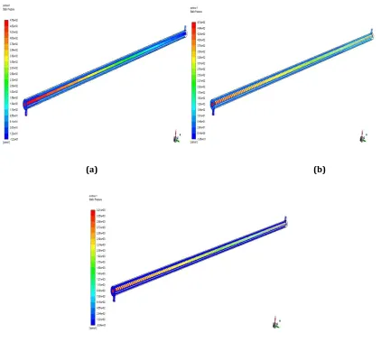
Figure 4.5 Comparison of pressure at 4000 Reynold’s Number for all the three cases.
At 4000 Reynold’s number Figure (a) shows pressure profile for plain tube whereas Figure (b) shows pressure profile for outer corrugated copper tube and, Figure (c) shows pressure for inner corrugated copper tube.
© 2019, IRJET | Impact Factor value: 7.211 | ISO 9001:2008 Certified Journal
| Page 899
[image:5.612.54.557.426.687.2](c)
Figure shows comparison of velocity at 4000 Reynold’s Number for all the three cases.
At 4000 Reynold’s number Figure (a) shows velocity profile for plain tube whereas Figure (b) shows velocity profile for outer corrugated copper tube and, Figure (c) shows velocity for inner corrugated copper tube.
© 2019, IRJET | Impact Factor value: 7.211 | ISO 9001:2008 Certified Journal
| Page 900
(c)
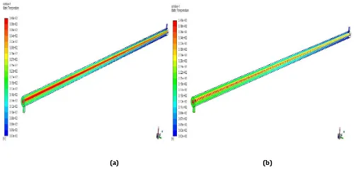
Figure showing comparison of temperature at 4000 Reynold’s Number for all the three cases.
At 4000 Reynold’s number Figure (a) shows temperature profile for plain tube whereas Figure (b) shows temperature profile for outer corrugated copper tube and, Figure (c) shows temperature profile for inner corrugated copper tube.
RESULTS AND DISCUSSION
In this part results obtained from the numerical study for effectiveness, Logarithmic mean temperature difference, overall heat transfer coefficient and heat flow rate is discussed. When cold fluid flow rate is kept constant at 50LPH and hot fluid flow rate varies from 100LPH to 300LPH.
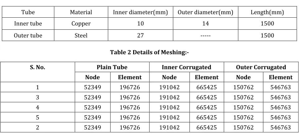
[image:6.612.66.548.438.664.2]Type of tube material used and dimensions are as shown in Table-1 below:-
Table 1 Details of numerical model:-
Tube Material Inner diameter(mm) Outer diameter(mm) Length(mm)
Inner tube Copper 10 14 1500
Outer tube Steel 27 --- 1500
Table 2 Details of
Meshing:-S. No. Plain Tube Inner Corrugated Outer Corrugated Node Element Node Element Node Element
1 52349 196726 191042 665425 150762 546763
3 52349 196726 191042 665425 150762 546763
4 52349 196726 191042 665425 150762 546763
5 52349 196726 191042 665425 150762 546763
© 2019, IRJET | Impact Factor value: 7.211 | ISO 9001:2008 Certified Journal
| Page 901
Table: 3. Plain Copper Tube Heat Exchanger When Cold Water is Fixed at 50 LPH
In counter flow:- Observation table
S.No.
Vol. flow Rate of Hot
Water (LPH)
Thot(inlet)
(o K)
Thot (Outlet)
(o K)
Tcold(inlet)
(oK)
Tcold
(Outlet) (oK)
Average Surface temp of inner tube
(oK)
1. 100 339.65 332.5648 303.15 317.1223 327.731
2. 150 339.65 335.5116 303.15 319.4741 332.1461
3. 200 339.65 336.7136 303.15 320.5182 334.0574
4. 250 339.65 337.3703 303.15 321.1163 335.1706
5. 300 339.65 337.7903 303.15 321.485 335.9108
Table: 4. Outer Corrugated Copper Tube Heat Exchanger When Cold Water is Fixed at 50 LPH
In counter flow:- Observation table
S.No.
Vol. flow Rate of Hot
Water (LPH)
Thot(inlet)
(o K)
Thot (Outlet)
(o K)
Tcold(inlet)
(oK)
Tcold
(Outlet) (oK)
Average Surface temp of inner tube
(oK)
1. 100 339.65 331.5328 303.15 319.5849 325.8458
2. 150 339.65 334.8031 303.15 322.7515 330.7454
3. 200 339.65 336.183 303.15 324.1655 332.9949
4. 250 339.65 336.9497 303.15 324.9713 334.2977
5. 300 339.65 337.4375 303.15 325.4969 335.1532
Table: 5. Inner Corrugated Copper Tube Heat Exchanger When Cold Water is Fixed at 50 LPH In counter flow:- Observation table
S.No. Rate of Hot Vol. flow Water (LPH)
Thot(inlet)
(o K)
Thot (Outlet)
(o K)
Tcold(inlet)
(oK)
Tcold
(Outlet) (oK)
Average Surface temp of inner tube
(oK)
1. 100 339.65 331.6426 303.15 318.9587 327.9557
2. 150 339.65 335.1445 303.15 321.0253 331.5448
3. 200 339.65 336.4609 303.15 322.1425 333.486
4. 250 339.65 337.1753 303.15 322.8088 334.6659
© 2019, IRJET | Impact Factor value: 7.211 | ISO 9001:2008 Certified Journal
| Page 902
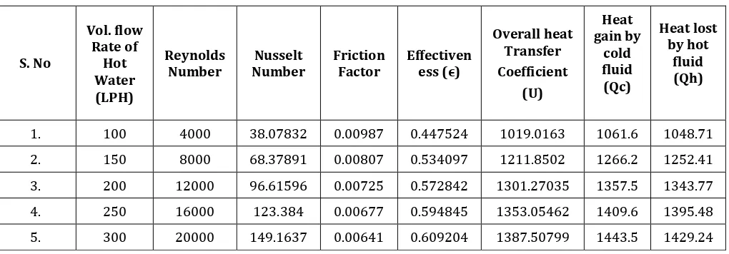
[image:8.612.54.564.305.483.2]Table 6: Results of Plain copper Tube
Table 7: Results of Outer Corrugated copper Tube
S. No Vol. flow Rate of Hot Water (LPH) Reynolds
Number Number Nusselt Friction Factor Effectiveness (ϵ)
Overall heat Transfer Coefficient (U) Heat gain by cold fluid (Qc) Heat lost by hot fluid (Qh)
1. 100 4000 38.07832 0.00987 0.447524 1019.0163 1061.6 1048.71
2. 150 8000 68.37891 0.00807 0.534097 1211.8502 1266.2 1252.41
3. 200 12000 96.61596 0.00725 0.572842 1301.27035 1357.5 1343.77
4. 250 16000 123.384 0.00677 0.594845 1353.05462 1409.6 1395.48
[image:8.612.60.550.518.697.2]5. 300 20000 149.1637 0.00641 0.609204 1387.50799 1443.5 1429.24
Table 8: Results of Inner Corrugated copper Tube
S. No
Vol. flow Rate of Hot Water (LPH)
Reynolds
Number Nusselt Number Friction Factor Effectiveness (ϵ)
Overall heat Transfer Coefficient (U)
Heat gain by cold fluid (Qc)
Heat lost by hot fluid (Qh)
1. 100 4000 47.60049 0.01910 0.435938 968.534147 1034.5 1021.21
2. 150 8000 70.39073 0.01657 0.491743 1044.66991 1164.1 1154.71
3. 200 12000 95.72064 0.01636 0.522289 1103.0112 1236.0 1226.88
4. 250 16000 120.7836 0.01604 0.540498 1139.84838 1278.8 1269.92
5. 300 20000 144.9816 0.01594 0.552438 1164.50641 1307.0 1298.10
S.No Vol. flow Rate of Hot Water (LPH) Reynolds
Number Number Nusselt Friction Factor Effectiveness (ϵ)
Overall heat Transfer Coefficient (U) Heat gain by cold fluid (Qc) Heat lost by hot fluid (Qh)
1. 100 4000 38.67006 0.009928 0.385516 788.359144 902.589 915.3862
2. 150 8000 69.6253 0.008161 0.450379 906.124797 1054.51 1069.338
3. 200 12000 97.6463 0.007219 0.479268 960.168548 1121.95 1138.122
4. 250 16000 124.8331 0.006699 0.495943 992.022691 1160.59 1178.121
© 2019, IRJET | Impact Factor value: 7.211 | ISO 9001:2008 Certified Journal
| Page 903
Fig 5.1 : Graph shows model validation of Reynolds Vs Nusselt number
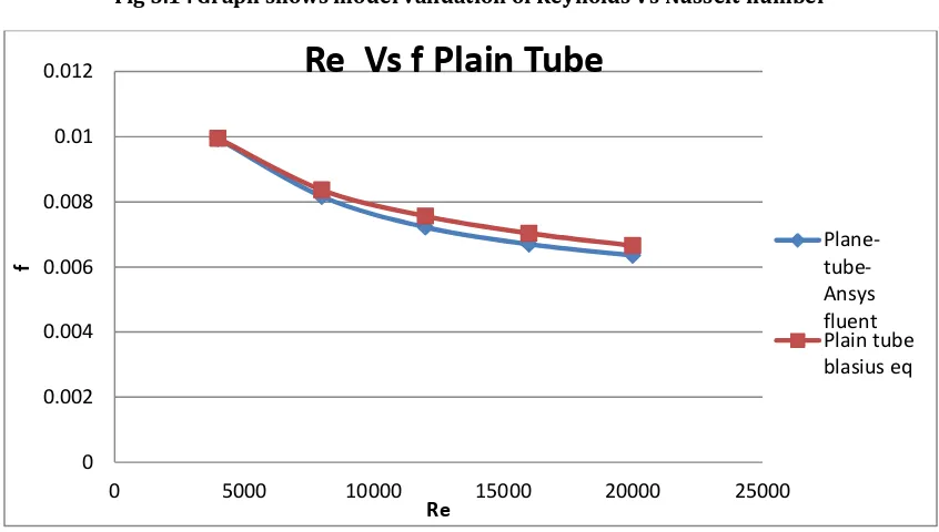
Fig 5.2: Graph shows model validation of Reynolds Vs Friction Factor
To validate the accuracy of the heat transfer system, Nusselt number and friction factor of the plain tube in numerical study are compared with theoretical values as shown in Fig 5.1. The values of Nusselt number and friction factor in the numerical study of plain tube are respectively compared with Dittus-Boelter equation and Blasius equation as shown in Fig.5.2.
0 20 40 60 80 100 120 140 160
0 5000 10000 15000 20000 25000
Nu
Re
Re Vs Nu Plain Tube
Plane-tube-Ansys fluent
Plain tube Dittus boelter Eq
0 0.002 0.004 0.006 0.008 0.01 0.012
0 5000 10000 15000 20000 25000
f
Re
Re Vs f Plain Tube
[image:9.612.94.517.339.579.2]© 2019, IRJET | Impact Factor value: 7.211 | ISO 9001:2008 Certified Journal
| Page 904
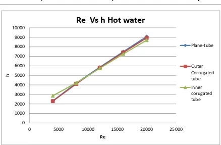
Fig. 5.3: Graph shows Re Vs h for plain, internally corrugated and externally corrugated copper tube.
Fig. 5.4: Graph shows Re Vs Nu for plain, internally corrugated and externally corrugated copper tube.
0 1000 2000 3000 4000 5000 6000 7000 8000 9000 10000
0 5000 10000 15000 20000 25000
h
Re
Re Vs h Hot water
Plane-tube
Outer Corrugated tube
Inner corugated tube
0 20 40 60 80 100 120 140 160
0 5000 10000 15000 20000 25000
Nu
Re
Re Vs Nu Hot water
Plane-tube
Outer corrugated tube
[image:10.612.91.519.380.647.2]© 2019, IRJET | Impact Factor value: 7.211 | ISO 9001:2008 Certified Journal
| Page 905
Variations of Nusselt number with Reynolds number are shown in figure 5.4. As seen from the figure, Nusselt number increases as Reynolds number increases. This is primarily attributed to the increase of turbulent intensity as Reynolds number increases, leading to an amplification of convective heat transfer. At low Reynolds number Nusselt number of internally corrugated tube is higher as compared to externally corrugated tube and plain tube but at high Reynolds number it is lesser than the other two tubes.Fig. 5.5: Graph shows Re Vs Q for plain, internally corrugated and externally corrugated copper tube.
Variation of heat transfer rate with Q Reynolds number are shown in figure 5.5 and it is observed that for all the cases heat transfer rate increases as Reynolds number increases and it is maximum in outer corrugated tube for all values of Reynolds number. Variation of h with Reynold number are as shown in Fig 5.3. As seen from the figure h increases as Re increases. At low Reynold.no h of internally corrugated tube is higher as compared to externally corrugated tube and plain tube but at high Reynold number it is lesser than the other two.
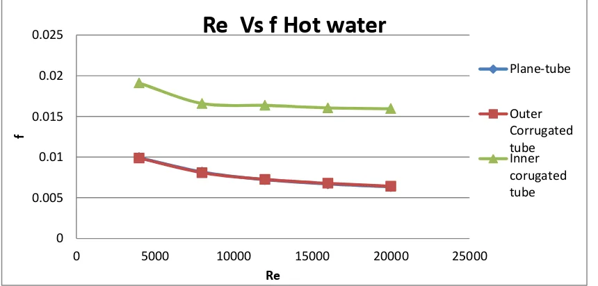
Fig. 5.6: Graph shows Re Vs f for plain, internally corrugated and externally corrugated copper tube.
0 200 400 600 800 1000 1200 1400 1600
0 5000 10000 15000 20000 25000
Qh
o
t
Re
Re Vs Q Heat loss From hot water
Plane-tube
Outer corrugated tube
Inner corrugated tube
0 0.005 0.01 0.015 0.02 0.025
0 5000 10000 15000 20000 25000
f
Re
Re Vs f Hot water
Plane-tube
[image:11.612.94.524.481.687.2]© 2019, IRJET | Impact Factor value: 7.211 | ISO 9001:2008 Certified Journal
| Page 906
Variations of friction factors with Reynolds number are shown in figure 5.6 above. As seen from the figure, friction factors decreases as Reynolds number increases for all the cases. Friction factors for the internally corrugated tube are higher than the externally corrugated tube and plain tube due to surface roughness.Fig. 5.7: Graph shows Re Vs Effectiveness for plain, internally corrugated and externally corrugated copper tube
Variations of effectiveness with Reynolds number are shown in figure 5.7 above. As seen from the figure, effectiveness increases as Reynolds number increases for all the cases. Effectiveness for the externally corrugated tube is higher than the internally corrugated tube and plain tube.
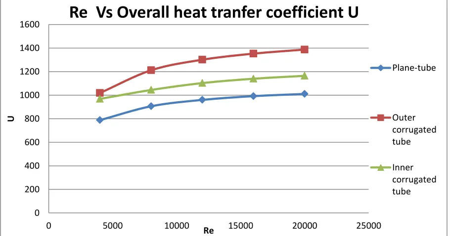
Fig. 5.8: Graph shows Re Vs overall heat transfer coefficient for plain, internally corrugated and externally corrugated copper tube
0 0.1 0.2 0.3 0.4 0.5 0.6 0.7
0 5000 10000 15000 20000 25000
E
Re
Re Vs Effectiveness
Plane-tube
Outer corrugated tube
Inner corrugated tube
0 200 400 600 800 1000 1200 1400 1600
0 5000 10000 15000 20000 25000
U
Re
Re Vs Overall heat tranfer coefficient U
Plane-tube
Outer corrugated tube
[image:12.612.79.534.444.683.2]© 2019, IRJET | Impact Factor value: 7.211 | ISO 9001:2008 Certified Journal
| Page 907
Variations of overall heat transfer coefficient with Reynolds number are shown in figure 5.8 above. As seen from the figure, overall heat transfer coefficient increases as Reynolds number increases for all the cases. Overall heat transfer coefficient for the externally corrugated tube is higher than the internally corrugated tube and plain tube.CONCLUSIONS
Numerical study on characteristics of heat transfer and friction in double pipe heat exchanger for single phase forced convective flow with internally and externally corrugation have been carried out and the following conclusion has been drawn based on the above study.
Internally corrugated tube is more effective as compared to externally corrugated tube and plain tube at low Reynolds
number.
At high Reynolds number externally corrugated tube is more effective than the plain tube and internally corrugated
tube.
Friction factor in case of internally corrugated tube is much larger than the other two tubes for all values of Reynolds
number.
Heat transfer rate, effectiveness and overall heat transfer coefficient of externally corrugated tube is higher than the
other two tubes at all values of Reynolds number.
REFERENCES
MohammodJafari, MousaFarhadi, KouroshSedighi, Thermal Performance Enhancement in a Heat Exchanging Tube via
a Four Lobe Swirl Generator: An Experimental & Numerical Approach, Applied Thermal Engineering 2017, 124, 883-896.
Mustapha Mellal, RedouaneBenzeguir, Djamel Sahel, HouariAmeur. Hydro- Thermal Shell Side Performance
Evaluation of a shell and tube Heat Exchanger under Different Baffles arrangement and Orientation, International Journal of Thermal Sciences, 2017, 121, 138-149.
Mahmoud GalalYehia, Ahmed A.A. Attia, Osama EzzatAbdelatif. Heat Transfer & Friction Characteristics of shell and
tube Heat Exchanger with Multi Inserted Swirl Vanes, Applied Thermal Engineering, 2016, 102, 1481-1491
Wongcharee K, Eiamsa-ard S. Heat Transfer Enhancement by Twisted Tapes with Alternate Axes and Triangular,
Rectangular and Trapezoidal wings , Chemical Engineering and Processing : Process Intensification 2011, 50, 211-219.
Sarada N, Raju S, KalyaniRadha AV, Shyam K. Enhancement of Heat Transfer using Varying Width Twisted Tapes
Inserts, International Journal of Engineering, Science & Technology 2010, 2(6), 107-18
Eiamsa-ard S. Wongcharee K. Eiamsa-ard P. Thianpong C. Thermo-Hydraulic Investigation of Turbulent Flow through
a Round Tube Equipped with Twisted Tapes Consisting of Centre Wings and Alternate Axes, Experimental Thermal & Fluid Science 2010, 34, 1151- 61.
Eiamsa-ard S. Thianpong C. Eiamsa-ard P. Promvonge P., Thermal Characteristics in Heat Exchanger Tube Fitted with
Dual Twisted Tapes Elements in Tandem, InternationalCommunications in Heat and Mass Transfer 2010, 37, 39-46.
Eiamsa-ard S. Thianpong C. Eiamsa-ard P, Promvonge P, Convective Heat Transfer in a Circular Tube with Short Length Twisted Tape Inserts, International Communication in Heat and Mass Transfer 2009, 36, 365-71.