Abstract: This paper will give an insight in to how an Aerodynamics package of a FSAE car is developed as well as the various stages of optimizing and designing the Front wing and Rear wing. The under tray will be explained in a companion paper. The paper will focus on the reasons to use aerodynamic devices, choice of the appropriate wing profile, its 2D and 3D configuration and investigation of the effect of ground proximity for the front wing. Finally, various softwares are implemented to identify the correct configurations for the Front and Rear wing.
Index Terms— ANSYS, CFD, downforce, FSAE, XFLR5
I. INTRODUCTION
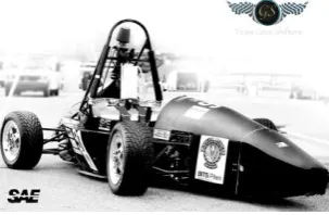
he aim is to create a high downforce aerodynamics package for the FSAE (Formula Society of Automotive Engineers) race car. The objective of the competition is to create an open wheeled 600cc engine car, designed to go up to a top speed of 140Km/hr.
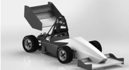
[image:1.595.98.250.516.615.2]As an improvement over the previous FSAE car it was decided to have a complete aerodynamics package for the car. The previous car had a parabolic diffuser which gave good amount of downforce with minimum drag.
Figure 1.Previous year car
Manuscript received March 19, 2016; revised April 17, 2016.
Aravind Prasanth is studying at the Birla Institute of Science and Technology Pilani, Dubai, PO. 345055 UAE (phone: +971 552140408;
e-mail: [email protected]).
Sadjyot Biswal is studying at the Birla Institute of Science and Technology Pilani, Dubai, PO. 345055 UAE ([email protected]).
Azan Barodawala is studying at the Birla Institute of Science and Technology Pilani, Dubai, PO. 345055 UAE ([email protected]).
Aman Gupta is studying at the Birla Institute of Science and Technology Pilani, Dubai, PO. 345055 UAE ([email protected]).
II. AERODYNAMICS
The most important factor in achieving better top speed is the traction due to the tires and this depends upon the normal force. It can be achieved by increasing the mass, however, this takes a toll on the acceleration. Therefore, the option available is to increase the downforce. The drawback of adding aerodynamics package will result in the addition of drag.
It is important to determine how much top speed can be sacrificed without compensating on the track performance.
A. Sacrificial top speed
The acceleration of the car can be expressed as.
(1)
Where
F the force pushing the vehicle Ρ the density of air
Cd the vehicle‟s drag coefficient A the frontal Area of the car m mass of the car
a acc. of the car
Once the max speed of the car is reached the „ma‟ would become zero (a=0). This would imply that
(2) The force can be expressed in terms of power of the car as [3]
(3)
Substituting values of
P as 50kw, this includes the reduction in power due to the 20 mm restrictor from [1].
A as 0.9 m2 and
Cd as 0.85 without wings
Which results in 170.76 km/h being the maximum speed the vehicle can go up to, which is a lot more than the desired speed of 120 km/h for the race track. This implies that the top speed won‟t be limited by the drag force.
Complete Design and Optimization of the
Aerodynamics of a FSAE Car using Solid works
ANSYS & XFLR5
Aravind Prasanth, Sadjyot Biswal, Aman Gupta, Azan Barodawala Member, IAENG
B. Cornering
By using the formula given below the maximum velocity that can be achieved without the aero package during a turn of radius R can be calculated as:
(4) Now with the aerodynamics package with Cl of 1.65, the velocity can be calculated as:
[image:2.595.293.544.148.504.2](5)
Figure 2. Graph btw cornering speed and radius (w & w/o aero)
One of the events in the FSAE completion is SKID PAD which requires the car to trace the figure 8 with a radius of 8.5m. The speed difference calculated using the above formula is approx. 1 km/h, which translates into a gain of approx. 1sec.
III. WING PROFILE SELECTION
To get the maximum output out of the car a high lift and high drag wing profile is used. Using eq. (3) to find max drag for the speed 110 km/h and frontal Area as 1.2 a Cd =1.9 of is obtained which proves that the drag won‟t affect the top speed of the vehicle.
On doing a search for high lift wing profiles in various data bases [5], 6 profiles were selected.
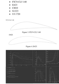
The first preference in selecting the aero foils was higher CL which gives the profile FX74 CL5 140 for the main wing element. It has a high CL of 2.3 at a specific angle of 11°. For the second profile E423, which has a lesser max CL than most of the profiles but a gradual peak in lift makes this
profile more predictable and reliable [2], which makes it suitable for the secondary element of the multi element wing. The manufacturability of the profiles was also taken into consideration while deciding the profiles
These analyses were done using the software XFLR5 for the following profiles.
FX74 CL5 140
E423
CH10
S1223
UI 1720
Figure 3.FX74 CL5 140
Figure 4.E423
Figure 5.XFLR5 analysis
IV. 2DAERO FOIL CONFIGURATION
A. FSAE rules
The FSAE competition‟s rules dictate that [7] T9.2 Location – Front Mounted Devices
T9.2.1 In plain view, no part of any aerodynamic device, wing, under tray or splitter can be:
• Further forward than 700 mm (27.6 inches) forward of the fronts of the front tires
• Wider than the outside of the front tires measured at the height of the hubs.
T9.2.2 When viewed from the front of the vehicle, the part of the front wheels/tires that are more than 250 mm (9.8 inches) above ground level must be unobstructed by any part of the aerodynamic device, with the exception of any vertical surfaces (end plates) less than 25 mm in thickness.
[image:2.595.77.279.181.489.2]T9.3 Location Rear Mounted Devices:
T9.3.1 In plain view, no part of any aerodynamic device, wing, undertray or splitter can be:
• Further rearward than 250 mm (9.8 inches) rearward of the rear of the rear tires
• Further forward than a vertical plane through the rearmost portion of the front face of the driver head restraint support, excluding any padding, set (if adjustable) in its fully rearward position (excluding undertrays).
• Wider than the inside of the rear tires, measured at the height of the hub centerline.
T9.3.2 In side elevation, no part of the rear wing or aerodynamic device (including end-plates) may be higher than 1.2 meters above the ground when measured without a driver in the vehicle
B. Simulation
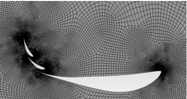
Using the given constrains a box of dimensions 1360x625x125 mm for the front can be created. Similarly, the boundaries for the rear are 1000x840x1200 mm
[image:3.595.313.541.206.453.2]The variables for the ANSYS Fluent 2D analysis were the number of elements, angle of attack and chord length. The mesh count was maintained at around 45,000, which gave considerably accurate values with less computational time.
Figure 6.Mesh for a 3 element wing (front)
The k epsilon model is used for the analysis. This model is used for the speeds and strained flows that are encountered in the FSAE type race cars.
The motion of the road was also taken into consideration. which helps in analyzing the effect of ground proximity on the front wings.
The configurations were then analyzed using different velocities to check for any abnormalities. Simulations which only needed change in parameter values were simulated using the Direct Optimization Module of ANSYS which saved time and brought uniformity into the simulation for an unbiased result.
C. High lift wings
As per the rules of the FSAE competition no part of the aerodynamics package is allowed to move. Hence the best design for a high lift configuration is to use multi-element airfoil design.
The principle behind the multi-element design is that the camber of the wing can be increased to a greater extent as compared to a single element and the flow over the airfoil will be energized due to the lower airfoils [9].
Sr no. alpha chord
(mm)
Downforce (N)
Drag (N)
1 E 1 5.2 55 1183.5 128
E 2 36 11
2 E 1 5.2 55 1582.5 162
E 2 40 11
3 E 1 10.2 34 808.8 144.9
E 2 44 15
4 (gap 11.5)
E 1 5.2 56
1962.7 154
E 2 42 13
5 (gap 5.5)
E 1 5.2 56
1598.3 161.8
E 2 42 13
6 (gap 22)
E 1 5.2 56
1213 149.6
E 2 42 13
7
E 1 0 48
1646.7
182.3
E 2 55 8
E 3 83 8
Figure 7.Results of 2D analysis
[image:3.595.78.270.414.516.2]The 2 element configuration was found to be the best for the Front wing and 3 elements for the rear
Figure 8.Pressure contours
[image:3.595.324.539.604.761.2]Figure 10. Velocity contours
Figure 11. Turbulance
V. 3DANALYSIS
This phase of the design is used for finalizing the aero package which consists of the simulation of the 2D configuration with the endplate to get the total downforce and drag, acting on the vehicle.
• Geometry-The size of the air enclosure was decided as 1 length of the car in front, 3 lengths of the car in the rear, 1 height of the car on top and 1 width of the car on either side. This is done so that the turbulent flow dissipates within the enclosure.
• Mesh- A fine meshing quality with advanced sizing function for both proximity and for curvature was chosen which gave a mesh count of approx. 1,500,000. This will give an error percentage of less than 1.5% error percentage [10]
• Fluent- The simulation was done using k epsilon eq. with RNG selected. The RNG helps gives accurate results for swirls and strained flows. The ground is defined as moving with the same velocity and direction as the inlet air. Since, the main concerns are lift and drag, monitors to analyze them are created.
[image:4.595.330.523.293.398.2]• Post processing- pressure, velocity and turbulence are analyzed to check if any component caused unwanted turbulence.
Figure 12. Enclosure for the simulation of 3D model in ANSYS
Figure 13. Static pressure plot for 3 element wing (rear)
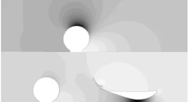
A. Effect of Front wing
While analyzing the results it is important to look at the effect of the front wing since it is the forward most part of the vehicle affecting both downforce produced by the rear wing as well as the drag due to the body and wheels. The front wing reduces the drag by about 10N and lift by about 70N generated by the front wheels
Figure 14. Effect of front wing on front tire (darker the shade, lower the pressure)
[image:4.595.310.541.459.579.2]B. Load Distribution
Figure 15. Static loads acting on the car
It important to keep the forces and moments balanced for safety and good performance. This calculation can be used either to find the location of the force or the magnitude of the force that must be generated.
C. Endplates
Endplates are designed in such a way that they create the least amount of resistance when the car is cornering.
The height of the endplate can be calculated using the formula
[image:4.595.63.284.632.757.2]Figure 16. Vortex generated by the rear endplate
VI. CONCLUSION
The first part of the paper discusses about the method of selection of various components of the aerodynamics package. These methods were then verified using ANSYS Fluent CFD analysis. In the succeeding papers the findings with full-scale wind tunnel testing will be verified.
Figure 17. Rendered image of the complete aerodynamics
ACKNOWLEDGMENT
Firstly, we would like to thank the director of BITS Pilani Dr. Prof. R. N. Saha who has ushered a new light in the university. We would also like thank the Mechanical Department of BITS Pilani Dubai campus for their undying support and special thanks to Dr. Vishal Gangadhar Naranje for his valuable support and guidance throughout the course of the paper.
REFERENCES
[1] Wordley, S.J., and Saunders, J.W., Aerodynamics for Formula SAE: A CFD, Wind Tunnel and On Track Study, SAE Paper 2006-01-0808, 2006
[2] J. Katz, Race Car Aerodynamics, Bentley Publishers, 1995.
[3] McBeath, S., Competition Car Downforce, Haynes Publishers, Somerset, 1998 11. Liebek, R. H., Design of Sub
[4] Ross, J.C., Storms, B.L., and Carrannanto, P.G., Lift-Enhancing Tabs on Multielement Airfoils, Journal of Aircraft, Vol 32, No. 3, pp 649-655, 1995
[5] Airfoil Coordinates Database http://airfoiltools.com/
[6] X. Zhang, J. Zerihan, Aerodynamics of a Double Element Wing in Ground Effect, AIAA Journal, Vol. 41, No. 6, pp 1007-1016, 2003. [7] SAE, 2016 Formula SAE Rules, US Comp Edition, Society of
Automotive Engineers, USA, 2004
[8] Race Car Vehicle Dynamics by William F. Milliken and Douglas L. Milliken.
[9] Smith, A.M.O., “High Lift Aerodynamics,” J. Aircraft, Vol. 15, No. 9, 1978.
[image:5.595.56.273.308.426.2]