Abstract— According to recent statistics, there is an increasing growth in the percentage of older persons in almost every part of the world today is recorded. The rate at which the proportion of older persons increases in the population of developing countries is much faster than what is experienced in developed regions. Specifically, this trend is more predominant in developing economies with relatively much lower level of socio-economic development, particularly in Africa. In response to this, modern technological advances in semiconductor technology and wireless communication can be significantly exploited to drive the economic and social paradigm shifts associated with population ageing towards achieving the Sustainable Development Goals (SDGs) in Africa. In this paper, we designed and implemented a cost-effective smart assistive DTMF home automation system that utilizes a tele-remote circuit to control home appliances via existing cellular communication networks. This system adopted a GSM module as feedback device. Dual Tone Multi Frequency (DTMF) tones generated from keypads of mobile cell phones remotely control home devices and appliances. An integrated DTMF receiver decodes the tones and processes the information to control several devices using a relay switching system with an effective feedback mechanism. The digitally-controlled system overcomes the limited range of infrared and radio remote controls with the aid of available cellular communication systems. Therefore, older people of the populace can be provided with better ease of living at home by minimizing their movement and dependency at affordable cost.
Index Terms—digital control system, DTMF, home automation, population ageing, smart home.
I. INTRODUCTION
ORLD’S population is ageing, considering the increasing percentage of older persons almost in every nation of the world [1]. In recent years, the number of older persons (people that are 60 years old and above) has increased significantly in most countries and regions, and that proportion is expected to grow exponentially in the coming decades. Between 2015 and 2030, the number of people in the world aged 60 years or over is projected to grow by 56 per cent, from 901 million to 1.4 billion, and by 2050, the global population of older persons is projected to more than double its size in 2015, reaching nearly 2.1 billion [2]. Over the next 15 years, the number of older persons in Africa is expected to grow with a projected 64% increase in
the population of people that are 60 years old and above [3]. Meanwhile, smart home automation provide the needed comfort that promote longevity in elderly people, living in their own homes with moderate independence [4].
A smart home can be viewed as an integration system, which takes advantage of a range of techniques such as computers, network communication as well as synthesized wireless technology to connect all indoor subsystems that attach to home appliances and household electrical devices. In this way, smart home technology enables households to effectively centralize the management and services in a home, provide them with all-round functions for internal information exchange and help to keep in instant contact with the outside world. Smart home applications employ microcontrollers to monitor ovens, washing machines, lighting, refrigerators, and HVAC facilities (Heating/Ventilation/Air-Conditioning) with respect to temperature or humidity and to adjust accordingly to meet the home owner’s requirements [5].
Frisardi and Imbimbo [6] expressed a smart home as “a residence equipped with technology that facilitates monitoring of residents to improve quality of life and promote physical independence, as well as to reduce caregiver burden”. Information technology can be leveraged to enhance independence and quality of life for elderly citizens [7]. Morris et al. [8] reported that older adults readily accept smart home technologies, especially if they benefited physical activity, independence and function and if privacy concerns were addressed. As a result of this, the authors suggested that there is a need for further scientific analysis of a range of smart home technologies to promote community living. Comparing the change in functional status in people who had smart technologies installed in their homes with those with no home modifications, functional status and cognition deteriorate in the general elderly population and the use of smart technologies may help to maintain these aspects and encourage ageing in place [9]. Numerous studies [10-26] have confirmed the feasibility of smart home automation for older persons in ageing population.
Manuscript received July 15, 2016; revised August 8. 2016
A. A. Atayero, R. Ozara, S. I. Popoola, and V. O. Matthews are with the Department of Electrical and Information Engineering, Covenant University, Ota, Nigeria (corresponding author’s phone contact: +234-807-886-6304; e-mail: [email protected]).
Development of Smart Assistive DTMF Home
Automation System for Ageing Population
Aderemi A. Atayero, Member, IAENG, Richard Ozara, Segun I. Popoola, Member, IAENG, Victor O. Matthews
In this paper, we designed and implemented a cost-effective smart home automation control system that utilizes a tele-remote circuit to switch home appliances ‘on’ and ‘off’ through existing cellular communication networks, having a GSM module as feedback device. Dual Tone Multi Frequency (DTMF) tones are generated from keypads of mobile cell phones to remotely control home devices and appliances.
An integrated DTMF receiver decodes the tones and processes the information to control several devices using a relay switching system with an effective feedback mechanism. This digitally-controlled system overcomes the limited range of infrared and radio remote controls, with the aid of available cellular communication systems, to provide older people of the populace with better ease of living at home, minimizing their movement and dependency at affordable cost.
II. SYSTEM DESIGN METHODOLOGY
[image:2.595.133.458.283.409.2]The smart home automation system controls electrical devices and appliances through available communication network by dialing their respective pre-configured numbers uniquely designated for each load. This system can be sub-divided into three major units as follows: mobile device (user); DTMF decoder; microcontroller unit; feedback unit; and relay unit. The control system can be operated through home or mobile phones from both within and outside the building. DTMF decoder receives commands sent from the user communication device and generates corresponding digital outputs. A programmable micro-controller, PIC18F452, initializes the four-digit output from the DTMF receiver. The digital output is further processed to actuate the switching mechanism through the relay unit that turns the electrical load either ‘on’ or ‘off’ as requested by the user.
Figure 1: Block Diagram of the Smart Assistive DTMF Home Automation System
Figure 2: Complete Circuit Diagram of the Smart Home Automation Control System Mobile
Device
DTMF Decoder
Micro-
Controller Relay
Unit
Home Appliances Feedback
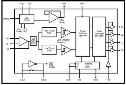
[image:2.595.93.508.476.735.2]A. DTMF Receiver
The full DTMF receiver employed, MT8870, offers low power consumption with accurate data handling capability. The decoder utilizes advanced methods to recognize and unravel each of the 16 DTMF tone sets into a four-bit code. Its building design comprises of a band part filter section of switched capacitors, which divides the high and low tones, taken after by a counting section to confirm the frequency and duration of tones before passing the code to the output bus.
The separation of the low group from high group tones was achieved by making use of the particular DTMF transmission to the inputs of the capacitor band pass filters, the precise bandwidths which matches the frequencies. The actual filtering area incorporates notches at 350 and 440 Hz intended call tone being rejected. Every filtering output is followed by just one switched capacitor filtering area which in turn smoothens the signals.
[image:3.595.59.279.415.564.2]Following the filter section, a decoder which utilizes advanced methods focuses the frequencies of the approaching tones and ensures that they match standard DTMF frequencies. The MT8870 decoder relies on an electronic digital counting method to look for the frequencies with the constrained tones and verify them to correspond to common DTMF frequencies. A complex algorithm is employed to protect against simulation of tones by extraneous signals (such as voice). The algorithm helps to prevent signal jam or interference and noise.
Figure 3: DTMF Receiver Functional Block Diagram
B. Micro-Controller (PIC18F452)
The PIC micro-controller, PIC18F452, operates at a frequency of 40 MHz, and has 32 KB of program memory and flash memory, 1536 byte of data memory (RAM), 16384 byte of program instruction memory, 256 byte of EEPROM memory, 18 interrupt source, 5 input/output ports, timer, 2 capture/compare/PWM modules, MSSP, Addressable USART for serial communication, eight 10-bit input channel A/D converters, programmable low voltage detect. It has some special features such as 100,000 erase/write cycle Enhanced FLASH program memory, typical 1,000,000 erase/write cycle Data EEPROM memory, FLASH/Data EEPROM.
C. GSM Module Configuration
The GSM module acts as the wireless modem, sending and receiving data signal via radio waves. When it is connected to a personal computer (PC), it enables the PC to use the GSM module to communicate over the available mobile network. Communication with the GSM is done through a series of machine instructions used in activating features on an intelligent modem known as AT command set.
The GSM modem is interfaced with the controller by a PNP transistor. In order to interface the GSM with the microcontroller, it is important to ensure that the transmit (Tx) and receive (Rx) pins of the GSM module and the microcontroller are compatible. The maximum input voltage to receive pins of GSM module is 3 Volts and maximum output voltage of transmit (TxD) pins of GSM module is about 2 Volts. The PNP transistor is used to amplify the voltage of the transmit pin of the GSM module from about 2 V to 4-5 V which is a high logic for the receive pin of the PIC microcontroller in order to ensure compatibility.
In this work, we utilized AT+CMGR command to read the message at particular location, where the location number is given as index; AT+CMGS command to send the message; AT+CMGF command to change the message format to PDU or Text mode; AT+CMGL command to access all the list of messages; and AT command to check GSM connection. The SMS message can be up to 160 characters long, where each character is represented by 7 bits according to the 7-bit default alphabets. The GSM/GPRS modem may operate in two SMS modes: the text mode; and the protocol data unit mode. The adopted mode determines the syntax of some of the AT commands and the format of the responses returned after execution. Here, the text mode is utilized. The text mode is just an encoding of the bit stream using specified characters from the alphabet. Alphabets may differ and there are several encoding alternatives when displaying an SMS message. The GSM/GPRS modem will choose a proper encoding, when reading a message, but the application is limited by the set of preset encoding options.
D. System Design Operation
The DTMF signal is provided by MT8870 IC. When the IC detects a valid DTMF input, it sends the appropriate output signal as a four (4) bits binary number for the MCU to read and decode. It also pulses its “StD” pin to signal the presence of a valid code. The relay block is made of two relays and necessary components such as transistors and back EMF suppression diodes. The coil of the relay operates from 5 V. The COM (common) pins of the relays are connected to the live power input while the NO (Normally Opened) pins are taken out to the terminal block as the respective output connection to the loads. This arrangement prevents a load from coming on without activating the appropriate relay.
Figure 4: Flow Chart of the System Design Operation
III. IMPLEMENTATION AND TESTING
The system design was implemented with C programming language. During individual component testing, pins of soldered segments on the Vero-board were checked for dry joints and a multi-meter was used to test for short-circuiting in the connections. Also, the connecting wires of the different components were tested for "continuity" to guarantee that there was no cut-off from the bread-board to the Vero-board.
After soldering of components was done without the major components (MCU, DTMF IC, and GSM Module), continuity test was carried out to ensure that there was no bridging. The next test was to check and confirm proper required voltages at various IC sockets for major components. 5 V typical was confirmed for the PIC18F452 and the LCD module. Also, 4.1 V was required for the GSM module and this was confirmed by using a variable (LM317). After confirming required voltage, major components were then connected.
[image:4.595.55.286.223.441.2]After the implementation of the work, the system was tested by sending different commands (via mobile device) and performing different operations required to activate or deactivate some necessary parts of the system.
Figure 5: System Implementation and Testing
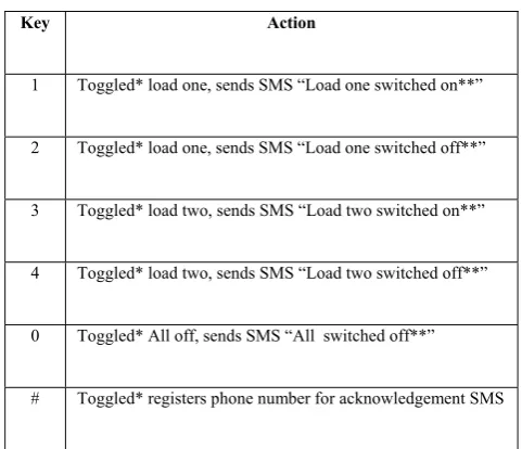
Table 1: System Operation Codes
Key Action
1 Toggled* load one, sends SMS “Load one switched on**”
2 Toggled* load one, sends SMS “Load one switched off**”
3 Toggled* load two, sends SMS “Load two switched on**”
4 Toggled* load two, sends SMS “Load two switched off**”
0 Toggled* All off, sends SMS “All switched off**”
# Toggled* registers phone number for acknowledgement SMS
The PIC18F452 microcontroller was programmed in C language. The code written to manipulate the operation of the microcontroller was simulated using simulation environment provided by MIKRO C PRO. The program was ‘burnt’ onto the microprocessor using a programmer’s kit. HI-TECH compiler was installed together with MPLAB IDE project manager and PICkit2 programming software to program the compiled code into the target microcontroller PIC18F452.
The entire project was packaged in a plastic casing .The packaging has the LCD at the top while the points for the appliances being controlled are at the sides of the casing (outputs).
IV. CONCLUSION
[image:4.595.306.547.259.466.2]existing cellular communication networks, having a GSM module as feedback device, overcomes the limited range of infrared and radio remote controls, with the aid of available cellular communication systems, to provide older people of the populace with better ease of living at their homes with safety and independence.
REFERENCES
[1] United Nations, Department of Economic and Social Affairs, Population Division (2015). World Population Ageing 2015 (ST/ESA/SER.A/390).
[2] World Population Prospects: The 2015 Revision. Available from
http://esa.un.org/unpd/wpp/
[3] Aboderin, Isabella A.G., and John Beard (2015). Older people’s health in sub-Saharan Africa. The Lancet, vol. 385, pp.e9-e11. [4] Behr R, Sciegaj M, Walters R, Bertoty J, Dungan R (2011)
Addressing the housing challenges of an aging population: Initiatives by Blueroof Technologies in McKeesport, Pennsylvania. J Archit Eng 17: 162-169.
[5] Basma M. Mohammad El-Basioni, Sherine Mohamed Abd El-Kader, and Hussein S. Eissa, “Independent Living for Persons with Disabilities and Elderly People Using Smart Home Technology”, International Journal of Application or Innovation in Engineering & Management (IJAIEM), Volume 3, Issue 4, April 2014, pp. 11-28. [6] Frisardi, V.; Imbimbo, B. P. “Gerontechnology for Demented
Patients: Smart Homes for Smart Aging”. J. Alzheimers Dis. 2011, 23, 143–146.
[7] Demiris, G. “Interdisciplinary Innovations in Biomedical and Health Informatics Graduate Education”, Methods Inf. Med. 2007, 46, 63– 66.
[8] Meg E. Morris, Brooke Adair, Kimberly Miller, Elizabeth Ozanne, Ralph Hansen, Alan J. Pearce1, Nick Santamaria, Luan Viegas1, Maureen Long, and Catherine M. Said, “Smart-Home Technologies to Assist Older People to Live Well at Home”, Journal of Aging Science, 2013. http://dx.doi.org/10.4172/jasc.1000101
[9] Tomita M. R., Mann W. C., Stanton K, Tomita A. D., Vidyalakshmi S (2007), “Use of Currently Available Smart Home Technology by Frail Elders: Process and Outcomes,” Top Geriatr Rehabil 23: 24-34. [10] Boll S, Heusten W, Meyer EM, Meis M (2010) Development of a
multimodal reminder system for older persons in their residential home. Inform Health Soc Care. 35: 104-124.
[11] Courtney KL (2008) Privacy and senior willingness to adopt smart home information technology in residential care facilities. Methods Inf Med 47: 76-81. 29.
[12] Courtney KL, Demiris G, Rantz M, Skubic M (2008) Needing smart home technologies: the perspectives of older adults in continuing care retirement communities. Inform Prim Care 16: 195-201.
[13] Davenport RD (2007) Pilot live-in trial at the GatorTech smarthouse. Top Geriatr Rehabil 23: 73-84.
[14] Demiris G, Hensel BK, Skubic M, Rantz M (2008) Senior residents’ perceived need of and preferences for “smart home” sensor technologies. Int J Technol Assess Health Care 24: 120-124. [15] Demiris G, Oliver DP, Dickey G, Skubic M, Rantz M (2008) Findings
from a participatory evaluation of a smart home application for older adults. Technol Health Care 16: 111-118.
[16] Demiris G, Rantz M, Aud M, Marek K, Tyrer H, et al. (2004) Older adults’ attitudes towards and perceptions of “smart home” technologies: a pilot study. Med Inform Internet Med 29: 87-94. [17] Franco GC, Gallay F, Berenquer M, Mourrain C, Couturier P (2008)
Noninvasive monitoring of the activities of daily living of elderly people at home-a pilot study of the usage of domestic appliances. J Telemed Telecare 14: 231-235.
[18] Govercin M, Koltzsch Y, Meis M, Wegel S, Geitzelt M, et al. (2010) Defining the user requirements for wearable and optical fall prediction and fall detection devices for home use. Inform Health Soc Care 35: 177-187.
[19] Johnson JL, Davenport R, Mann WC (2007) Consumer feedback on smart home applications. Top in Geriatr Rehabil 23: 60-72.
[20] Judge S, Robertson Z, Hawley M, Enderby P (2009) Speech-driven environmental control systems - a qualitative analysis of users’ perceptions. Disabil Rehabil Assist Technol 4: 151-157.
[21] Martin S, Nugent C, Wallace J, Kernohan G, McCreight B, et al. (2007) Using context awareness within the ‘Smart home’
environment to support social care for adults with dementia. Technol Disabil 19: 143-152.
[22] Rosenberg L, Kottorp A, Nygard L (2011) Readiness for Technology Use With People With Dementia: The Perspectives of Significant Others. Journal of Applied Gerontology 30: 510-530.
[23] Suryadevara NK, Mukhopadhyay SC (2012) Wireless sensor network based home monitoring system for wellness determination of elderly. IEEE Sensors Journal 12: 1965-1972.
[24] Tang L, Zhou X, Yu Z, Liang Y, Zhang D, et al. (2011) MHS: A multimedia system for improving medication adherence in elderly care. IEEE Systems Journal 5: 506-517.
[25] Van Hoof J, Kort HS, Rutten PG, Duijnstee MS (2011) Ageing-in-place with the use of ambient intelligence technology: Perspectives of older users. Int J Med Inform 80: 310-331.