Abstract—In this paper presents the multi-level inverter which operates at the desired frequency. The desired frequency is designed with the filter on Phase Lock Loop (PLL) controller. This scheme proposed is controlled in the close-loop system by PLL controller and the tracking resonance controller. The multi-level inverter was used to drive the AC motor which changes the speed of the motor instantaneously. The PWM signal of the controller was controlled by PLL controller and designs the band-pass filter by resonance controller. This control scheme is estimated phase and frequency in DQ-transform of the PLL controller with the AC motor characteristic.The speed of the motor was detected the position in the stationary frame. The current of the motor is used for feedback and generating the central frequency for controls the speed of the motor. The PLL controllers were tracked and lock the frequency of the desired signal which is determined high-precision and accuracy of switching sequence in PLL controller for motor control.
Index Terms—Multi-level inverter, PLL controller, Resonance Control, Speed Controller, Band-Pass Filter
I. INTRODUCTION
N recent years, the electrical power systems has been widely investigated for high efficient by sensorless control, directing for the decrease of losses and disturbance. In the industries, the platforms of control are high performance followed the propose control. In this paper, we introduce the dynamic control is used to hold the stator current in the AC motor. The dynamic control of this technique based on the adjusted sequence control was proposed for nonlinear system which control strategies of inverter source have been presented in this paper [1]. The control structure consists of an AC control loop, which is tracking the response of the sinusoidal references and the output voltage of the inverter has commanded to the accurate control in the application. [2].
This purpose technique is used to apply the electrical signals from the encoder. A dc control loop is responsible for the control of the voltage error. The error of the control signal and feedback signal is zero or reached zero on steady-state. The output voltage of the inverter can be achieved the
Manuscript received June 22, 2015; revised July 29, 2015.
1, 2, 3Department of Instrumentation and Control Engineering, Faculty of
Engineering, King Mongkut’s Institute of Technology Ladkrabang, Bangkok 10520, Thailand (Tel: 66–2329–8347: Ext. 102; E–mail: [email protected])
4Department of Electrical Engineering, Faculty of Engineering, Kasem
Bundit University, Bangkok 10250, Thailand (Tel: 66–2320–2777: Ext.1213; E–mail: [email protected])
good waveform. The objective is used to control the AC motor by the resonance controller. A single phase inverter has been investigating the phase control by PLL controller that is employed with the resonance controller. The resonance of power system was suppressed via measuring the speed feedback of the motor [3]. The PLL controller is used to cancel the error of the phase angle which is driving the gate of the inverter. The compensation of the speed is obtained from the resonant mode tuned in the desired frequencies.
This issue presents the implementation and control performance on resonance state. We are focused the dynamic behavior and effects to control the AC motor. The resonant controller make use to estimate the angle on dq-axes algorithms. The harmonic distortion of the multi-level inverter can be removed by a low - pass filter which causes the reduction of the overall control accuracy. In higher-order controlled, the control system has unstable while the resonant controller is used to compensate for loads [4]. The resonant controller improves the phase control signal by the transfer function of the controls. The influence of mechanical resonance can be watched over the behavior of the AC motor and cut the effects by adjusting the frequency in the PLL controller [5]. In the resonance, the frequency will be made decrease the power of the AC motor that using the inertia of the motor increase suddenly. In the power control, the AC loop tracks the current and the DC loop tracks the voltage.
II. METHODDESCRIPTION
A. Speed Control
In this section, we obtain the speed feedback which expresses the pattern of the frequency. In fig.1 (Refered from [6]) shows a model is presented the stability of the closed-loop system. The production of the inverter is measured and transmitted to the AC motor. A typical AC motor control system is included of the motor connected to a load through a junction and a driver [6]. An encoder is attached to the motor shaft to make the closed circuit feedback. The speed of the motor is fed back to the current inverter. The speed signal can adopt by the speed sensor. The current feedback is compensated to according the parameter variation of the load. The control strategies base on the PLL controller and speed controller. The PLL controller is synchronized to the voltage of AC motor to line
Implementation of Resonance in AC Motor
Through Multi-Level Inverter
Based on PLL Technique
K. Phipek
1, V. Tipsuwanporn
2, A. Numsomran
3and A. Charean
4i
V
O V
R
1 12
Q−Q
c
i
O V c
i
dq
T
i
*
o
V θ* ω* *
i
ref
ω
err i
m
i
f
L
f
C
f
L Cf
αβ
Fig.1 Circuit scheme proposed. voltage of the inverter. In this paper, we propose a method to
eliminate electrical resonance by designing the dynamic- control concentrated with feedback [1],[3],[4]. Thus, the electrical resonance can be eliminated by modeling control proposed. In particular, characteristics determine the behavior in the tracking of resonance controller and employ with the PLL controller. The circuit scheme proposed of the motor is showing in fig.1. This structure is proposed for adaptive control. The output filter has influenced the system stability that related the harmonic [2]. In analyze, the inductive loads does not affect the complete filter phase.
B. Resonance Frequency
The output voltage is related to the load by the PLL controller. The control proposes consisting of the PI controllers that are current loop and voltage loop. The current controller is obtained from the reference current in the job of the inverter and the current loss of the AC motor. The resonance controller has been selected to be used in this proposed control that is able to produce the gain control in order to reach zero steady state error. The resonance controller approximates the resonance frequency at a good trade-off between accuracy in tracking and implementation
[4],[7]. This method is important in control design, analysis and synthesis. The resonance frequency tracking can be illustrated in fig.2 and band pass of the resonance controller is showing in fig.3.
ref
ω
m
ω
errω
ω
res* i
Fig.2 Resonance frequency tracking.
error
ω
ω
c±
∆
ω
=
ω
bFig.3 Band pass filter.
In fig.3, the resonance frequency is obtained from between difference the reference frequency and the motor frequency. We are used the capacitor current and the output voltage to controlled the phase and frequency. The phase is locked to be 90°degree at the resonance frequency. However, phase control can be achieved by adding two terms of mathematical models which related to the desired angle
θ
at the resonance frequency [4].
θ
=
∫
ω
*+
(
ω
c±
∆
ω
)
. (1)The resonant controller having the well-known transfer function illustrated in (1) is considered [4].
2 2
2
2
)
(
b b
b
err b
s
s
s
s
G
ω
ζω
ζω
ω
ω
+
+
=
=
. (2)From transfer function (2), we can be obtained the resonant frequency
(
f
res)
as follows [8].
f f res
C
L
f
π
π
ω
2
1
2
=
=
. (3)The motor speed signal obtains from the speed observer that is employed to improve the system. The structure of the speed observer is written in mathematic model as [1].
K
sin(
t
)
dt
di
L
Ri
V
m m m mm
o
=
+
+
ω
ω
. (4)We can be considered the dq model of the two axes in the stationary frame of the ac motor as given by [6]
−
=
b a
q d
V
V
Cos
Sin
Sin
Cos
v
v
θ
θ
θ
θ
III. OPERATIONPRINCIPLES
This section presents the development of the proposed controller for technique controls and there is derived into three sections.
A. Frequency and Speed Close-loop Control
For the stability of the controller is considered an uncertain load. There are several methods to determine the parameters of the performance frequencies (f). The robust stability proof can be derived by using the mathematical equations.
c
ω
ω
ω
c−
∆
ω
c+
∆
ω
Fig.4 Central frequencies and bandwidth.
In fig.4 can be show the bandwidth of the frequency and central frequency that were related with the phase angle. The phase angle was fixed by the PLL controller which is estimated by band-pass filter in the resonance controller. This method provides the ability to control the phase in order to compensate the phase in our system. The desired phase to be compensated is an expression in (6) that directly affect from the magnitude.
The phase angle of resonance
(
ϕ
res)
can be calculated at the resonance frequency is2
π
β
ϕ
res=
+
. (6)The desired phase angle (
θ
) of the frequency at the resonance frequency can be written as
res
t
ϕ
ω
ω
θ
=
+
∠
(
)
. (7)However, all these parameters have to be considered for a proposed control. The magnitude and phase have affected by the behavior of the inverter output power. The magnitude of the resonance frequency is expressed as in (8) [10].
f
res=
f
o(
t
)
=
H
(
j
ω
)
e
jωt. (8)In the trust, the inverter will connect with loads as a resistive load and an induction load which equivalent the AC motor. The output voltage of the inverter will be eliminated the harmonics by the filter which consist of the switching component. The harmonic distortion is presented in the voltage form that operating to establish control in this strategy. When the system has to start in a nonsynchronous condition, the PLL must be performed the operation on the frequency and band-pass.
The resonant compensators are rejecting the asymmetric harmonics, which is presented in a frequency term. The energy flux of the control scheme is absent by the PLL that is interested to control functions. The magnitude and phase
are used in tuning the process and evaluating the control parameters. In order to appropriately design and tune the PLL controller, low-pass filter is behaved with frequencies is then analyzed. The grid frequency is utilized to check the current in an AC motor which obtained from the PLL controller. In fig.5 is showing the block control that is used to compensate both magnitude and phase of the control signals by PLL controller.
Fig.5 Block diagram of control proposed.
The control purposes are able to choose the gain and phase of the controller according to the load condition. The current loop is helped to compensate speed of the motor. The current is a controlled variable two synchronizations during initialization and transients. The current is employed to change the speed motor for this techniques control. A mathematic model based on dq-axes frequency estimation should be obtained suitable phase angle. However, the phase angle of control signals can be estimated in the voltage of dq-transform that is used to calculate the speed of the ac motor [1].
+
+
=
d q
q d
i
i
Lp
r
Lp
r
V
V
0
0
−
+
θ
θ
ω
sin
cos
m m
K
. (9)The loop for compensation of speed is presented, using resonant compensators and the equivalent model of the motor in the dq-axes. The phase error has been reached to cross zero degrees at the resonance frequency [1].
v
err=
V
qsin
θ
+
V
dcos
θ
)
)(
(
r
+
L
ei
q+
i
d−
ω
. (10)B. PLL Controller and Application
v
o=
V
ocos
θ
. (11)θ
sin
o
c
V
i
=
−
. (12)The phase relationship of the capacitor current and the output voltage has the difference phase as
π
/ 2
of the output voltage. In the PLL controller, we can assume the two signals in dq transform asv
qs andv
ds.These variables can be calculated in matrix transform as [6],[9],[10]* *
* *
cos
sin
sin
cos
qe qs
de ds
v
v
v
v
θ
θ
θ
θ
−
=
. (13)The current is connected of the two components between the source and load that is synchronized inverter and AC motor. The current of the inverter is flowing to the loads that connected both others in parallel mode. A frequency and a phase are obtained from a signal that connected between inverter and PLL controller. The investigation was extended to the changing frequency of the inverter in order to function at the resonance frequency. The block diagram of the estimation scheme is shown in fig.6 [1],[5],[6],[9]. The PLL controller can be designed the bandwidth of frequencies with the resonance controller, which is defined by ωPLL. The inverting transform is reversing the voltage of the motor
(
V
a,
V
b)
to the voltage of control signal(
v
d,
v
q)
. Moreover, the speed of the motor is estimated in two current signals which are generated the frequency of the switching devices. The frequency from the PLL controller (ωPLL) can be designed to hold a reaction at specific frequencies.PLL Controller ab
dq
a
v
b
v
*
θ
d
v
q
v
d
i
i
qPLL
ω
θ
θ
s
[image:4.595.348.508.193.247.2]1
Fig.6 The PLL controller and dq transform. The control parameters calculated the frequency and the duty cycle in current loop and voltage loop, respectively. In the PLL controller, the PWM pulses were generated from the DC voltage comparison with the triangle waveform that can be adjusted the frequency and duty cycle. Computation of the control voltage can be received back from the phase angle and amplitude in the PLL controller.
C. Resonance Frequency Analysis
This technique is used a current and a voltage in the LCL model to apply the resonance frequency. On resonant controllers in two dimensions are tuned to get a desired frequency. The phase delay has 90 degrees at the resonant frequency and the phase reference has 0 degrees. The absence of PLL has the advantages the syntheses the control signal. The quadrature signal is obtained by estimating a resonant filter and PLL controller on the output voltage.
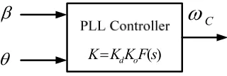
At the resonant frequency of the filters, the input signal was adjusted the frequency to check the PLL controller. The phase angle was estimated by the controller and generated the square wave of control signal at the resonance frequency. The phase angle must be influenced the transient response of the control voltage. The parameters are selecting appropriate control and make small angles. Thus, the tracking error may be made zero. Where
β
is the angle of the current, and θ is the angle of the voltage, and ω are defined the angle and frequency of the grid.β
θ
K
=
K
dK
oF
(
s
)
C
ω
Fig.7 The parameter K in PLL controller. The frequency of tuning can be designed by analyzing the voltage or the current that are presented in the compensation loop in fig.7. The parameter ωC can be chosen according to the selectivity and parameter K can be used in electrical model. The parameter K is used to determine suitable the PWM for switching devices. The employed energy is synchronized by using the
H
(
j
ω
)
presents a resonant mode.)
cos(
ω +
θ
=
v
t
v
o m
=
v
mH
(
j
ω
)
cos(
ω
t
+
θ
)
. (14)i
o=
−
v
msin(
ω +
t
β
)
=
−
v
mH
(
j
ω
)
sin
(
ω
t
+
β
)
. (15)IV. SIMULATIONRESULTS
In this section, we are described the simulation results there are related the output of the AC motor and the inverter. A dc control loop is responsible for the control of the voltage error. The simulation parameters of the inverter were used to estimate the results by Matlab program/simulink. The parameters of the component were used in simulation results are shown in TABLE I.
TABLE I
SIMULATION RESULTS
Symbol Quantity Values
DC
V
DC voltage 50*5=250 Vf
R
Filter resistance 1 Ωf
L
Filter inductance 75 mHf
C
Filter capacitance 100µ
F
m
R
Motor resistance 7.68 Ωm
L
Motor inductance 24.7 mHf
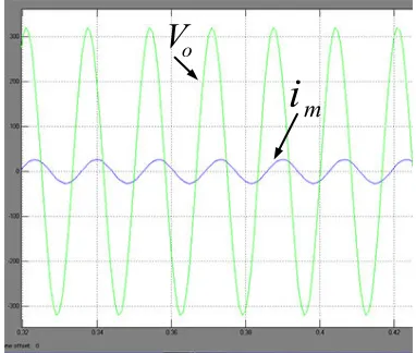
Fundamental frequency 60 Hz [image:4.595.65.282.453.552.2]In fig. 9 is showing the voltage and the current motor at the resonance frequency that is interrupted on time delay. The capacitor current and the motor current are shown in the fig.10.
o
V
m
[image:5.595.81.272.295.425.2]i
Fig. 8 The output voltage and the current motor.
V
i
mFig.9 Time delay on resonance frequency.
c
i
m
[image:5.595.78.271.452.617.2]i
Fig.10 The capacitor current and the motor current. The results of the simulation are shown in fig. 8-10, respectively. In fig. 8 shows the output voltage and the motor current were operated in this propose scheme. The phase of the output voltage has phase lead
π
/
2
of the motor current. This result is affected from the PLL controller that was estimated in dq transform.V. CONCLUSION
This paper presented the multi-level inverter that is controlled at resonance frequency by PLL controller. The PLL controller was designed to operate the bandwidth of the
frequency at resonance state. At resonance frequency, the motor is unable continuous the response in suddenly. The ac motor was detected the speed for control system which is sent to the PLL controller. The proposed strategy uses the phase error and frequency error to tracking the resonance frequency of the control signal. In the PLL controller is discussed in frequency form that was related the current of the inverter. This proposed is derived the utility of PLL controller performed with the LCL component which is used to design the band-pass filter. The band-pass filter was used to track the central frequency of the switching signals. Therefore, the scheme proposed becomes a useful method to obtain a good performance of the sequential switching for the proposed modulation technique.
REFERENCES
[1] K.Balakrishnan, B.Umamaheswari and K.Latha, “Identification of resonance in hybrid stepper motor through measured current dynamics in online for accurate position estimation and control”, IEEE transactions on Industrial Informatics, volume 9, issue 2, pp.1056-1063.
[2] Yiwei Ma, Kai Sun, Xiaonan Lu, Lipei Huang, and Seiki Igarashi, “A grid-connected hybrid cascaded H-bridge inverter”, 2011 International conference on ICEMS, Beijing, China, pp.1-4., 20-23 Aug 2011.
[3] Jianfei Zheng and Yong Feng, “High-order terminal sliding mode based mechanical resonance suppressing method in servo system”, 2nd International symposium on ISSCAA 2008., Shenzhen, China, 10-12 Dec.2008.
[4] Sheng-Ming Yang and Shin-Chuan Wang, “The detection of resonance frequency in motion control systems”, IEEE transaction on Industry Applications, vol.50, no.5, Sep-oct 2014.
[5] Hua Geng, Jianbo sun, Shuai Xiao and Geng Yang, “Medeling and implementation of an all digital phase –lock-loo for grid-voltage phase detection”, IEEE transaction on industrial informatics, volume 9, no.2., May 2013.
[6] V. Tipsuwanporn, A.Charean, A. Numsomran and K. Phipek, A “Single Phase 9-Level Inverter Controlling Based OnPhase Lock Loop Technique”, 2012-12th International conference on ICCAS
2012, Jeju Island, Korea, pp.1497-1502. 17-21 Oct 2012.
[7] Vicente Esteve, Esteban Sanchis-Kilders, Jose Jordan, Enrique J. Dede. Cesar Cases, Enrique Maset, Juan B. Ejea and Agustin Ferreres, “Improving the efficiency of IGBT series-resonant Inverter using pulse density modulation”, IEEE transaction on industrial electronics, vol.58, no.3, March 2011.
[8] Chwei-sen wang, Grant A. Covic and Oskar H. Stielau, “Investigating an LCL load resonant inverter for inductive power transfer applications”, IEEE transactions on power electronics vol.19 no.4, July.2004.
[9] Lajos Torok, Laszlo Mathe and Stig Munk-Nielsen, “Robust control of boost PFC converter using adaptive PLL for line synchronization”, IECON2013-39th Annual conference of the IEEE, Vienna, Austria,
pp.7098-7102, 10-13 Nov.2013.
[10] A. Lidozzi, G.Lo. Calzo, L.Solero and F.Crescimbini, “Multiple resonance controller with load-adaptive phase compensation capabilities”, IECON2013-39th Annual conference of the IEEE,