Human factor influences on effective computer aided
design implementation.
SHORT, Chris.
Available from Sheffield Hallam University Research Archive (SHURA) at: http://shura.shu.ac.uk/20360/
This document is the author deposited version. You are advised to consult the publisher's version if you wish to cite from it.
Published version
SHORT, Chris. (2001). Human factor influences on effective computer aided design implementation. Doctoral, Sheffield Hallam University (United Kingdom)..
Copyright and re-use policy
U l r m m hjU S, HOWARD STREET
SHEFFIELD SI 1WB
101 6 8 7 823 0
i
S'? vm.
Fines
are
charged
at
50
p
per
ProQuest Number: 10701006
All rights reserved
INFORMATION TO ALL USERS
The quality of this reproduction is dependent upon the quality of the copy submitted.
In the unlikely event that the author did not send a com plete manuscript and there are missing pages, these will be noted. Also, if material had to be removed,
a note will indicate the deletion.
uest
ProQuest 10701006
Published by ProQuest LLC(2017). Copyright of the Dissertation is held by the Author.
All rights reserved.
This work is protected against unauthorized copying under Title 17, United States C ode Microform Edition © ProQuest LLC.
ProQuest LLC.
789 East Eisenhower Parkway P.O. Box 1346
HUMAN FACTOR INFLUENCES ON EFFECTIVE
COMPUTER AIDED DESIGN IMPLEMENTATION
Chris Short
B.Sc, M.Sc, Cert Ed, CEng, MIMechE, MIED
A thesis submitted in partial fulfilment of the requirements of Sheffield Hallam University for the degree of Doctor of Philosophy
ABSTRACT
Computer Aided Design (CAD) has the capability to influence a company's competitiveness in terms of quality, flexibility and cost effectiveness of design. Consequently, the opportunities provided by the efficient and effective use of CAD techniques are vital to a company's operational and business success.
The aims of this research have been to;
1 Ascertain and identify the contribution and relevance of human factor and technological issues within a successful CAD implementation methodology.
2 Develop a human factor understanding which, when incorporated into an implementation methodology aids the introduction of CAD technology and increases the likelihood of realising opportunities.
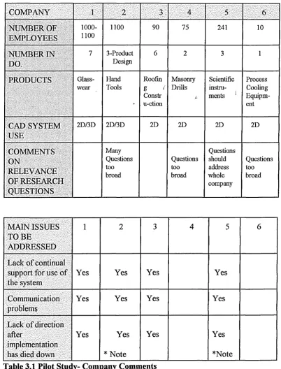
The initial research is based on a review of the literature on CAD and a pilot study of six companies employing CAD. This identifies the mix of issues involved during
implementation as being, Technical, Organisational and Human. It also highlights the main problems experienced by companies as a function of the levels of Support, Direction and Communication.
The above issues have been incorporated into a CAD introduction framework based on quality criteria. The results of this initial stage of the research have been substantiated by in-depth case studies of three companies, in various stages of CAD adoption and "Best Practice" activities have been identified for each area of the framework and related to the overall performance of the companies.
To widen the scope of the investigation and provide more evidence, the framework was then employed in the in-depth analysis of six further case studies. These identified CAD support as playing a key role in maximising CAD potential.
CONTENTS PAGE
ABSTRACT ii
CONTENTS Hi
LIST OF TABLES vii
LIST OF FIGURES x
LIST OF ABBREVIATIONS xv
ACKNOWLEDGEMENTS xvii
DECLARATION xviii
1.0 INTRODUCTION 1
1.1 Aims of the Research 1
1.2 Computer System Development 2
1.3 CAD Applications 5
1.3.1 The Design Process 5
1.3.2 Types of 3D Modellers 7
1.3.3 Fields of Application 11
1.4 Thesis Structure 12
2.0 LITERATURE SURVEY 14
2.1 Introduction 14
2.2 Human Factors 22
2.3 The Need for CAD 27
2.4 Implementation Strategies 30
2.5 Literature Review Summary 40
3.0 RESEARCH METHODOLOGY 42
3.1 Introduction-Social Research Methodology 42
3.1.1 Fieldwork 44
3.1.2 Conclusion 46
3.2 Overall CAD Implementation Research Methodology
Structure 46
3.3 Initial Pilot Study Methodology 50
3.4 Pilot Study Results 51
3.5 Case Study Research Methodology 5 8
3.6 Framework for Initial Case Study
Evaluation-Companies A, B & C 59
3.7 Framework for Selecting Companies for In-depth Case Study 62
3.7.1 Initial Case Studies 63
4.0 INITIAL CASE STUDY RESULTS FOR COMPANIES "A”, ” B"
and "C" 70
4.1 Introduction 70
4.2 Initial Case Study Evaluation Rating System 72
4.3 Initial Case Study Results- Company CAD Operation and Support 75
4.3.1 Case Study "A" 75
4.3.2 Case Study "B" 83
4.3.3 Case Study "C" 91
4.4 Discussion of Initial Case Study Results 99
4.5 Research Development 109
5.0 FURTHER CASE STUDIES- CAD OPERATION AND
SUPPORT 112
5.1 Introduction 112
5.2 Case Study "D" 114
5.3 Case Study "E" 119
5.4 Case Study "F" 128
5.5 Case Study "G" 134
5.6 Case Study "H" 142
5.7 Case Study "I" 149
6.0 DISCUSSION OF CASE STUDY RESULTS 159
6.1 Introduction 159
6.2 Discussion of Further Case Studies 159
6.3 Summary Characteristics of All Nine Case Study Companies-
Companies A to I 169
6.3.1 Companies Exhibiting Strong Support Structures 170
6.3.2 Companies Exhibiting Less Strong Support Structures 171
6.4 Generic Themes Suggested by The Case Studies 172
6.5 The Support Model 173
6.6 Propositions 175
7.0 NATIONAL (UK) CAD SURVEY 177
7.1 Target Companies 178
7.1.1 Target Areas- Sampling Method 179
7.1.2 Target Companies-Sampling Size 180
7.1.3 Identification of Target Companies 181
7.2 Questionnaire Design 183
7.2.1 Testing of The Questionnaire 191
7.2.2 Data Entry and Questionnaire Testing 194
8.0 NATIONAL SURVEY RESULTS 197
8.1 Introduction 197
8.2 Presentation of Results 201
8.2.1 Detailed Analysis 203
8.2.3 Initial Company Information 206
8.2.4 The Design Process 213
8.2.5 CAD Introduction and Development 224
8.2.6 Support Structures for CAD 253
8.2.7 Training 258
8.2.8 Impact of CAD on the Company 268
9.0 ANALYSIS OF UK NATIONAL SURVEY RESULTS 279
9.1. Initial Information About Companies 279
9.2 The Design Process 281
9.3 CAD Introduction and Development 285
9.4 Support Structures for CAD 297
9.5 Training 312
9.6 Impact of CAD on the Company 326
9.6.1 Problems experienced by companies 328
9.6.2 Moving Forward With CAD 331
9.7 Summary 333
10.0 DISCUSSION OF RESEARCH RESULTS 335
10.1 Introduction 335
10.2 Definition of the Model 336
10.3 National Survey 339
11.0 CONCLUSIONS AND RECOMMENDATIONS FOR FURTHER
WORK 343
11.1 Introduction 343
11.2 Case Studies 343
11.3 Postal Survey 344
11.4 A Support Model 346
11.5 Summary of Research 347
11.6 Recommendations for Further Work 348
REFERENCES 351
APPENDICES: Appendix A:
Al. Pilot Study Research Questions i
A2. Pilot Study Covering Letter V
Appendix B
Bl. Case Study "B" Progress vi
B2. Initial Case Study Company Rating System vii
Appendix C
Cl. Types of CAD Systems Employed By Companies Taking Part In The
C2. Company Comments Regarding Organisational Changes As A
Result Of CAD-2D and 3D Users xii
C3. Company Comments Regarding Forms Of Resistance To CAD xiv
C4. Company Comments Regarding The Effect Of CAD On Morale And
Relationships In The Department xiv
C5. Company Comments Regarding Difficulties Experienced By Users
Of 3D CAD xvii
C6. Comments From Companies Stating The Main Problems Experienced By Staff In Becoming Effective Users Of The CAD Systems xviii Cl. Company Comments Regarding Solutions Needed To Overcome Staff
Difficulties With 3D xxi
C8. Main Problems Experienced by Companies Who Are Not Achieving
All They Hoped From CAD xxii
C9. Company Perceptions of Activities Required to Move Forward and
Obtain Even Greater Benefit with CAD xxiii
Appendix D
D1. Percentage Responses to National Survey Questionnaire Questions xxvii
D2. Covering Letter for National Survey xxxvi
D3. How "SNAP" Builds Tables of Results xxxvii
Appendix E
El. How Chi-Squared Test Works from "SNAP" xxxix
LIST OF TABLES PAGE
Table 2.1 Model for effective CAD implementation 33
Table 3.1 Pilot study- Company comments 53
Table 4.1 Comparison of case study companies A, B and C; Markets,
sizes and activities 71
Table 4.2 Typical "comments writing" table employed for evaluating
company performance 72
Table 4.3 Structure of numerical evaluation system 73
Table 4.4 Summary aspects of company activities-Leadership 100
Table 4.5 Summary aspects of company activities-Planning 101
Table 4.6 Summary aspects of company activities-Support for use of
the technology 102
Table 4.7 Summary aspects of company activities-Human
development 103
Table 4.8 Summary aspects of company activities-Reviewing 104
Table 4.9 Summary aspects of company activities-Participation 104
Table 4.10 Summary aspects of company activities-Problem solving 105
Table 4.11 Summary aspects of company activities-Quality focus 105
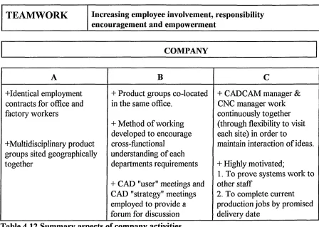
Table 4.12 Summary aspects of company activities-Teamwork 106
Table 4.13 Summary aspects of company activities- 109
Table 5.1 Comparison of further case study companies D to I; Markets,
sizes and activities 113
Table 6.2 Summary characteristics of further case studies-Human
development 161
Table 6.3 Summary characteristics of further case studies-Teamwork 162
Table 6.4 Summary characteristics of further case studies-Planning 163
Table 6.5 Summary characteristics of further case studies-Reviewing 164
Table 6.6 Summary characteristics of further case studies-Participation 165
Table 6.7 Summary characteristics of further case studies-Leadership 166
Table 6.8 Summary characteristics of further case studies-Quality 167
Table 6.9 Summary characteristics of further case studies-Impact on
the company 168
Table 6.10 Strong and weak aspects of company activities 170
Table 8.1 Logical expressions used to filter responses of specific groups 199
Table 9.1 Percentage of user groups employing some form of analysis 282
Table 9.2 Duration that companies have been employing CAD and the
current system 284
Table 9.3 Statistical relationship between investment per seat in CAD by
users and achievements from CAD 287
Table 9.4 Statistical relationship between change in organisational
structure and achievements with CAD 291
Table 9.5 Statistical comparison of CAD achievements with resistance
to technology by all users 292
Table 9.6 Statistical comparison of CAD achievements with resistance
to the technology by 2D only users 293
activities 304
Table 9.8 Average support ratings 305
Table 9.9 Numbers of companies employing the given approach to
training 312
Table 9.10 Indication that training is not a governing factor in satisfaction 317
Table 9.11 Relationship between length of training and satisfaction with CAD 318
Table 9.12 Average investment in training as a percentage of capital
investment 322
Table 9.13 Average numbers of products introduced by user groups 327
LIST OF FIGURES PAGE
Figure 1.1 Wireframe model of a bracket base 8
Figure 1.2 Surface model of a plastic bottle 9
Figure 1.3 Solid model of bracket base 10
Figure 2.1 Results of search on the INSPEC computer database 15/16
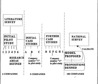
Figure 3.1 Overall CAD implementation research methodology
structure 49
Figure 3.2 Themes suggested by the literature review and pilot study 55
Figure 3.3 Technical, organisational and human issues in CAD
implementation 57
Figure 4.1 Wheel used to provide visual indication of company
performance 75
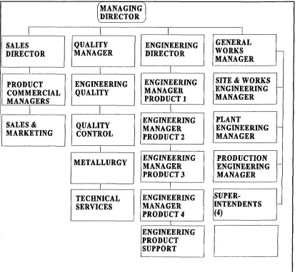
Figure 4.2 Post CAD organisational structure for company "A" 76
Figure 4.3 Organisational structure for engineering at company "A" 77
Figure 4.4 Support structure for company "A” 80
Figure 4.5 Organisational structure for company "B" 84
Figure 4.6 Support structure for company ”B1' 87
Figure 4.7 Typical cubic spline 89
Figure 4.8 Organisational structure for company "C" 92
Figure 4.9 Support structure for company "C" 96
Figure 4.10 Performance of company "A" in relation to research
framework 107
Figure 4.11 Performance of company "B" in relation to research
Figure 4.12 Performance of company "C" in relation to research
framework 108
Figure 5.1 CAD support structure for company "D" 117
Figure 5.2 Organisational structure for company "E" 120
Figure 5.3 Engineering product groups for company "E" 121
Figure 5.4 CAD support structure for company "E" 125
Figure 5.5 CAD support structure for Company "F" 132
Figure 5.6 Organisational structure for company "G" 134
Figure 5.7 Organisational structure of design department for
company "G" 135
Figure 5.8 Organisational structure for company "H" 143
Figure 5.9 Valves organisational structure for company "H" 143
Figure 5.10 CAD support structure for company "H" 147
Figure 5.11 I.T. support structure for company "I" 153
Figure 5.12 CAD support structure for company "I" 155
Figure 6.1 Themes presented by the case studies 172
Figure 6.2 Proposed support model for maximising CAD success 174
Figure 7.1 Numbers of companies targeted in each product group 182
Figure 7.2 Pre-defining response variables during questionnaire
design 188
Figure 7.3 Showing all answers are valid responses to literal questions 189
Figure 7.4 Examples of "Grid" employed with multi-choice questions 190
Figure 7.5 Screen shot illustrating the manual input of data to questionnaire
197 198 202 203 205 207 209 211 213 216 218 220 222 225 227 229 231 233 235 237 239 241 Typical charts and tables produced by SNAP
Drop down dialog box for results definition
Companies in sample
Percentage response rates to survey questionnaire by different
product groups
General company information
Initial information about companies
Range of activities undertaken in user companies
Organisational structures employed by companies
Type of work performed on a regular basis
Percentage of work carried out manually on the drawing board
The design process- number of drawing boards employed
Percentage of work undertaken using CAD
Investment in CAD- numbers of seats
Length of time companies have been employing CAD
Length of time companies have been employing their current
CAD system
Jobs for which the current system is used
Approximate investment in CAD (excluding training)
Average investment per CAD seat
Reasons companies needed the current CAD system- Productivity
Reasons companies needed the current CAD system-New work
Reasons companies needed the current CAD system-Competition
Figure 8.23 Reasons companies needed the current CAD system-Tooling 243
Figure 8.24 Reasons companies needed the current CAD system-Customer
response 245
Figure 8.25 Organisational structure changes since implementing CAD 247
Figure 8.26 Changes in working practices due to CAD implementation 249
Figure 8.27 Resistance to the technology by users 251
Figure 8.28 The organisational structures employed by companies for
supporting CAD 254
Figure 8.29 Company ratings of activities supported by internal support 256
Figure 8.30 Types of training employed by companies 259
Figure 8.31 Amount of time spent on training to use the CAD system 261
Figure 8.32 Amount invested by companies on training 263
Figure 8.33 Length of time after initial training before staff* could use
the system effectively 265
Figure 8.34 Percentages of companies using 3D reporting difficulties
with the technology 267
Figure 8.35 Impact of CAD on the company- achievement of CAD
aspirations 269
Figure 8.36 Impact of CAD on company business 271
Figure 8.37 Impact of CAD on the company-number of new products
introduced during the last year 273
Figure 8.38 Impact of CAD on the company-number of new products
Figure 8.39 Operational benefits seen by companies as a direct result of
CAD implementation 277
Figure 9.1 Original company needs for CAD 289
Figure 9.2 Numbers of companies expressing levels of satisfaction with CAD
achievements in relation to support structures employed 300
Figure 9.3 Comparison of satisfaction in relation to support type and CAD usage 301
Figure 9.4 Numbers of companies expressing levels of satisfaction with CAD
achievements in relation to support quality rating 306
Figure 9.5 Support quality ratings by support type 307
Figure 9.6 Numbers of companies expressing levels of achievements in
relation to training methods employed 314
Figure 9.7 Relationship between types of training, type of support and
satisfaction 315
Figure 9.8 Levels of investment in training 319
Figure 9.9 Training investment per seat in CAD in relation to capital investment
per seat 320
Figure 9.10 Investment in training as a percentage of capital investment per
seat in relation to satisfaction with achievements from CAD 321
Figure 9.11 Levels of investment in training per CAD seat in relation to
satisfaction with CAD 324
Figure 9.12 Solutions adopted by companies to overcome problems with 3D 326
Figure 9.13 Main problems experienced by companies not achieving all they
LIST OF ABBREVIATIONS
AMT Advanced Manufacturing Technology
AQUAP Association Pour La Qualite Des Appareils a Pression
BS British Standard
CAD Computer Aided Design
CADCAM Computer Aided Design & Computer Aided Manufacture
CAE Computer Aided Engineering
CAM Computer Aided Manufacture
CE Concurrent Engineering
CNC Computer Numerical Control
DFM Design for Manufacture
DTI Department of Trade and Industry
EN Euro Norm
GID Graphical Information Distribution
IGES International Graphics Exchange Standard
IIP Investors in People
ISO International Standards Organisation
IT Information Technology
JIT Just in Time
MACRO Macro language
MOD Ministry of Defence
NPD New Product Development
SIC Standard Industry Classification
TCA Teaching Company Associate
TICKIT Tick Information Technology
TQM Total Quality Management
TUV Technischer Uber Wachungs-Verein
ACKNOWLEDGEMENTS
In a study as large and varied as this it is necessary to rely upon the assistance of many
parties. In the early stages of this research contributions were by six companies to a pilot
study aimed at identifying research issues. Participants were quite worried about the
consequences of their comments should their companies become aware of them and thanks
must go to these courageous individuals, without whose assistance the research focus would
not have been identified.
Contributions were also made by many other individuals and companies who took part in the
case studies and national survey and I would like to acknowledge their assistance. In
particular I would like to thank PLM Redfeam Glass for their help as a collaborating
company and Simon Marriot (CADCAM Manager) for his assistance in providing technical
information and guidance.
I am grateful to Professor D.R. Tranfield for his suggestions during the early part of this
research and to Professor G. Cockerham for his help, guidance and continued support during
the course of this research and for reading the numerous drafts of this thesis.
I would also like to acknowledge Mr Frank Allen (Senior Lecturer in lithography-retired) for
his assistance in reading and commenting on the final draft.
Lastly, I am particularly indebted to my wife and daughter for their support and silent
suffering during the many hours of research work done at home and also for their assistance
with the mammoth task of collating the questionnaire survey and filling envelopes. Thank you
DECLARATION
I wish to declare that the work contained in this thesis is my own original work.
As the research developed, various elements of this work have been presented at
conferences and published in proceedings on an ongoing basis. However, these publications
represent my own work with contributions from academic and industrial colleagues.
In particular, Simon Marriot, from the collaborating company PLM Redfeam and from my
1.0 INTRODUCTION
The objectives of this chapter are to:
► Present and discuss the aims of the research.
► Give the reader a brief overview of computer system development and the role of
CAD today.
► Summarise the structure of the thesis.
1.1 AIMS OF THE RESEARCH
The aims of this research are to:
1 Ascertain and identify the contribution and relevance of human factor and
technological issues within a successful CAD implementation methodology,
Specifically in terms of:
a A company's capability to achieve opportunities available from the
technology for enhancing company performance,
b The individual employee's personal skill requirements and developments
necessary to attain capabilities for themselves and the company.
2 To develop a human factor understanding which when incorporated into an
implementation methodology aids the introduction of CAD technology and
increases the likelihood of realising personal and corporate opportunities.
It is widely recognised that CAD has the capability to influence a company's
competitiveness in terms of quality, flexibility and cost effectiveness of design.
Consequently realising the opportunities provided by the efficient and effective use of
CAD techniques is vital to a companies business success.
and its application to achieve greater effectiveness of the use of systems by personnel. However, perception of the meaning of the term "Human Factors" varies with the field
of work and the objectives of the researcher but for this research human factors are taken
to involve the cognitive aspects of computer interaction (1).
1.2 COMPUTER SYSTEM DEVELOPMENT
Modem computers have developed in the last fifty years, although their historical
development can be traced back as far as prehistoric man. He began by using the most
convenient tool he had, his fingers, to count his possessions. Hence the word "Digit" and
the decimal number systems evolved from this. More sophisticated counting devices
included the use of the Abacus and it is even suggested that the circle of stones at
Stonehenge was a digital counting device constructed by ancient astronomers (2 )
Mechanical computing originated in the seventeenth century with the device invented by
Napier (3). In 1645 Blaise Pascal invented a gear operated device, which was the
forerunner of the desk calculator. However his design was improved a few years later by
the French mathematician Gottfried Leibniz.
In 1801 a punched card system for controlling the weaving patterns on looms was
developed by Marie Jacquard and this formed the structure upon which Charles Babbage
developed his "Analytical Engine" in 1883. Punched cards were also employed by Herman
Hollerith in 1889 for an extremely accurate, electro-mechanically operated tabulating
device. In 1890 the device was used to carry out the census in a third of the time that it
normally took and it continued to be used up to the late 1940's.
Computing took an accelerated step with the coming of the second world war and
particularly in 1943 with the need to provide trajectory and firing charts for a range of
Aimed primarily at addressing this technological pace,. Mauchly and Presper Eckert of the
Moore School of Engineering at the University of Pensylvania developed ENIAC (
Electronic Numerical Integrator and Calculator) in 1946. This was the first electronic
digital computer, but it weighed thirty tons, filled the space of a double garage and
employed 1800 vacuum tubes with a failure rate of one every seven minutes.
Computers such as these were termed "First Generation" computers and were generally
unreliable.
"Second Generation" computers evolved in the late 1950's with the development and use
of transistors in place of valves(4). The resulting computers were smaller and more
reliable than the previous generation of computers and generated less heat and required
less power.
The major transition to "Third Generation" computers occurred between 1956 and 1962
with the developments in photolithographic techniques which allowed a number of
transistors and their associated connections to be produced on an extremely small scale,
and as a result the Integrated circuit evolved. Coupled with this, developments also took
place with the linking of CRT hardware to computers and increased the mode of graphical
interaction.
Further development led to the Intel corporation producing the first microprocessor (ie
a micro-computer on a chip) in 1971. The first of this generation of computers were less
powerful than today's computers and were extremely expensive.
Since that time the cost of computers in relation to computer power has reduced
significantly, placing the technology within the financial capability of most companies,
small, medium or large. Coupled with the reducing costs was a big increase in memory
The most important stage in the development of CAD however, came in 1963 when Ivan
Sutherland, of Massachusetts Institute of Technology (MIT) displayed his "Sketchpad"
system for drawing in 2D (5). This revolutionised the interaction of designer with
computer and allowed drawings to be produced using a screen and light pen. Designers
could input relatively simple drawings and obtain some simple analysis of such things as
stress on the component.
In 1974 the Micro Computer (or PC) was bom but initially lacked the memory capacity
to operate well as a computer aided design tool (CAD).
However, since then advances have meant that even PC's have become available at low
cost and with sufficient memory to run fairly complex CAD packages.
In the 1980's companies became more concerned with the rise in labour costs, trends
towards more complex components and the high cost of design. As a result they also
became more aware of the potential benefits of CAD(6) and wanted/ needed to implement
CAD for a number of reasons.
Companies who were experiencing problems with reducing profits saw the advantages of
implementing CAD to reduce inventory, increase Return on Investment (ROI) or to
reduce the workforce. Other more successful companies saw the opportunities to
implement CAD to increase their competitiveness whilst re-organising their operation or
expanding into new markets. Others simply saw their competitors implementing the
technology and felt they were being left behind if they did not implement the technology
as well.
The major CAD vendors addressed these markets by offering a range of off the shelf
computers with CAD capabilities and CAD became a viable commercial proposition for
1.3 CAD APPLICATIONS
1.3.1 The Design Process
There are many extremely good publications which provide a source of information on
CAD, its uses and applications (7-9) and so this will not be elaborated on in too much
detail here. However, it is pertinent to provide the non- CAD reader with an overall view
of CAD in order to identify its relevance to the following chapters in the thesis.
CAD is the application of a computer system to the design process with the intention of
achieving one or more of a number of potential benefits, some of which are for operational
efficiency and effectiveness and some more strategically aimed towards business benefits
(10). In its infancy, CAD was introduced by companies purely to replace the drawing
board and was expensive, with limited capabilities and quite slow. Often the
implementation of CAD was based upon productivity increases, ie increase in drawing
output which had limited impact on the overall business activity of a company.
However, the rapid advances in CAD technology have meant that implementation of the
technology can have a much greater impact on business in terms of, increased sales, better
designs, time and cost savings, reaction to customer requests through greater and more
effective use of information within the company and greater efficiency and effectiveness
of manufacture. Such benefits are particularly relevant to companies whose
products:-• Have long design/ lead times
• Require advanced techniques to define the design
• Require large numbers of drawings
• Have complex shapes (internal or external)
• Have strict weight and space constraints
• Require complex drawings, parts lists or large & detailed product support
Are part of a standard family of parts
However for many users, CAD still only implies "Computer Aided Draughting" and the
automation of the draughting process. Essentially however, computer aided design (CAD)
relates to using a computer system to translate an idea into an engineering design. As
such, it is a tool which can be employed at various stages within the design process, not
just for drawing output.
Shigley (11) describes the design process, as do others (12-13) as following the format
below.
► Specification Analysis (<defining the constraints o f the problem)
► Synthesis {Generating concept solutions to the problem)
► Analysis and Optimisation (Mathematical analysis to define optimum design)
► Evaluation ( Ensuring that the solution matches the specification requirements)
► Presentation {The production o f engineering drawings and sketches)
Today's computer aided design systems are complex compared to earlier systems, but the
principles are the same. CAD involves the representation of a geometric form stored
within the computer system as either a two or a three dimensional model (2D or 3D).
Both CAD representations can assist with the last four aspects of the design process ie
Synthesis, Analysis, Evaluation and Presentation. However a purely 2D system will only
represent shapes as flat objects, unlike 3D which stores information about shapes in three
axes. Thus a 3D system (dependent upon the type) can provide greater visualisation of the
product being modelled and knowledge not only of size or shape, but of volume and mass
properties such as second moment of area (14) moments of inertia (15) centres of gravity,
to generate 2D drawings (used for production) directly from the model.
Current and future developments of CAD involve artificial intelligence in the form of
expert systems(16) to build into CAD systems the basic rules and knowledge concerning
the design of products.
1.3.2 Types of 3D Modellers
3D CAD is extremely useful for complex drawings such as, Forging or Moulding Die
design (17) and chemical or process plant design where it is important to be able to
identify clashes between pipework in three dimensions etc.(18)
Because the 3D model contains a complete record of the geometric design data, numerical
analysis such as (FEA) finite element stress analysis, heat or fluid flow, vibration of
components etc can be carried out with the appropriate integrating analysis software.
Three dimensional modelling of components on a CAD system takes three forms:
• Wire Frame Modelling
• Surface Modelling
• Solid Modelling
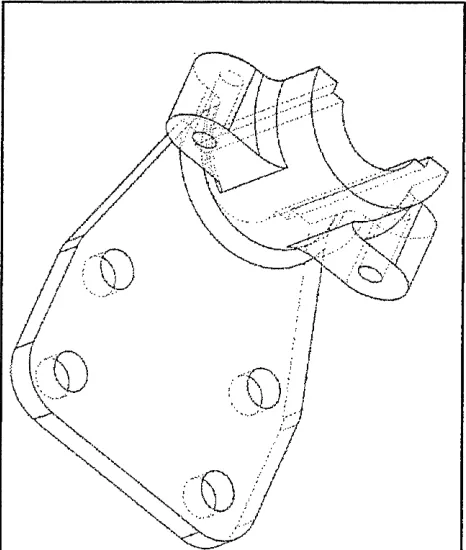
Wireframe modelling provides the ability to model pictorial views using a series of
points in space joined by lines to represent the edges of the object as shown in Figure 1.1
below. Its advantage is that it can provide pictorial views of components which are not
easy to interpret from 2D drawings, however as the model consists of lines, it can be
confusing. The surface area or volume of the model is indeterminate and it is not possible
to produce mass properties or machining information from the model. Because of this
Figure 1.1 Wireframe model of a bracket base
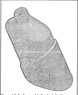
Surface Modelling, shown in Figure 1.2, allows the presentation of the component
in the form of a mesh, the fineness of which can be specified by the user. It is more
generally employed for defining complex doubly curved 3D surface geometries for styling
such as car bodies, aircraft structures etc. The surface model consists of points in space
linked by "Patches" which form a surface skin of zero thickness. Surface mesh information
can be used to provide machining information to produce a component or production
tooling or passed to "Finite Element Analysis" (FEA) packages for stress and heat flow
I . ' ' ’
Figure 1.2 Surface model of a plastic bottle
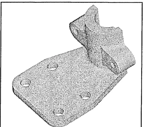
Solid Modelling, illustrated in Figure 1.3, in which models are built up from 3D shapes,
provides greater visualisation of a component, especially where the use of colour
shading and highlighting is used. A solid modeller defines both the outer skin of the
component and the material or spaces contained within it. It is possible to generate areas,
volumes, weights, centres of gravity and moments of inertia from the model. The same is
true of surfaces, but solid modelling computers are faster because "standard shapes" are
[image:31.614.139.414.38.373.2]p§§
I lif*S
Figure 1.3 Solid model of a bracket base
However, although 3D may be regarded as the ultimate system in terms of potential
benefits, there are drawbacks. A solid model is far more complex than a wire frame or
surface model and the definition of a complex 3D object requires a large memory store,
especially where companies are networking 3D modelling applications(19). The
construction of models can be time consuming and difficult and great emphasis must be
placed on accuracy of models where CNC/ CAM is to be employed than with models
intended for drawing output or FE analysis. Generally it is not possible to machine a solid
model directly, however many modern packages allow the user to convert to a surface
type model before machining.
The time taken for designers to become fully conversant with such packages can be as
much as a year and it is almost impossible to use, know or remember every aspect of a
[image:32.614.162.396.46.253.2]1.3.3 CAD- Fields of Application
CAD is used in every branch of engineering, too numerous to list completely, but as an
example it is employed in:
► Mechanical Engineering
► Aerospace Engineering
► Petrochemical Industry
► Medical
► Agriculture
► Architecture
► Electrical and Electronics Industry
► Automotive Industry
► Food Processing Industry
Within these categories there are individual CAD packages written specifically for that
industry and other packages that transcend the industry or product area to provide a
package which can be used generally by any discipline. An important point to note is that
over the last 10 years there has been a multitude of different CAD systems on the market
from low cost to very expensive.
Compatibility between systems and the integrity of data can be a problem in transferring
drawings from one system to another, in spite of the standard data exchange formats of
IGES, STEP and DXF (20-22). This may generate problems for companies transferring
data to, or from, customers and can negate the benefits to be gained from electronic
format. Many companies employ more than one CAD system, often because companies
have a number of separate departments, are subsidiaries or are part of a larger group and
CAD is not just a function of the design department but is an integrating technology (23),
having the capability to integrate activities and information across the company using
geometric models for marketing, design and manufacture functions to provide a strategic
impact on company performance.
Hence the aims of this research, to ascertain and identify the contribution and relevance
of human factor issues within a successful CAD implementation methodology and to
develop a human factor understanding for aiding effective CAD introduction is an
important contribution to the engineering design field.
1.4 THESIS STRUCTURE
This thesis consists of eleven chapters and five appendices
Chapter 1
Reviews the aims of the research and the historical development of computers leading to
the current day use of 2D and the more complex application and use of 3D CAD.
Chapter 2
Reviews the literature in the areas of Human Factors and relates the topic to the
implementation of new technology and in particular CAD. It identifies three critical factors
which influence CAD implementation, Strategic planning, Organisational change and
Training and proposes their use as the initial basis of the research from thereon in.
Chapter 3
Describes and justifies the research methodology chosen for the initial pilot study and
presents the results, identifying the focus for further research via case studies.
The chapter proceeds to describe and justify the methodology used for case study research
and the framework employed for selecting companies for inclusion as case studies.
Chapter 4
research development via further case study work.
Chapter 5
Presents the results obtained from further case study work.
Chapter 6
Discusses the results of case study work and presents a Model for effective CAD
implementation together with propositions for further validation of the model via a
national survey of UK companies.
Chapter 7
Describes the research methodology chosen for the national questionnaire survey and
presents justification for its use.
Chapter 8
Presents the results of the national questionnaire survey.
Chapter 9
Discusses the results of the national survey. It identifies problems which companies are
experiencing, indicates the limited internal support provided by these companies and the
poor ratings which staff give this support.
Chapter 10
Reviews the three stages of the investigation, Pilot Study, Case Study and National
Survey and draws together conclusions from each stage to show the significant influence
of the research issues on CAD implementation.
Chapter 11
2.0 LITERATURE REVIEW
2.1 INTRODUCTION
This chapter reviews the literature in the areas of CAD and human factors in order to
provide:
1) An understanding of:
• The issues involved in a successful CAD introduction and development.
• The meaning of human factors and their application to CAD.
• The role which CAD can play in the current and future operational and business
success of UK companies.
• CAD implementation strategies and models for success.
2) Identification of the critical factors which influence CAD implementation as a basis for
the research from hereon.
A1 Requirements for Successful CAD Implementation
The results of a keyword search of the INSPEC Computer & Control Abstracts database,
shown in Figure 2.1, clearly indicate that most research previously undertaken has been
concentrated primarily on the technical aspects of CAD followed by organisational aspects,
•£1500
IT and H um an fa cto rs
0 i i ' "I' i i 1 ~ l" i i i" i I r i i r r~'"i i r i !
80 81 82 83 84 85 86 87 88 89 90 91 92 93 94 95 96 97 98 99/00/01
Y ear
Figure 2.1a Results of search on the INSPEC computer database
300
250
j2 0 0
*150
•0100
E
50
j ( CAD and E ducation CAD and Training [~ | CAD and S kill
| CAD a n d H u m a n F a c t o r s
1
~r i i i ''] —t—i—i—i—i—i—i—i i i i r r
80 81 82 83 84 85 86 87 88 89 90 9192/394 95 96 97 98 99 /00/01 Year
CAD and Benefits
1600
1400
®1200 « 5 M000CO
©
a ^ 800
o
e
® 600
X I
E 3
2 400
200
0 CAD and Software O CAD and Applications [ j CAD and Hardware
80 81 82 83 84 85 86 87 88 89 90 9192/394 95 96 97 98 99/00/01
Year
Figure 2.1c Results of search on the INSPEC computer database
[ ] CAD and Design ] CAD and Implementation ] CAD and Organisation
B4000
£3000
•O2000
1 1---1---1 I I I 1 r T 80 81 82 83 84 85 86 87 88 89 90 9192/394 95 96 97 98 99 /00/01
Year
However a more detailed review of the literature on CAD implementation suggests that to
achieve both greater success and staff job satisfaction, companies should consider
Technical, Organisational related (ie structural) and Human issues.
For instance, in 1988, in a report by Coopers and Lybrand (24) Stark reported that although
CAD had been in use for the last 25 years, many companies were not able to report
significant effects on the business. He states the reason for this is that companies do not
address both organisational and human issues. Stark acknowledges that no one single form
of organisational structure will be relevant to all companies or industrial sectors. Instead he
suggests that what is required is an organisational structure which allows the CADCAM
system to be used as effectively as possible.
Part of this structure will be the introduction of CADCAM procedures and he highlights
three main ones as:
• Design office procedures- How design is carried out at the company.
• User interface- Procedures for creating symbols, 3D models.
• System procedures- by system support staff; eg printing, plotting, back-ups,
archives, enhancements, security.
With reference to people, he advocates wider job classification and responsibilities, coupled
with better training and job advancement linked to skills and results.
In the same year, Strachan, Cross and Black (25 ) reported on barriers encountered during
the implementation of CADCAM at one Scottish company, classifying the critical barriers
to effective implementation as "Organisational" and "Technical". They quote several
• Middle management approaches/ CADCAM management
• Control of information.
• Responsibility and accountability.
• Training/ learning curves.
• Project/ workstation utilisation.
Strachan, Cross and Black suggest that technical barriers to effective implementation
included:
• No CADCAM system expansion.
• The user interface.
• Applications ability of the system.
• Database size and re-use of data.
Their description of these "technical barriers" however show that many of the technical
problems observed are really a result of management and organisational planning and
decisions taken during the implementation process.
One year later in August 1989, Majchrzak and Salzman (26) also reported that research had
shown that 75% of firms had not achieved their intended benefits of CAD. They too suggest
that the reason for this was in-adequate planning by managers concerning organisational/
structured new technology change. Majchrzak and Salzman's viewpoint is to suggest that
managers feel that the introduction of advanced manufacturing technology (AMT) does not
require organisational and structural change and that any such changes would occur as a
result of the technology; an unwise "Before the event" approach to CAD implementation.
However, they cite research examples to suggest that when organisational change is
anticipated benefits.
In 1988 Beaty and Gordon (27) in looking at a range of North American companies and
surveying 200 managers and operatives, identified their own independent three barriers to
successful CAD introduction:
• Structural- ie organisational structures and systems.
• Human- Employee perception, skills and biases.
• Technical-ie As a result of the incompatibility of CAD systems and the ability to
transfer data between different systems.- However, they consider such technical
problems the easiest to overcome.
Interestingly though, they cite that North American managers preferred action ie a short
term, reactive/ firefighting approach to managing rather than careful long term planning.
They traced these attitudes to the many implementation mistakes which they suggest they
observed during the course of their research related to hasty decisions based upon impulse
rather than any structured analysis of the technology. Beaty and Gordon therefore suggest
that long term planning is desirable.
However, in conclusion they cite cases where companies did not undertake advance
planning but still had successful results- provided that they:
• Did not make serious people mistakes.
• Had a facilitating organisational structure.
During 1989 Mortensen and Nehring (28) outlined some of the critical factors involved in
increased CADCAM/CAE productivity in the USA through a study in which participants
support and training during and after the introduction of CAD. From their survey of 216
users, managers, vendors and consultants in a range of small and large companies, effective
internal support organisation for the system is cited as the most important aspect required
for achieving CAD effectiveness.
In conclusion they propose six critical factors for CAD effectiveness shown below.
► Formal procedures for review and evaluation of CAD issues and problems.
► Regular user/ management meetings.
► Use of the system for 3D as well as 2D.
► Use of an implementation plan.
► Continued formal involvement and support from vendors.
► The establishment of in-house support organisational system.
A more European perspective, within the field of electrical engineering was provided in
1993 by Kratzer and Kratzer (29). They emphasise the embracing nature of CAD on other
departments in a company as well as the design department and propose that CAD
introduction should be a project under the control of a committee made up of expert
members from each department.
They further emphasise however that implementation is foremost an organisational activity
and a technical activity second. They further suggest that CAD implementation without
effective planning, preparation and structured training provides little improvement over
conventional manual methods. Where an effective implementation methodology is
employed, the benefits include productivity, quality, user and customer satisfaction. They
particularly indicate that the "Human factor" role (ie employee motivation, job satisfaction
Even though the previous research cited above had resulted in significant recommendations
for effective implementation, reports of problems with the implementation of CAD were
still appearing in 1994 and the reasons for such failures were suggested by EDS
Unigraphics at their 94' roadshow (30).
ie.
• Lack of clear business objectives.
• Lack of top down commitment.
• Lack of commitment on a day to day basis.
• Failure to address human and organisational issues.
• Training rather than educating users
B) Definitions of Success
Success may mean different things to different companies and individuals. In an earlier
study by Short (31) 94% of companies believed their CAD implementation to be successful.
Unfortunately 69% of the companies failed to achieve the benefits that they initially
anticipated. Equally important is that most of the benefits were purely productivity related
rather than technology exploitation related.
Black (32) and Kidd (33) suggest that to compete successfully in the future, success ought
to be based upon competitive factors such as, quality, flexibility and cost effectiveness
rather than just productivity increases. These early proposals were still being re-emphasised
in 1999 by Kunwoo Lee (22) as vital for companies to survive worldwide competition.
Unfortunately, to date, the UK marketing of new technology has been instrumental in
by companies in preference to exploiting the potential of technology for human reasons.
Bjom-Anderson (34) highlights the above in a research paper concerned with human factors
and the introduction of computer systems and suggests that "At the moment all we are
doing is to adapt the technology to the known human weaknesses in order to reduce the
resistance to the technology, rather than providing a technology which will help to liberate
the intellectual capabilities of human beings
2.2 HUMAN FACTORS
A) Definitions of Human Factors
Perception of the meaning of the term "Human Factors" has been found to vary dependent
upon the views and working objectives of the user. McCormick (35) suggests human
factors research is concerned with enhancing human activity, skill and welfare and its'
application to achieve greater effectiveness of system use by personnel, whether that system
be mechanical, electrical or computer based etc. However, he also suggests the term may
be known as biomechanics, engineering psychology or ergonomics.
Meister (36) attempts to give a more complete range of meanings of the term from:
a) The physical interaction of personnel, equipment, environment and job roles.
b) Skill requirements of personnel.
c) The effects of systems on personnel and vice-versa- ie effects on use, motivation
and attitudes.
d) The term used to define the field of work undertaken by human factor specialists.
\j x w n i ^ u t v > i m i v i u v u v n t v / i / v p w v v u ^ x x v x v /x u i v i i v u u i n ^ v x j ^ i g v i i v i i u v i j v v i m u i .
"Human Factors" would be involved with the cognitive aspects of computer interaction.
A definition obtained from the world wide web (38) indicates that in North America,
ergonomics is known also as human factors and is used to interpret the science that relates
to the design of products, systems and environments for human use. However, it appears
to be more physically based with emphasis on the physical interaction of people and
products.
Stanton (39) supports Beard and Peterson's view of Human factors but uses the words
"Human Factors" and "Ergonomics" interchangeably. He concludes that the overall
objectives of human factors are to " Optimise the Effectiveness and Efficiency with which
human activities are done". He also emphasises its objective in improving the quality of life
and makes specific reference to such things as stress, comfort and satisfaction.
This latter definition is the one which is used as the main thrust within this research work
because it fits more closely with the organisational and structural introduction of CAD,
rather than its physical introduction and use, although due recognition is given to the
contribution of ergonomic factors to effective system use.
B. Approaches of Human Factor Application to Computer Systems
Clegg (40) points to the fact that even with the large endeavour that has taken place in
human factors understanding, there remain very few models or methodologies which can
be used practically to aid with the human/ organisational definition or application of what
he terms appropriate systems requirements.
Clegg points out that this may be linked to the great variances in company organisations,
cultures and subsequent requirements for new technology; which subsequently leads to
requirements for different implementation strategies.
However he does accept that there can be some general trends which could be common to
Such commonalities and general trends between companies could be used to form the base
point for providing tools and methodologies which could then be incorporated into an
implementation plan for achieving maximum effectiveness; technical, organisational and
social. To achieve this means that companies’ would require a corporate identity of human
factors which could be included into a corporate strategy.
The foregoing perspective falls somewhere between conventional approaches to human
factors and that proposed by Kidd (41). He recognises the need to discard technology led
approaches in favour of one which considers technology, organisation and people, but
suggests that traditional human factor approaches also need discarding since their objectives
have been concerned more with the technology than with appropriateness to company and
employee. He emphasises the need to change thinking based upon organisational concepts
developed in the 19th century and beliefs that employees in manufacturing were not
required to use any skill, creativity, judgement or experience in their jobs.
Further evidence of such views abounds in the literature on I.T. Cross and Bawden (42)
emphasise what other researchers have said and suggest that effective use of technology will
only be achieved if sufficient consideration is given to human and organisational issues.
They also emphasise the effect that I.T would have on the "blurring of job boundaries"
McCluney (43) also addresses the problem of employees. He observes that most businesses
(especially IT) provide long term strategies for the maintenance and development of
machines and equipment but often fail to provide similar long term strategies for the
development of personnel.
More recently, authors are still indicating that the competitiveness of industry should be
Kochan(44).
Bullinger (45) points to human problems encountered by users of standard computer
packages when applied to non-standard problems. He suggests that any computer
application programme provides standardisation of problem conceptualisation and that
should a problem fall outside the standard capabilities of computer packages it is the
competence, experience and qualifications of the user that will influence the problem
solution.
An example of one type of problem that may fall outside the constraints of software
packages are given by Wolfe (46). He emphasises the irrational behaviour of CAD systems
due to very small defects in CAD model representations which can result from:
• Operator error.
• Programming errors in the CAD software.
• Illegal geometry.
He suggests that in order to achieve effective CAD, both CAD users and their managers
must be aware of the type of defects in CAD models, when and how they occur and how
such problems are rectified. Clearly more fundamental understanding is required from a
CAD user than just operating a system to reproduce a drawing or geometric model.
Bullinger states that to cope with non standard situations, users must have a commitment
to continual training, particularly towards a self centred training approach.
This suggests that for companies to achieve objectives of technical, organisational and
business success requires a rethink on organisational and policy approaches in order to
engender this culture into the company across the board.
On a practical level this culture change therefore needs to embody the concept of structured
workforce, ie broad based training within a range of subject areas; structured training for
tomorrow not today.
Unfortunately the incentives to persuade a workforce to accept the need for such training
are not always there. In particular, Liker & Fleischer (47) undertook a survey of two large
companies involving seventy four CAD users and thirty non-CAD users. One of their results
was that whilst the general perception is that managers would choose the better educated
and qualified personnel to use CAD, for some reason education reduced the chances of
being selected to use CAD. Further to this they suggested that a ten year age difference
between designers produced a 20 percent lower probability of being selected to use CAD.
To some extent, certainly in the early days of CAD but less true today, age discrimination
may be related to younger staff being more computer literate and keen to further their
careers than older staff.
Mandeville (48) in a quantitative survey to discover the impact of a CAD system on the
design and draughting personnel within an American product design engineering company
relates their job characteristics' perceptions in terms of skill variety, autonomy,
responsibility, team working, work based learning and their degree of involvement in the
work etc. to the routineness of the job.
He finds that the role of draughter & designer correlates closely with individuals
perceptions of routine and non-routine work. An idea which is probably backed up by the
traditional view of the designer as an innovator and creator of ideas with a wide knowledge
of engineering topics, able to apply critical thought to new and challenging problems,
into working drawings.
According to Mandeville those involved in doing routine work appear to have reached a
lower educational level than the non routine group. It is within the low experience group
of routine workers that he sees his main conclusion; ie this group tends to perceive more
negative aspects from the introduction of CAD than more experienced users.
Obviously the very subtle differences between employee perceptions are difficult to analyse
or pre-determine since they will depend upon background and experience.
For example, some people would perceive a half cup of water as being half full and some
as half empty; perhaps the perception being a function of accustomedness to having or not
having and the need to have.
Consequently the above set of factors, although not leading to an understanding of
individual perceptions, does indicate that their perceptions may be modified by experience
and training.
This suggests that prior to and during implementing a change from manual design to CAD,
a company will need to consider aspects such as:
a) Preparing the workforce early on to accept this and any other future technological
change through continual training, education and support.
b) Ensuring a need that the technology is relevant to the company and the workforce.
2.3 THE NEED FOR CAD
There appears to be fairly widespread agreement amongst experts and practitioners
regarding the general benefits and limitations of CAD (49-50) such as increased
productivity, quality, visualisation etc. and these were indicated in chapter 1, therefore they
However as Black(32) points out the realisation of these benefits is related to the corporate
strategy formulated by the company towards product design and its' effect on business
success. He suggests that such a strategy is strongly influenced by the market place and
should be directed towards achieving the development of "New" products able to compete
with other companies products.
In his paper on human factors in computer aided manufacture Kidd (33) quotes Bolwyn et
al-1986 and gives evidence to support the above idea indicating how non-price factors have
become significantly more important than price factors since the 1960's. Kidd suggests that
flexibility had become a competitive factor requiring companies to be able to continually
update and customise products. He further predicts the way forward for achieving a
competitive edge in the 1990's and beyond as involving quality, flexibility & cost efficiency.
To do this successfully he suggests that companies need to become "learning organisations"
in order to continually improve operational and business activities.
These factors are now more prominent because of the requirements of the market for large
product variety, short product lives and lower production costs.
CAD (both as a stand alone or integrating technology) has the capability to help companies
achieve the competitive factors outlined above and examples from the literature are
discussed below.
Macphee (51) illustrates the influence that CAE can have on the quality of design and
subsequently on the overall product cost during the design and construction of process
plant. His paper considers the design of process plant using an integrated CAE system, ie
a series of databases linked together with a 3D modelling system. He identifies five areas
• Design Quality.
• Design Effort.
• Programme savings.
• Materials.
• Design visibility.
Macphee quantifies the overall cost savings as being in the region of 4% to 5% for typical
process plants, which on a multi-million pound project is a significant sum.
Mills (52) parallels Macphee's proposal within the field of automotive engineering and
quotes examples from Ford and Rolls Royce to show that 70% to 80% of the
manufacturing costs of a product is influenced at the design stage.
Consequently the opportunities provided by the efficient and effective use of CAD
techniques is vital to a companies' business success.
Mills also suggests that designers can be helped to improve their designs and consequently
final costs, by employing tools such as Design for Manufacture (DFM), design for assembly
(DFA), failure modes and effects analysis (FMEA), value analysis, and material selection
etc. which are integrated into the CAD/CAM system.
Ebel & Ulrich 1987(53) undertook a comparative study of CAD from eight different
countries; France, Germany, UK, Hungary, Sweden, USA, Japan and the USSR. At that
time they hypothesised that the use of CAD provides new or additional fields of technical
work such as 3D, macros, kinematics & simulation etc.
Any new fields of work will require staff to be both trained and supported to execute their
job roles efficiently. Thus part of the research strategy adopted within this thesis will be to
length of time that CAD has been employed at the company and the length of time CAD
technology has been available.
From his experience as a consultant and involvement with a number of CADCAM
implementation projects, Looney (54) emphasises the human aspects of CAD usage and
suggests that the technology provides opportunities to improve personal characteristics of
the employee in terms of personal effectiveness, motivation and development etc. However
he warns that because managers believed the introduction of CAD would generate
resistance to the change, they limited training to "basic" or "awareness" training and as a
result were not therefore achieving the maximum potential from their systems.
One company's view, based upon experience (55) encompasses both of the above themes.
Davy (Sheffield) were forced to implement new technology because of competitive needs
but believed that the changes would also have an important effect on human issues such as
the attractiveness of the job and upon other peoples image of engineering.
2.4 IMPLEMENTATION STRATEGIES
Several authors suggest that CAD is an integrating technology. Majchrzak et al(56) stated
that CAD should not be introduced in isolation but should be integrated with the other
sections and departments within the company so that there is joint use of information.
O'Reilly (57) discusses the integration of CAD and CAM into an electronic CAE system for
PCB and hybrid microcircuits. He too identifies the benefits but explains that the systems
available were not completely integrated and users were not sufficiently CADCAM aware
to be able to plan the implementation of a new technology and at the same time plan the
Miles (58) supports the views of Majchrzak and re-iterates the comments made earlier in
the literature survey about changing market requirements in terms of quality, cost and lead
time and discusses the role of Simultaneous Engineering in addressing those issues. In
particular he emphasises the benefits of integration of information, such as:
• A common database and data input.
• The ability to re-use/ extract information and data.
• The ability to trace the history of decisions.
He illustrates how integration of data is employed between concurrent engineering design
tools such as DFM, DFA, FMEA, QFD etc and explains that the use of such tools is a
critical requirement for effective product introduction.
Such design tools, originally developed as design philosophies and techniques, can be
employed both manually or as computer tools.
Therefore in undertaking the case studies and national survey within this thesis, evidence
of the use of such manual tools or their integration will provide a view as to whether a
company is doing more than just using CAD as an electronic drawing board.
Bessant et al (59) however make the point that the full potential of the technology is often
restricted because companies fail to achieve simultaneous organisational and technical
change.
However they also argue that it is impossible to plan organisational change simultaneously
with technological change; their solution being concerned with finding the best fit between
choices and contingencies.
which will presumably aid obtaining this best fit, even though companies have different
organisational structures, markets, products and abilities etc.
They suggest that the pivotal trend should be focused on providing an organisational
structure which embodies the concept of flexibility and decentralisation. Such comments
are also supported by Stark (61). He suggests that there is no one CADCAM organisational
form but that traditional hierarchical forms of organisation are not appropriate for a
CADCAM environment. Instead he recommends flatter organisational structures together
with broader job responsibilities and free flow of information between functional areas of
the company.
In a latter paper in 1988 Tranfield & Smith (62) also note the importance of a culture (such
as the Japanese) which sees planning as being a shared responsibility and experience
between all levels of the workforce. They also identify the "pace” of change in terms of a
"sprint" followed by a period of calm, as being a key element of any strategy which will lead
to the successful implementation of technology.
The "pace" of change suggested is really a common sense logical idea tha