Abstract— Modeling and control of a 50KW Electric Vehicle battery fast charger Power Factor Correction stage, developed at Gamatronic Electronic Industries LTD, is presented in the paper. The charger topology may be referred as a two-stage controlled rectifier. The input stage consists of a three phase full bridge rectifier combined with an active power filter (three single stage power filters are actually employed). The input stage creates an uncontrolled DC bus while complying with the grid codes by keeping the THD and power factor within the permissible limits. The output stage is formed by twelve DC-DC converters and is perceived as a constant power load by the input stage. The active power filter is operated using all-analog control circuitry according to the predetermined grid interfacing behavior. Input stage hardware and control loops are explained throughout the paper and extended simulation/experimental results are presented.
Index Terms—Electric vehicle, Power Factor Correction,
Active Power Filter, Analog Control.
I. INTRODUCTION
HE traction battery (typically of the lithium-ion type) is undoubtedly the most critical component of an electric vehicle (EV), since the cost, the weight as well as the reliability and driving range of the vehicle are strongly influenced by the battery characteristics [1], [2]. Moreover, the battery must be properly managed, and in particular properly recharged in order to utilize its full capacity and preserve its nominal lifetime [3] – [6].
There are two types of battery chargers: the on-board (sometimes called slow or low power) charger, through which the battery is recharged when parking and plugged into a charging spot [7] – [14], and the off-board (so-called fast or high power) charger, located at the Battery Switch Station (BSS) [15], [16]. The slow charger usually operates at 0.1-0.2C rates, while the fast charger rate typically reaches 1-2C rates, i.e. while charging a 25KWh battery; the slow charger supplies 3-4KW while the fast charger peak power is around 30-50KW. The typical concept of EV includes urban driving only, where the full battery charge is sufficient for short-range routes. Recharging is accomplished by plugging the car into charge spots placed at different city locations throughout the day and at driver’s home during the night. Recently, a paradigm shift towards closing the gap between EV and conventional vehicles has occurred, forcing the infrastructure to support EV intercity
A. Kuperman is with the Hybrid EnergySources R&D Laboratory, Ariel University Cented, Ariel, 40700 Israel; e-mail: [email protected].
U. Levy, J. Goren, A. Zafransky and A. Savernin are with Gamatronic Electronic Industries, LTD., Jerusalem, Israel.
driving as well. The following concept of BSS was developed: when out of charge, the EV battery can be replaced at a BSS, allowing nearly uninterrupted long range driving. The near-empty battery, removed from a vehicle at the BSS, is charged by a fast charger (FC), and is available as quickly as possible for the next customer.
The FC is basically a controlled AC/DC power supply, drawing the power from the three phase AC utility grid and injecting it into the traction battery. In order to provide a feasible solution, the FC must satisfy both the grid code in terms of THD and power factor from the utility side and lithium-ion charging modes from the battery side.
Since the BSS usually contains multiple FCs, its impact on the distribution grid is very significant, as was shown by previous research [17]-[23]. Therefore, the input stage of the FC usually performs rectification and Power Factor Correction (PFC) according to the regulation requirements. It can be accomplished either by employing an active rectifier [24]-[26], or a diode rectifier combined with a PFC circuit. The well-known single phase PFC approach, where a full-rating boost DC-DC converter follows the diode rectifier [27] is unsuitable for the three-phase case. However, it can either be modified by splitting the three-phase rectifier into two single-three-phase legs followed by two independent PFC converters [28]. Alternatively, a more elegant approach employs a shunt connected Active Power Filter (APF) at the rectifier input, supplying the reactive current to the diode rectifier and thus achieving both near unity power factor and near zero Total Harmonic Distortion (THD) by forcing the utility to supply the active current, which is in phase with the utility voltage and of the same shape [29]–[35]. The use of either one three phase [29] – [32] or three single phase [33]-[35] APF configurations are potentially feasible for implementing a three phase PFC. The additional advantage of the approach is the fact that because of the shunt connection, the APF rating is approximately 40% of the series-connected PFC circuit rating, since the APF supplies the reactive power only to the diode rectifier (which is around 40% of the active power, flowing through the rectifier), while the series connected PFC converter supplies the active power, demanded by the load.
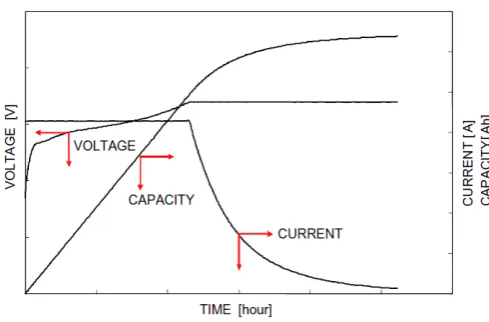
A lithium-ion battery charging is characterized by two main phases: constant current (CC) and constant voltage (CV), as shown in Fig. 1. The battery is charged by a constant current until the voltage reaches a predetermined level. From this point the voltage is kept constant while the current reduces as the capacity approaches 100%. Hence, the charger output stage must be capable of operating either as a current source or as a voltage source and is
Modeling and Control of the PFC Stage for a
50KW EV Fast Battery Charger
A. Kuperman, U. Levy, J. Goren, A. Zafranski and A. Savernin
implemented via an interleaved DC-DC conversion stage, perceived as a constant power load by the PFC stage.
Fig. 1: Lithium-ion battery charging modes
The paper describes modeling and control of the PFC stage for a 50KW FC, employing a three phase diode rectifier combined with three single phase APFs as the input stage. The charger operates as a voltage supply with controllable dynamic current limitation. The charger operates from the 380V three phase utility grid and is able to charge lithium-ion batteries within the power range of 0 – 50KW by supplying DC current up to 125A.
[image:2.595.47.294.439.549.2]The rest of the paper is organized as follows. Section II presents the FC overview while the PFC stage operation is presented in Section III. Extended simulation and experimental results are shown in Section IV and the paper is concluded in Section V.
Fig. 2: Fast Charger block diagram
II. FAST CHARGER OVERVIEW
The block diagram of the 50KW FC is shown in Fig. 2 [36]. The charger is connected to a three phase four wire 380V AC distribution grid. The input stage comprises a three-phase diode rectifier, enforced by three single phase APF as a PFC circuit. Each APF is connected between a power phase and the neutral line. The current, drawn by the rectifier (iDR for the R phase) is created by summation of the
grid (iR for the R phase) and APF (iFR for the R phase)
currents. The THD of the current, drawn by a three-phase diode rectifier with a resistive load (which is approximately the case in the FC) is around 31%. Therefore, taking into consideration a unity displacement factor, the power factor is way below the 92%, required by the regulation. Hence the APF should supply as much as possible of the rectifier current harmonic content, leaving the utility to supply
mainly the first harmonic. The active power filters employ an independent control board, executing a control related to the grid requirements only, independent on the charging mode and power.
The rectified voltage vIN is supplied directly to the output
stage (note that there is no DC capacitor inserted between the stages). The output stage comprises twelve 4.5KW buck DC-DC converters, connected in parallel. The DC-DC converters are operated in an interleaving mode, divided into six groups of two converters, allowing significant reduction of both input and output currents of the DC-DC stage iIN and iO, respectively. A single output capacitor is
connected at the charger output to further smooth the output current and allow output voltage adjustment prior to battery charging.
The EV battery charging is performed in a master-slave manner. The battery operates as a master by sending a power request to the charger via CAN bus. The charger operates as a current source and calculates the desired current by dividing the battery power request by the measured battery voltage. Hence, the DC-DC stage is perceived as a constant power load by the PFC stage.
III. PFCSTAGE MODELING AND CONTROL
Single phase APF hardware, employed in the input stage of the FC, is shown in Fig. 3. The APF is implemented as a four quadrant DC-AC buck converter, connected to the utility via an inductor. Since the APF supplies reactive power only, single capacitor at the DC side is sufficient. However, since there are some power losses in the APF, the power balance of the capacitor must be ensured by a respective control loop in order to compensate the losses in the APF by drawing a small amount of active power from the utility. The outer PI control loop operates to maintain the power balance by keeping a constant DC link voltage at a level above the line voltage, as shown in Fig. 4, where VREF
and VC are the desired and measured DC link voltages,
respectively.
The inner loop implements an indirect current control, i.e. instead of the filter current the utility current is sensed and controlled.
[image:2.595.311.533.582.767.2]Fig. 4: Active power filter: control hardware
Recall that in order to operate with a near unity power factor, the utility current should be in phase with the utility voltage and have the same shape, while its magnitude should be equal to the first harmonic magnitude. The power balancing loop calculates the utility current magnitude A
while the sinusoidal shape is achieved by sensing the utility voltage and forcing the current loop reference current to follow it.
The utility voltages are given by
(1)
)
3
2
sin(
)
(
)
3
2
sin(
)
(
)
sin(
)
(
t
V
t
v
t
V
t
v
t
V
t
v
T S R with3
2
380
V
. The corresponding line current templates are calculated as(2)
n
R
S
T
V
t
v
t
i
nTn
,
,
,
)
(
)
(
in order to achieve a near unity power factor operation. Hence, utility current references are given by
. (3)
i
Ln*(
t
)
A
i
Tn,
n
R
,
S
,
T
The inner PI loop processes the difference between the utility current reference and the measured line current (iL inFig. 4) and calculates the desired APF voltage signal. The signal is fed into a bipolar PWM circuitry, which outputs gate commands to the APF transistors according to the desired current sign.
IV. RESULTS AND DISCUSSION
In order to validate the proposed design, the system was first modeled and simulated using PSIM software. The output stage was modeled as a pulsed 25KW → 50KW →
25KW time varying constant power load. The harmonic currents drawn by the diode rectifier are shown in Fig. 5. The highly nonlinear nature of the current dictated by the constant power load is evident.
The input stage performance is shown in Fig. 6. Despite the highly nonlinear currents iD drawn by the diode rectifier,
the utility currents iS are nearly sinusoidal and in phase with
the utility voltages vS, since the APF supplies the majority of
harmonic content iF of the rectifier currents iD.
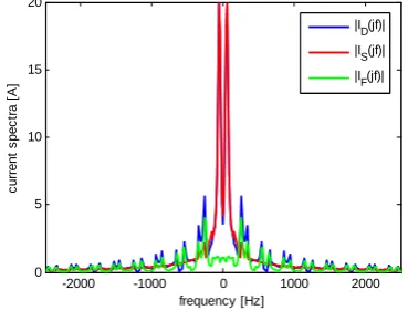
In order to emphasize the filtering function of the APF, the R phase spectra of the utility, rectifier and APF currents are shown in Fig. 7.
0.75 0.8 0.85 0.9 0.95
T ime (s) 0 -50 -100 -150 50 100 150
[image:3.595.314.544.129.266.2]I_nonl_R I_nonl_S I_nonl_T
Fig. 5: Constant power loaded iode rectifier currents
Note the harmonic content of the diode rectifier currents, concentrated at
6
n
1
harmonic, supplied by the APF, leaving the utility current spectra to contain energy mainly at first harmonic.0 -200 -400 200 400
vR vS vT
0 -100 -200 100 200
iR iS iT
0.75 0.8 0.85 0.9 0.95
Time (s) 0 -50 -100 50 100
[image:3.595.312.543.347.513.2]I_comp_R I_comp_S I_comp_T
Fig. 6: Input stage performance: upper – utility voltages, middle – utility currents, lower – APF currents.
-2000 -1000 0 1000 2000 0 5 10 15 20 frequency [Hz] c ur re nt s pe c tr a [A ]
|ID(jf)| |I
S(jf)|
[image:3.595.334.519.558.698.2]|IF(jf)|
Fig. 7: The R phase spectra of the utility, rectifier and APF currents
The DC link voltages of the three APFs are shown in Fig. 8. The voltages are nearly constant in steady state since the power flow is well-balanced by the outer PI controllers.
currents are nearly sinusoidal and show resistive mains behavior, as desired. The nonlinear rectifier current is well compensated by the appropriate APF current.
0.75 0.8 0.85 0.9 0.95
T ime (s) 0
100 200 300 400
[image:4.595.46.288.257.761.2]Vc_R Vc_S Vc_T
Fig. 8: DC link voltages of the active power filters
Fig. 9: Experimental current vs R phase utility voltage: upper – rectifier current, middle – APF current, lower – utility current.
V. CONCLUSION
A PFC stage design for a 50KW Li-Ion traction battery fast charger was presented in the paper. The charger is basically a two-stage current power supply operated by the battery power requests. The input stage includes a diode rectifier with a shunt connected active filter, achieving excellent results in terms of THD and power factor. The output stage is formed by six interleaved groups of two parallel connected buck DC-DC converters, perceived as a constant power load by the PFC stage. Modeling and control of the PFC stage was revealed in the paper. Simulation and experimental results enforce the proposed design by demonstrating similar results
REFERENCES
[1] B. Kennedy, D. Patterson and S. Camilleri, “Use of lithium-ion
batteries in electric vehicles,” J. Pow. Sources, vol. 90, pp. 156 – 162,
2000.
[2] R. Gitzendanner, F. Puglia, C. Martin, D. Carmen, E. Jones and S.
Eaves, “High power and high energy lithium-ion batteries for
underwater vehicles,” J. Pow. Sources, vol. 136, pp. 416 – 418, 2004.
[3] G-C. Hsieh, L-R. Chen and K-S. Huang, “Fuzzy-controlled Li-Ion
battery charge system with active state-of-charge controller,” IEEE
Trans. Ind. Elec., vol. 48(3), pp. 585 – 593, 2001.
[4] M. Chen and G. Rincon-Mora, “Accurate, compact, and
power-efficient Li-Ion battery charger circuit,” IEEE Trans. Circ. Sys. II:
Expr. Briefs, vol. 53(11), pp. 1180 – 1184, 2006.
[5] K. Tsang and W. Chan, “A simple and low-cost charger for
lithium-ion batteries,” J. Pow. Sources, vol. 191, pp. 633 – 635, 2009.
[6] J-J Chen, F-C. Yang, C-C. Lai, Y-S. Hwang and R-G. Lee, “A
high-efficiency multimode Li-Ion battery charger with variable current
source and controlling previous stage supply voltage,” IEEE Trans.
Ind. Elec., vol. 56(7), pp. 2469 – 2478, 2009.
[7] D. Thimmesch, “An SCR inverter with an integral battery charger for
electric vehicles,” IEEE Trans. Ind. Appl., vol. IA-21(4), pp. 1023 –
1029, 1985.
[8] J. Bendien, G. Fregien and J. van Wyk, “High-efficiency on-board
battery charger with transformer isolation, sinusoidal input current
and maximum power factor,” IEE Proc. B, vol. 133(4), pp. 197 – 204,
1986.
[9] S-K. Sul and S-J. Lee, “An integral battery charger for four-wheel
drive electric vehicle,” IEEE Trans. Ind. Appl., vol. IA-21(4), pp.
1023 – 1029, 1995.
[10] B. Masserant and T. Stuart, “A maximum power transfer battery
charger for electric vehicles,” IEEE Trans. Aerosp. Elec. Sys., vol.
33(3), pp. 930 – 938, 1997.
[11] D. Jackson, A. Schultz, S. Leeb, A. Mitwalli, G. Verghese and S.
Shaw, “A multirate digital controller for a 1.5KW electric vehicle
battery charger,” IEEE Trans. Pow. Elec., vol. 12(6), pp. 1000 – 1006,
1997.
[12] L. Solero, “Nonconventional on-board charger for electric vehicle
propulsion batteries,” IEEE Trans. Veh. Tech., vol. 50(1), pp. 144 –
149, 2001.
[13] M. Egan, D. O’Sullivan, J. Hayes, M. Willers and C. Henze,
“Power-factor-corrected single-stage inductive charger for electric vehicle
batteries,” IEEE Trans. Ind. Elec., vol. 54(2), pp. 1217 – 1226, 2007.
[14] G. Pellegrino, E. Armando and P. Guglielmi, “An integral battery
charger with power factor correction for electric scooter,” IEEE
Trans. Pow. Elec., vol. 25(3), pp. 751 – 759, 2010.
[15] N. Kutkut, D. Divan, D. Novotny and R. Marion, “Design
considerations and topology selection for a 120KW IGBT converter
for EV fast charging,” IEEE Trans. Pow. Elec., vol. 13(1), pp. 169 –
178, 1998.
[16] C-H. Lin, C-Y. Hsieh and K-H. Chen, “A Li-Ion battery charger with
smooth control circuit and built-in resistance compensator for
achieving stable and fast charging,” IEEE Trans. Circ. Sys. I: Reg.
Pap., vol. 57(2), pp. 506 – 517, 2010.
[17] J. Orr, A. Emanuel and K. Oberg, “Current harmonics generated by a
cluster of electric vehicle battery chargers,” IEEE Trans. PAS, vol.
PAS-101(3), pp. 691 – 700, 1982.
[18] J. Orr, A. Emanuel and D. Pileggi, “Current harmonics, voltage
distortion and powers associated with battery chargers,” IEEE Trans.
[19] J. Orr, A. Emanuel and D. Pileggi, “Current harmonics, voltage distortion and powers associated with battery chargers distributed on
the residential power system,” IEEE Trans. Ind. Appl.,, vol. IA-20(4),
pp. 727 – 734, 1984.
[20] S. Rahman and G. Shrestha, “An investigation into the impact of
electric vehicle load on the electric utility distribution system,” IEEE
Trans. Pow. Del., vol. 8(2), pp. 591 – 597, 1993.
[21] P. Staats, W. Grady, A. Arapostathis and R. Thallam, “A statistical
method for predicting the net harmonic currents generated by a
concentration of electric vehicle battery chargers,” IEEE Trans. Pow.
Del., vol. 12(3), pp. 1258 – 1266, 1997.
[22] P. Staats, W. Grady, A. Arapostathis and R. Thallam, “A statistical
analysis of the effect of electric vehicle battery charging on
distribution system harmonic voltages,” IEEE Trans. Pow. Del., vol.
13(2), pp. 640 – 646, 1998.
[23] J. Gomez and M. Morcos, “Impact of EV battery chargers on the
power quality of distribution systems,” IEEE Trans. Pow. Del., vol.
18(3), pp. 975 – 981, 2003.
[24] G. Gong, M. Heldwein, U. Drofenik, J. Minibock, K. Mino and J.
Kolar, “Comparative evaluation of three-phase high-power-factor AC-DC converter concepts for application in future more electric
aircraft,” IEEE Trans. Ind. Elec., vol. 52(3), pp. 727 – 737, 2005.
[25] B-R. Lin and T-Y. Yang, “Three-phase AC/DC converter with high
power factor,” IEE Proc. Electr. Power Appl., vol. 152(3), pp. 757 –
764, 2005.
[26] M. Hartmann, S. Round, H. Ertl and J. Kolar, “Digital current
controller for a 1MHz, 10KW three-phase VIENNA rectifier,” IEEE
Trans. Pow. Elec., vol. 24(11), pp. 2496 – 2508, 2009.
[27] K. Raggl, T. Nussbaumer, G. Doerig, J. Biela and J. Kolar,
“Comprehensive design and optimization of a high-power-density
single-phase boost PFC,” IEEE Trans. Ind. Elec., vol. 56(7), pp. 2574
– 2587, 2009.
[28] J. Hahn, P. Enjeti and I. Pitel, “A new three phase power factor
correction (PFC) scheme using two single phase PFC modules,” IEEE
Trans. Ind. Appl., vol. 38(1), pp. 123 – 130, 2002.
[29] H. Akagi , A. Nabae and S. Atoh, “Control strategy of active power
filters using multiple voltage source PWM converters,” IEEE Trans.
Ind. Appl., vol. IA-22(3), pp. 460 – 465, 1986.
[30] J. Nastran, R. Cajhen, M. Seliger and P. Jereb, “Active power filter
for nonlinear AC loads,” IEEE Trans. Pow. Elec., vol. 9(1), pp. 92 –
96, 1994.
[31] D. Pedder, A. Brown, J. Ross and A. Williams, “A parallel-connected
active filter for the reduction of supply current distortion,” IEEE
Trans. Ind. Elec., vol. 47(5), pp. 1108 – 1117, 2000.
[32] S. Kim, M. Todorovic and P. Enjeti, “Three-phase active harmonic
rectifier (AHR) to improve utility input current THD in
telecommunication power distribution system,” IEEE Trans. Ind.
Appl., vol. 39(5), pp. 1414 – 1421, 2003.
[33] H-L. Jou, J-C. Wu and H-Y. Chu, “New single-phase active power
filter,” IEE Proc. Electr. Pow. Appl., vol. 141(3), pp.129 – 134, 1994.
[34] C. Hsu and H. Wu, “A new single-phase active power filter with
reduced energy-storage capacity,” IEE Proc. Electr. Pow. Appl., vol.
143(1), pp. 25 – 30, 1996.
[35] H. Komurcugil and O. Kukrer, “A new control strategy for single
phase shunt active power filters using a Lyapunov function,” IEEE
Trans. Ind. Elec., vol. 53(1), pp. 305 – 312, 2006.
[36] A. Kuperman, U. Levy, J. Goren, A. Zafransky and A. Savernin,
“Modeling and control of a 50KW electric vehicle fast charger,” in