714
©IJRASET: All Rights are Reserved
Modeling and Analysis of a Rocker-Bogie System to
Improve its Performance
Mr. Anup Kumar Jana1, Mr. R Eshwariah2, Mr. M. Ashok3
1, 2, 3
Asst. Professor, Mechanical Engineering Dept, Vignan Institute of Technology and Science, Deshmukhi, Approved by AICTE, Affiliated to JNTUH
Abstract: Rocker bogies are fairly well used by many organizations like NASA, Military and Exploration channels like the National Geographic. Over the past decade NASA has built several roves with the rocker-bogie design due to the fact that it has become a proven mobility application known for its superior vehicle stability and obstacle-climbing capability, the most famous one being the Curiosity rover sent to Mars in 2011, and another one sent to land on an asteroid of interest. But current rocker bogie’s designs are complex, costly and prone to mechanical failures. The current designs employ a six-wheel design which has a few drawbacks addressed in this report. Based on the well-known rocker-bogie suspension system, this report has specifics how the design of the original rover was tweaked and modified to significantly improve its functional and non-functional features in mainly three areas namely the stability, speed, and load-bearing capability. This work was based on findings on total deformation, Equivalent elastic strains and Equivalent stress acting on the proposed design. Extensive work has been done on areas like design, material selection, and operational features. The major one was the addition of an extra set of wheels which helped to maintain continuous contact with the ground. It has helped to increase required frictional force also. Some other non-functional features like a wireless camera addition and Bluetooth control support have also been added for increased functionality. CATIA was used for part modeling and assembly while Ansys was used for meshing and analysis. The maximum increase of up to 41 % was observed in structural stability in the proposed design.
Keywords: Rocker bogie, NASA- National Aeronautics and Space Administration; CATIA; ANSYS; Bluetooth.
I. INTRODUCTION
There is a lot of research going on to explore different planets and the conditions available there in those places. One can get a good idea of a place by seeing some pictures of that place. A rover is a vehicle used for space exploration, designed to move across the surface of a planet or other celestial body. Few rovers have been designed for transportation of members of a human spaceflight crew; others have been partially or fully autonomous robots. Rovers usually arrive on the surface of a planet on
a lander-style spacecraft [1]. There is a need for a rover which is able to operate in different kinds of land terrains as they are used
for tasks which are difficult for humans and are not safe. To do these tasks a rover needs to have a good communication system with the user. In this rover, the rocker-bogie system that was used for Mars mission is taken as a base for improvement and is the
National Aeronautics and Space Administration’s invention [15]. Rocker-bogie is actually a six-wheeled vehicle which has the
unique capability to keep all wheels on the ground at all times. The basic advantage is that the pressure on wheels will be equal. This is very important because the vehicle may tip over if it is not balanced and another advantage is that while climbing over uneven terrain all six wheels will remain in contact with the floor even under load. In most cases, issues like motility, vision and route finding are the same with slight modifications. These fundamental characteristics will make the rover modular and easy to assemble. This will help aid the process of developing different kinds of rovers for different situations or conditions. Currently, many research works are going on which are looking into changes in design and their related technologies. It is also hoped that this work will help to gain knowledge about changing design and technologies and to serve as a base model for further development. Since 1976, NASA has sent many rovers to mars such as Viking 1 and Viking 2 which have been successful in
returning pictures from the surface of Mars in 1997 [2]. Another rover (Pathfinder) was sent to the surface successfully which has
the system which is being discussed [3]. In 2004, Spirit and Opportunity where the two other rovers which employed rocker bogie
systems which were sent to the surface of Mars, but unfortunately, they could not land [4], [5]. The first successful campaign was in
715
©IJRASET: All Rights are Reserved
time. They also developed an autonomous navigation system and gave it various sensor systems so that it can determine the route by itself it made the navigation simpler and easier and eliminated the need to send or receive any signals coming to the rocker system employed it consisted of six wheels and multiple axle systems that allowed the rover to cross obstacles larger that its wheel diameter [6], [7].
There are different ways to control the rover. Some of these are
1) Manual pushing
2) Direct electric supply
3) Radio transmitter
4) Bluetooth transmitter
MIT app inventor was used to avoid the programming part. It does not have requirement of prior programming knowledge or experience and allows us to store data in the cloud for future reference. It uses block building techniques for creating a complex application with excellent design features.
One of the most challenging aspects of rover operation in planetary environments is that mobility must be effective. To complete any type of task for a rover, it should be able to move confidently on any surface. Surface challenges to the rover mobility are fine powders such as lunar soil, larger rocks. The rover must also maintain high wheel traction in rough terrains. If traction is very high, the vehicle will take a lot of power to overcome the force. If traction is very low, the rover will not able to climb the obstacles or inclined surfaces. The rover is said to be stable when it is in a quasi-static state in which it does not tilt over. The simplest approach to reach the static stability is using the geometric model, which is commonly referred to as the stability margin. The lateral stability of the rover ensures that the rover does not tip sideways. As the rover has two symmetric sides, the geometric model is used to find the lateral stability of the vehicle. Lateral stability is computed by finding the minimum allowed angle is
smaller than the maximum angle of incline α on the slope at the wheel-terrain contact points [8].
This work was done to improve the existing design and what can be done to eliminate the shortcoming of the system. One of the major shortcomings of the current suspension system is that it is not stable due to lack of wheel contact with the ground and unstable structure. Currently, it has only six wheels with an interlinked structure and here it is intended to make it more stable by adding another set of wheels and to change the design structure. Another important shortcoming is that the speed of such rovers is very unsatisfactory and here it is intended to change that and make it faster by increasing the wheel contact with the ground and making the structure more stable. When the surface is flat, the speed of the rover will be appreciable and when the terrain is rough, the torque will help the rover climb over the obstacles easily.
II. LITERATUREREVIEW
Hacot H, et. al. [4] described various issues faced by the rover in an alien environment and attempts to solve each of them using
innovative design modifications. The rover features a bio-inspired eight-wheeled drive mechanism, an integrated robotic arm and a stereo vision technique for advanced image processing. The system control, for both the rover as well as the robotic arm, is done using microcontrollers and microprocessors such as Arduino, Intel NUC, and Raspberry Pi. Inspired by nature, a reflex mechanism has also been integrated into the rover design to minimize damage, by automatic safety reflexes. The arm is so
designed to switch between three different end effectors depending upon the task to be performed.Another researcher, [9] focused
on the development and design of the mechanical system on land that took into consideration the features of the water vehicle. The wheels were retracted to enhance the stability of vehicle while it in water mode. Retractable wheels are designed to reduce the loss of the bow wave wheel. It increases vehicle speed maneuvering on the water’s surface. If the wheels deployed, the water flow under the surface of the vehicle will be blocked and distracted by the wheel. The wheel will disturb the water flow path causing a high pressure before the wheel and low pressure after it. This produces a negative pressure that will affect the speed and stability of the vehicle. A low-pressure hole will also reduce the speed of water flow, encouraging the whirlpool flow and increase the loss of
the bow wave. Dongmok Kim et al. [11] has shown an optimal design of a wheel-type mobile robot was designed in order to ensure
716
©IJRASET: All Rights are Reserved
stairs. To evaluate the climbing capability of the optimized rocker-bogie mechanism, the friction requirement metric is chosen, which is defined as a minimum friction coefficient required for a mobile robot to climb a stair without slip. Through a kinetic analysis of a stair-climbing motion, a locomotive strategy suitable for the proposed rocker-bogie mechanism is derived to minimize
slip while climbing a stair and successfully verified through extensive simulations. Another study.[12] described a simple and
computationally efficient rocker-bogie rover model. Under reasonable assumptions, it is possible to determine the rover attitude and configuration, given its position and ground characteristics, and whether the rover will slide, tip over or maintain its balance. The model includes the effect of the manipulator clearly.
The mechanics of the rover has been developed, and the over-actuation of the system leads to the ability to affect the normal forces by applying specific wheel torques. This property has been verified experimentally and can be used for the design of an active
traction control. A graphical interface has been designed to enhance understanding of the system. David P.Miller et al. [13]have
shown thatthe test track motors and gearboxes that are capable of driving the vehicle at speeds in excess of 1m/sec. The wheelie
maneuver has been used at these speeds. When the obstacle is directly under the front wheel, the wheel speeds are turned back to normal, causing the front wheel to ride down the forward side of the obstacle. The initial sensing is currently done with IR
proximity sensors. Some sources[14]have reflected the way how the rocker-bogie system works on different surfaces. As per the
different weight acting on link determines torque applied on it. By assuming accurate stair dimensions, accurately dimensioned
rocker bogie can climb the stair with great stability. The design and manufactured model can climb the angle up to 45˚. Also, they
tested for the Webcam with AV recording mounted on the rocker-bogie system and found satisfactory performance obtains during
this test camera has rotated around 360˚.
During stair climbing test for length, less than 375 mm (15inch) system cannot climb the stair. It can be possible to develop new models of rocker bogie which can climb the stairs having low lengths.
III. EXPERIMENTAL
Firstly, the different parts of the model were selected. The parts used in the rover are the mainframe, motors, links, wheels, copper wires, batteries, Bluetooth signal receiving circuit etc. The most important part of the Rover is a DC motor in order to move the robot. It is needed to be used to power wheels. This is the simplest and most effective steering method. 45 rpm DC motors (360 degrees) with 2.5 KG toque have been chosen to give the rover a nice combination of speed and torque. The body of the rover is as important as any other part of the rover, as it is the one to bear all the load of the rover and to acts the suspension system. The rover needs a chassis to attach all the electronics to. For an all-terrain robot, the use of aluminum is recommended as the material is cheap and easy to work with, while at the same time being flexible and strong. The thickness of the rover is also important as it must be just the right size to work perfectly. But our rover being the one for exploration and recognizance, the material used must be strong as well as flexible all while being resistant to environmental factors all while being resistant to environmental factors like heat, rain, pollution, dust, water, and sand. Due to the mentioned reasons, MS steel was used to build the live model as it satisfies all the required conditions. While the metal is not cheap, it is affordable for the time being. The metal was purchased in sheets and then cut onto required dimensions.
Thermosetting plastic wheels with rubber grips were used so that it can run smoothly in different terrains. A 1.9V radio transmitter battery was used for Arduino (Bluetooth signal transmitter) and 2.12 V lead-acid batteries were used to run the motors which were connected to the wheels. The first operation done was the cutting operation of the metals into required dimensions. Then bending operation was done to bring the components in good working condition. To prevent oxidation and environment degeneration, the anti-rust coating was done and finally, the component was powder coated to minimize atmospheric contact with the metal.
A. Modeling
717
©IJRASET: All Rights are Reserved
B. Analysis
Ansys Workbench 18.2 was used for the analysis of the chassis. After completing modeling in CATIA, the design was imported to Ansys via a Static structural tab in Analysis. All possible forces which could act on the chassis were applied and a report was made. The same process was adopted for both the models and the process was repeated several times to ensure accurate results.
IV. RESULTSANDDISCUSSION
A comparison has been made between a six-wheeled rocker-bogie suspension system and eight-wheeled suspension systems and the results are discussed.
1) Stability: The initial six-wheel design by NASA was widely successful except for the fact that it was unstable under low gravity situations and low friction conditions between the wheel and the ground.
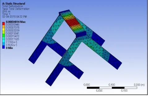
[image:4.612.182.431.235.388.2]A. Total Deformation
[image:4.612.187.426.498.653.2]Figure 1: Total deformation of the 8-wheel rover
Figure 1 and Figure 2 gives the details of the geometry applied in the Ansys software, where the result analysis was done. Another reason for it being unstable is that the load was not equally distributed on all wheels due to the angular placement of the links of the system the first two rows of wheels experienced less load when compared to the third row of the wheels. This problem has been solved in the eight-wheeled rover as the load is distributed equally in all wheels. When we take a look at the above diagram, we can see that there is no deformation at the parts where the wheels are attached. And the load is distributed evenly across the whole surface area.
Figure 2: Total deformation of the 6-wheel rover
718
©IJRASET: All Rights are Reserved
[image:5.612.177.435.102.269.2]B. Analysis Of Structure
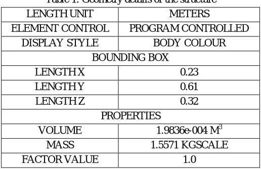
Table 1: Geometry details of the structure
LENGTH UNIT METERS
ELEMENT CONTROL PROGRAM CONTROLLED
DISPLAY STYLE BODY COLOUR
BOUNDING BOX
LENGTH X 0.23
LENGTH Y 0.61
LENGTH Z 0.32
PROPERTIES
VOLUME 1.9836e-004 M3
MASS 1.5571 KGSCALE
FACTOR VALUE 1.0
Before the load is applied, or the fixed points are determined, it is important to mesh the design. Geometry details can be seen in Table 1 and Table 2. Meshing is done to make calculations easier and to pinpoint a stress value at a particular position.
Table.2: Mesh of the structure
Size function Adaptive
Relevance centre Coarse
Element size Default
Transition Fast
Initial size seed Assembly
Span angle centre Coarse
Bounding box diag. 0.726220 m
Minimum edge length 2.e-003 m
Details of the structural steel are given on Table 3 and Table 4.
Table 3: Various constant values of structural steel.
Density 7850 kg m3
Isotropic secant coeff. Of thermal expansion
1.2e-005 c-1
Specific heat constant pressure
434 j kg-1 c-1
Isotropic thermal conductivity
60.5w m-1 c-1
Isotropic resistivity 1.7e-007 ohm m
Table 4: Stresses of Structural steel
Compressive yield strength pa 2.5e+008
Tensile yield strength pa 2.5e+008
719
©IJRASET: All Rights are Reserved
[image:6.612.188.427.295.452.2]1) Load Appliction: The results obtained after the application of load is shown Table 5.
Table 5: Load application on the structure
Definition
Force
Suppresed No
Define by Components
Coordinate system Global system
X component 0.n
Y component 0.n
Z component -50.n
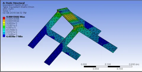
2) Equivalent Elastic Strain: Elastic strain is a form of strain in which the distorted body returns to its original shape and size when the deforming force is removed. This factor is important to consider when we intent to put repeated loads on the rover and send it on missions. Comparison of Equivalent elastic strains can be seen in figure 3 and figure 4.
Figure 3: Equivalent elastic strains of the 8-wheel rover
In a comparison of the values of the elastic deformation, the 6 wheeled rover’s performance is better towards the end side of the wheels, but the overall performance of the 8-wheeled rover beats it. This further establishes the fact the in the performance aspect the 8-wheel design performs better than the 6-wheel design.
Figure 4: Equivalent elastic strains of the 6-wheel rover
[image:6.612.185.425.519.642.2]720
[image:7.612.184.428.79.208.2]©IJRASET: All Rights are Reserved
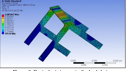
Figure 5: Equivalent stresses in 8-wheel design
Another main reason for the efficient redistribution of the loads is that the design is both horizontally and vertically symmetrical. And that is a very important factor in any design department. Effective stress distribution of the 6-wheeled rover is given in the picture below.
Figure 6: Equivalent stresses in 6-wheel design
In the above images, in Figure 5 and Figure 6, it is clearly observed that the stress distribution is not equal and is more prominent on the front side of the design. This arrangement makes the structure unsteady and unreliable to use in rough terrain unless there are specific changes in the material. The percentage increase has been found by measuring the increase of Equivalent stresses from the 8-wheeled design to the 6-wheeled design, from 2564.4 MPa in the proposed design to 4751.0 MPa in the existing design. Percentage may be calculated simply by finding the difference between the two and divide by the original stress, and then multiplied by 100. Ultimately this analysis proves that the proposed design is better in many aspects than the 6-wheel design and is a good successor to the previous design.
4) Speed: The speed of the rover has been increased considerably from the previous rovers and the fear with the previous design was that the rover would tip over at high speed due to low stability. Now that the fact has been established that the 8-wheeled rover is considerably more stable than its predecessor, the speed can also be increased considerably. The increase in rotational speed of motors was from 30 rpm to 45 rpm and moves towards the motion to create a perfect blend of speed and stability. To get and even better mixture, it is recommended to get 60 rpm motors as is has been noted that the frame has been a little heavy for the 45 rpm motors. The speed can be increased up to 80 rpm if the user prefers to use it in flat terrain but if the user goes beyond 80 rpm then the rover will go out of control and will be difficult to turn it or to control it satisfactorily. The increase in speed has been observed to be around 50% from the fact that the existing design used 30 rpm motors due to stability issues, and since the issues have been addressed to in this version, 60rpm motors can be used. The need to improve speed arises from the fact that sometimes the terrain is flat and the rover must be able to cover the whole distance as soon as possible. So here it makes sense to improve the speed factor.
[image:7.612.186.429.282.418.2]721
©IJRASET: All Rights are Reserved
slightly, which in turn helps the rover to carry greater amounts of load. The maximum load carried by the 6-wheel design is 6 Kg and the maximum load carried by the 8-wheeled rover is 9 Kg. While the load carrying capacity has not been extensively tested, it is safe to assume that a vertically and horizontally symmetric chassis design would support more load than the former asymmetric design. The analysis before the design begins to give in to the load and leads to plastic deformation. So, this makes the case that the load carrying capacity of the rover has been increased considerably and the result is satisfactory compared to its predecessor.
V. CONCLUSION
Finally, after a detailed study of two different types of the rover, the following conclusions are made.
(i) The stresses on a structure can be equally divided if the design is specified to the load application point and this statement can be backed by the fact that a considerable increase in the efficiency of stress distribution was found after a redesign of the initial rover. This claim is also backed by the fundamental knowledge that stress distribution is more prominent in a symmetric structure than an asymmetric one. (ii) The load distribution on the wheels was also found to be equally divided on all the wheels which further support the fact that the redesign has been successful in this area to allow for a balanced distribution of load and due to this fact; the payload weight can now be increased. During the observations, it was found that the increase in weight carrying capacity went from 4-5 Kg to 8-9 Kg. The figure mentioned is a theoretical calculation of 100% increase. The expected increase is around 44%. (iii) Due to the above success of the load distribution, the danger of tipping over is gone so now the focus can be on increasing the speed of the rover.
The main problems faced while increasing the speed of the rover were that the payload was too much to carry for the rover and even if it did, it wasn’t distributed over the surface area properly. Now, these problems have been eliminated by using higher rpm motors. The motor speed of the rover has been successfully increased form the standard 30rpm to 45 rpm while maintaining greater stability and load distribution than the previous designs.
REFERENCES
[1] "Exploring the Planets - Tools of Exploration - Rovers ” Air and Space Museum.2002. Retrieved 3 January 2013.
[2] Hayati, S., et. al., “The Rocky 7 Rover: A Mars Science craft Prototype”, Proceedings of the 1997 IEEE International Conference on Robotics and Automation, pp. 2458-64, 1997.
[3] Schenker, P., et. al., “Lightweight Rovers for Mars Science Exploration and Sample Return,” Intelligent Robots and Computer Vision XVI, SPIE Proc. 3208, Pittsburgh, PA, October, 1997.
[4] Hacot, H., The Kinematic Analysis and Motion Control of a Planetary Rover, Master’s Thesis, Department of Mechanical Engineering, Massachusetts Institute of Technology, Cambridge, MA, May, 1998.
[5] Farritor S., Hacot H., Dubowsky S., “Physics Based Planning for Planetary Exploration”, Proceedings of the 1998 IEEE International Conference on Robotics and Automation.
[6] Linderman, R., Eisen, H., “Mobility Analysis, Simulation and Scale Model Testing for the Design of Wheeled Planetary Rovers”, In Missions, Technologies, and Design of Planetary Mobile Vehicle, pages 531-37, Toulouse, France, September 28-30, 1992.
[7] Chottiner,J. E., 1992, “Simulation of a Six-Wheeled Martain Rover Called the Rocker-Bogie”, M.S. Thesis, The Ohio State University, Columbus, Ohio.
[8] Papadopoulos, E.G., Rey, D.A., "A New Measure of Tip over Stability Margin for Mobile Manipulators" 1996 IEEE International Conference on Robotics and Automation, Minneapolis, MN, pp.487-94, 1996.
[9] Van der Burg, J.Blazevic, “Anti-Lock Braking and Traction Control Concept for All- Terrain Robotic Vehicles” IEEE International Conference on Robotics and Automation, pages 1400-05, April, 1997.
[10] Matthies, L., Balch, T., Wilcox, B., “Fast Optical Hazard Detection for Planetary Rovers using Multiple Spot Laser Triangulation” IEEE International Conference on Robotics and Automation, pages 859-66, April, 1997.
[11] Dongmok Kim, Heeseung Hong, Hwa Soo Kim, Jongwon Kim, “Optimal design and kinetic analysis of a stair-climbing mobile robot with rocker-bogie mechanism”, Mechanism and Machine Theory, 23 December 2011.
[12] Hervé Hacot, Steven Dubowsky, Philippe Bidaud, “Analysis and simulation of a rocker-bogie Exploration rover”, Department of Mechanical Engineering, Massachusetts Institute of Technology, Cambridge, MA 02139, USA.
[13] David P.Millar, Luis Carlos Velasco Rojas*, Changkai Xia, Qiang Guo, School of Mechanical Engineering, Northwestern Polytechnic University, Xi’an, China, Dynamic Rocker-Bogie: A Stability Enhancement for High- Speed Traversal- Vol. 3, No. 3, September 2014, pp. 212~220 ISSN: 2089-4856.