Proceedings of the
13th International Workshop on Graph Transformation
and Visual Modeling Techniques
(GTVMT 2014)
Lattice-extended Coloured Petri Net Rewriting
for Adaptable User Interface Models
Jan St¨uckrath, Benjamin Weyers 13 pages
Guest Editors: Frank Hermann, Stefan Sauer
Managing Editors: Tiziana Margaria, Julia Padberg, Gabriele Taentzer
Lattice-extended Coloured Petri Net Rewriting
for Adaptable User Interface Models
Jan St ¨uckrath1, Benjamin Weyers2
Abteilung INKO, Universit¨at Duisburg-Essen, Duisburg, Germany
Virtual Reality Group, RWTH Aachen University, Aachen, Germany
Abstract: Adaptable user interfaces (UI) have shown a great variety of advantages in human computer interaction compared to classic UI designs. We show how adapt-able UIs can be built by introducing coloured Petri nets to connect the UI’s physi-cal representation with the system to be controlled. UI development benefits from formal modelling approaches regarding the derived close integration of creation, ex-ecution, and reconfiguration of formal UI models. Thus, adaptation does not only change the physical representation, but also the connecting Petri net. For the latter transformation, we enhance the DPO rewriting formalism by using an order on the set of labels and softening the label-preserving property of morphisms, i.e., an ele-ment can also be mapped to another eleele-ment if the label is larger. We use lattices to ensure correctness and state application conditions of rewriting steps. Finally we define an order compatible with our framework for the use in our implementation.
Keywords: Coloured Petri Nets, Rewriting, User Interface Modelling, Redesign
and Reconfiguration, Lattices
1
Introduction
creates an executable modelling approach paired with a formal adaptation allowing the creation of flexible and reconfigurable user interface models, thus realising adaptable UIs.
Rewriting of P/T nets has already been considered for instance in [EHP06, LO04], where the latter focuses on linking transformations of the nets structure and marking. Properties of coloured Petri nets, such as types or guard conditions, are modelled by labels on places, transi-tions and arcs, and a greater modelling flexibility can be achieved by a formalism including the possibility of relabelling. However, this is in conflict with the often used restriction that rules (i.e. morphisms) preserve labels. One approach is to allow non-labelled elements in rules, which is done in [HP02,Ros75], such that the label of an element will change if its interface node is unlabelled. In our approach we introduce an order on the labels (later called inscriptions) and al-low rules to be applied to elements with possibly larger labels. With sufficiently complex labels, a rewriting step can partly rewrite a label, letting the rest of the label untouched. A very similar idea was presented in [PEM87], interestingly using orders with reversed direction compared to ours. Although more flexible wrt. the orders they need quite elaborate application conditions while we obtain simpler results (and proofs) by using lattice theory [Bir67] and are able to use non-injective morphisms in rules. Note that it is also possible to combine a rewriting formalism for the nets structure and with one for the labels, but this will result in higher complexity.
In the next section we develop two rewriting formalisms based on the so-called DPO approach. The first one is a straightforward extension of DPO to our morphisms, while the other prefers deletion of (parts of) labels, in the case of a conflict. In Section 3 and 4 we show how our approach can be used to realize adaptive user interfaces based on XML inscriptions. Due to space restrictions the proofs are published only in a long version [SW14] of this paper.
2
Coloured Petri Net Rewriting with Lattices
Since our focus lies on the rewriting formalism, we consider Petri nets as special kinds of graphs which can be transformed as described in [Roz97]. We will not define the semantics of coloured Petri nets [Jen97] and just assumes the existence of inscriptions of transitions, places, and arcs. In practice these inscriptions are often used to model guard conditions or typing tokens.
Definition 1 (In-Coloured Petri Net) An In-coloured Petri net is a 6-tuple (P,T,E,In,c,in) withPa set ofplaces,T a set oftransitions, andEa set ofedgeswhereP,T, andEare pairwise disjoint. The functionc∶E→ (P×T) ∪ (T×P)defines the source and target of each edge. In is a (possibly infinite) set of inscriptions and the total functionin∶ (P∪T∪E) →Inassigns an inscription to each element of the net.
Often, transformation formalisms can only change inscriptions by deleting and recreating the corresponding objects, since morphisms are usually required to preserve inscriptions. Exceptions are for instance [HP02, Ros75], where labelling functions can be partial and [PEM87], which uses orders on inscriptions. We pursue the latter approach by extending the notion of morphisms with orders and using lattices [Bir67] to order inscriptions.
andB= (PB,TB,EB,In,cB,inB)is a triple (rP,rT,rE) of the three total morphismsrP∶PA→PB, rT∶TA→TB, andrE ∶EA→EB, such that the following conditions hold (omitting indices orr):
∀e∈EAwithcA(e) = (x,y) ∶cB(r(e)) = (r(x),r(y))and
∀x∈ (PA∪TA∪EA) ∶inA(x) ⊑inB(r(x))
A⊑-morphism is an isomorphism if it is injective, surjective and inscription preserving, i.e. in the second condition above equality holds.
Definition 3(Complete lattice) Acomplete latticeis a pair(L,⊑), whereLis a set and⊑is a partial order onL. Furthermore, for every setL′⊆Lthere is an infimum (greatest lower bound) ⊓L′∈Lsuch that: 1) for alll∈L′,⊓L′⊑l holds, and 2) for alll′satisfying the first condition,
if⊓L′⊑
l′
, then⊓L′=
l′
. Analogously, there is a supremum (least upper bound)⊔L′∈
Lsuch that: 1) for alll∈L′,l⊑ ⊔L′holds, and 2) for alll′satisfying the first condition, ifl′⊑ ⊔L′, then ⊔L′=l′. As shorthand we usel
1⊔l2andl1⊓l2to denote⊔{l1,l2}and⊓{l1,l2}respectively.
We call a lattice meet-infinite distributive ifm⊔ (⊓l∈L′l) = ⊓l∈L′(m⊔l)and join-infinite
dis-tributive, ifm⊓(⊔l∈L′l) = ⊔l∈L′(m⊓l)holds for allm∈LandL
′⊆
L.
Note that our definition of a morphism is equal to the inscription preserving definition, if an identity relation⊑is used. In the following our inscription sets will not be ordinary lattices, but disjoint unions of complete lattices, i.e.(In,⊑)is a partial ordered set such that there is a partition
ΠLoverLwhere(Π,⊑ ∩(Π×Π))is a complete lattice for everyΠ∈ΠLand ifx⊑y, then there is aΠ∈ΠLwith{x,y} ⊆Π. We useCPN[In,⊑]to denote the category ofIn-coloured Petri nets whereInhas this form. Note that the label preserving case is subsumed by our approach since any identity relation also forms a disjoint union of complete lattices.
The double pushout approach (DPO) is based on the notion of pushouts and pushout comple-ments. These constructions are used to add (former) and delete (latter) elements of a net in a rewriting step.
Definition 4(Pushouts) Given two morphisms f∶A→Bandg∶A→C, the triple(D,g′∶
B→
D,f′∶
C→D)is called apushoutof(f,g), if: 1)g′○
f=f′○
g, and 2) for all netsEand morphisms f∗∶C→Eandg∗∶B→Ethat fulfil the former constraint, there is an unique morphismh∶D→E
withh○g′=
g∗and
h○f′=
f∗.
We call(C,g,f′)
thepushout complementof(f,g′)
if(D,g′,
f′)
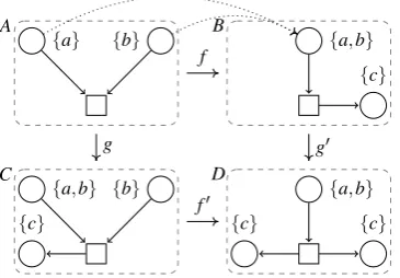
is a pushout of(f,g). An example of a pushout can be seen in Figure 1, where the morphisms are indicated by position with the exception of the two places inAwhich are non-injectively mapped to the same place inB. The pushout contains the elements of BandC, but merges elements related viaA, i.e. elements are merged if they share a common preimage inA. The labels of elements inDare thereby the supremum of the labels of all their preimages inBandC. Thus,Dcan be seen as the smallest merging ofBandCvia the interfaceA. We state the existence of pushouts and pushout complements in our setting by the following two lemmas.
A B
C D
{a} {b} {a,b}
{c}
{a,b} {b}
{c}
{a,b}
{c}
{c} f
g g′
f′
Figure 1: Example of a pushout using the lattice
(P({a,b,c}),⊆)as inscriptions.
A B
C D
{a}
{a,b} f
g′
Figure 2: Example morphisms, where no pushout complement exists
Lemma 2 For morphisms b∶A→B and d∶B→D the pushout complement in the category
CPN[In,⊑]exists, if and only if the following conditions hold:
• for every x∈PB∪TB without a preimage in A, d(x) is only connected to edges with a preimage in B (dangling edge condition),
• for every x,y∈PB∪TB∪EB, if d(x) =d(y) and x≠y, then x and y have preimages in A (identification condition), and
• for every x∈PB∪TB∪EB without a preimage in A, inB(x) =inD(d(x))holds (inscription condition).
The first two conditions ofLemma 2are well-known conditions for the existence of pushout complements for general graphs. The last condition is illustrated inFigure 2. The place in D cannot have a preimage inC, since the pushout ofBandCwould contain two places, but thenD is not minimal since the inscription would have to be{a}. Thus, no pushout complement exists in this case.
Note that pushout complements inCPN[In,⊑]are not necessarily unique, even if all involved morphisms are injective. We approach this ambiguity by introducing the notions of preservation-focused and deletion-preservation-focused rewriting. While the first one arises from a natural refinement of DPO rewriting, the latter notion prefers deletion to preservation when rewriting inscriptions and its application is illustrated in more detail inSection 3.
Definition 5(DPO Rule and Matching) A(DPO)⊑-ruleρ is a pair of⊑-morphismsl∶I→L
andr∶I→R. A⊑-matchof a ruleρto a netNis a⊑-morphismm∶L→N.
Definition 6 (Preservation-Focused Rewriting) Let l∶I→L and r∶I →R be a rule and let
m∶L→Nbe a match of the rule inN. A netNcan be rewritten to a netN′
if there is a minimal pushout complementC,m′∶
I→C,l′∶
C→Nsuch thatN′
is isomorphic to the pushout ofm′
and r. A pushout complementCis minimal if for all pushout complementsD,m′′∶I→D,l′′∶D→N
it holds that if there exists an injective⊑-morphismk∶D→Cwithm′=
k○m′′
andl′′=
l′○
We call a rule preservation-applicable, if at least one pushout complement exists.
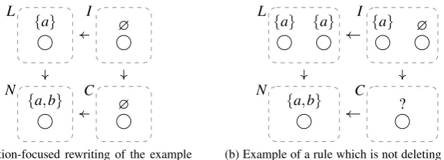
When using preservation-focused rewriting, inscriptions are rewritten in the classical DPO sense. A rule application tries to delete the ”difference” between an inscription in L and its preimage inI from its image inN. If this deletion is not possible, the deletion is not performed. However, the rule is still preservation-applicable (taking the conditions of Lemma 2 into ac-count), but the inscription remains unchanged, as demonstrated in the following example. Example1 Figure 3ashows the minimal pushout complement using the lattice(P({a,b}),⊆), since{b}is the smallest inscription such that{b}⊔{a} = {a,b}. The rule can simply delete the ’a’ part of the inscription{a,b}to obtain{b}. However, this is not always possible as shown in
Figure 3b, where the lattice inFigure 3cis used. This lattice does not contain{b}such that{a,b}
is now the minimal inscription. Effectively the inscription remains unchanged although the rule specifies a (partial) deletion. Note thatFigure 3bis also a pushout complement if(P({a,b}),⊆)
is used, although it is not minimal in that case.
L I
N C
{a} ∅
{a,b} {b}
(a) The minimal pushout complement us-ing the lattice(P({a,b}),⊆)
L I
N C
{a} ∅
{a,b} {a,b}
(b) The minimal pushout complement us-ing the lattice shown inFigure 3c
{a,b}
{a}
∅
(c) Hasse diagram of a lattice
Figure 3: A preservation-focused rule application using two different (distributive) lattices
In general a preservation-focused rewriting step generates a set of rewritten nets, but we can state the following uniqueness criterion.
Proposition 1 Letρbe a⊑-rule where the left leg is injective and let m be a⊑-match such that ρ is preservation-applicable to some net N. The preservation-focused application ofρ to N via m results in a unique net N′
(up to isomorphism) if the set of inscriptions of N is a disjoint union of lattices and each lattice is meet-infinite distributive.
Definition 7 (Forgetful functor) Let F∶CPN[In,⊑] →CPN[In,=] be a functor. For every objectA= (PA,TA,EA,In,cA,inA)ofCPN[In,⊑] we define F(A) = (PA,TA,EA,In,cA,in′A)with in′
A(x) = ⊓Πfor allx∈PA∪TA∪EA, whereinA(x) ∈Πfor some elementΠof the partitionΠInof In. For every arrowm∶A→Bwe defineF(m)(x) =m(x)for allx∈PA∪TA∪EA.
Definition 8(Deletion-Focused Rewriting) Letl∶I→Landr∶I→Rbe a rule and letm∶L→N be a match of the rule inN. A deletion-focused rewriting step is performed in the following way:
1. Calculate a pushout complement N′= (P
N′,TN′,EN′,In,cN′,inN′)ofF(l)andF(m)with
morphismsm′∶
F(I) →N′,
l′∶
N′→
F(N). 2. For everyx∈N′
let the set of inscriptionsIxbe defined as follows:
Ix= {z∈In∣ (∀x′∈I∶ (m′(x′) =x⇒z⊓inL(l(x′)) =inI(x′)))∧z⊑inN(l′(x))}.
IfIx is non-empty for allx∈N′, construct a net N′′= (PN′,TN′,EN′,In,cN′,inN′′) where
inN′′(x)is any maximal element ofIx and the morphismsm′′∶I→N′′,l′′∶N′′→Nwith
m′′(x) =m′(x),l′′(x) =l′(x).
3. Calculate the pushout ofm′′andrto obtain the rewritten Petri netM.
We call a rule deletion-applicable if the first two conditions ofLemma 2hold and for at least one netN′
calculated in the first step,Ixis non-empty for allx∈N′. By construction m′′ and
l′′ defined in Definition 8 are valid ⊑-morphisms and the diagram
l′′○
m′′=
m○lcommutes, but is not necessarily a pushout. The application condition differs from preservation-focused rewriting and arises from conflicts shown inFigure 4b.
L I
N C
{a} ∅
{a,b} ∅
(a) Deletion-focused rewriting of the example inFigure 3b
L I
N C
{a} {a} {a} ∅
{a,b} ?
(b) Example of a rule which is not deleting ap-plicable
Figure 4: Examples of deletion-focused rewriting steps
Example2 Figure 4ashows the deletion-focused rewriting step applied to the example in Fig-ure 3busing the lattice in Figure 3c. We search for every inscriptionz for which z⊓ {a} = ∅
holds and which is also smaller or equal to{a,b}. Since∅is the only possibility, it is a maximal element. Effectively, since there is no inscription containingbwithouta, the deletion ofafrom
rule specifies a preservation and a rewriting of the same inscription, such thatIxis empty for the
node inC. The node cannot be labelled with∅since thenm′′would not be a valid⊑-morphism.
Note that in this case a pushout complement does exist.
Although ambiguous in the general case, we can state a uniqueness criterion for deletion-focused rewriting which is analogue toProposition 1.
Proposition 2 Letρbe a⊑-rule where the left leg is injective and let m be a⊑-match such that ρis deletion-applicable to some net N. The deletion-focused application ofρ to N via m results in a unique net N′(up to isomorphism) if the set of inscriptions of N is a disjoint union of lattices
and each lattice is join-infinite distributive.
3
Deletion-focused PNML rewriting
The Petri Net Markup Language (PNML) is a well established XML-based format for making Petri net-based models persistent [HKK+
09]. Therefore, we use PNML in our implementation as basis for describing so-called reference nets [Kum02]. These are coloured Petri nets where the tokens are references to objects in a class hierarchy and also support code execution when firing transitions. We clarify how rewriting steps will be performed in this setting, by defining a mathematical model for XML below. This also illustrates how our rewriting formalisms can be implemented in practice.
In this setting, inscriptions are XML nodes, and hence have a tree-like structure. We will show that they form a disjoint union of lattices compatible with our rewriting formalisms. We assume that XML nodes are distinguishable by an ID (which can be the node name or a designated attribute) and the order on child nodes (but not the content of nodes) is negligible. Furthermore, every XML node has a value (possibly a tuple) which describes its properties, such as attributes, excluding child nodes. We use⊎to denote the disjoint union.
Definition 9 (XML Inscription) Let (Val,t) be a disjoint union of complete lattices Vali of values with⊎i∈IVali=Val and letN be a set of IDs, which is sorted such that it can be
parti-tioned inNi withN= ⊎i∈INi. An XML inscriptionxmlN,Val is a directed rooted tree(V,E,r,γ)
of finite height, where V is a set of vertices, E⊆V×V is a set of edges, r∈V is the root andγ ∶V → ⋃i∈I(Ni×Vali) maps properties to each vertex. Additionally for every two edges (v1,v2),(v1,v3) ∈Ewithγ(vi) = (ni,wi)(fori∈ {2,3}) it holds thatn2≠n3.
For everyv∈V we definev↓ = (V′,E′,v,
γ′)to be the subtree ofxmlN,Valwith rootv, which is an XML inscription itself.
Definition 10 LetXMLN,Valbe the set of all XML inscriptionsxmlN,Val. We define the ordered
set(XMLN,Val,⊑), where for two elements(V1,E1,r1,γ1) ⊑ (V2,E2,r2,γ2)holds if and only if: let
γi(ri) = (ni,wi)fori∈ {1,2}, thenn1=n2,w1tw2, and for allv1∈V1with(r1,v1) ∈E1there is a
v2∈V2with(r2,v2) ∈E2such thatv1↓ ⊑v2↓.
The proof ofLemma 3is based on the following observations: each latticeInwithinXMLN,Val consists of all inscriptions, where the ID of the root elements are equal. The supremum exists if and only if this is the case and can be computed inductively as follows. LetL⊆Inbe a non-empty subset ofInwhere root elements have IDk. For every IDn∈N, we defineC⊔
n(L) = {v↓ ∣
(V,E,r,γ) ∈L,(r,v) ∈E,γ(v) = (n,w)}, the set of all direct subinscriptions of inscriptions ofL, where the root ID isn. Furthermore, letM= {n∈N∣C⊔
n(L) ≠ ∅}be the set of all IDs for which child nodes exist and let (Vm,Em,rm,γm) = ⊔Cm⊔(L) be their supremum for each m∈M. The supremum ofLcan be expressed as follows:
⊔L= ({x}⊎ ⊎ m∈M
Vm,{(x,v) ∣v∈ {rm∣m∈M}}⊎ ⊎ m∈M
Em,x,γ′),
whereγ′(y) =γm(y)fory∈Vmandγ′(x) = (k,l∈Lwl)withl= (Vl,El,rl,γl)andγl(rl) = (k,wl).
The infimum can be expressed in an analogous way, with the exception thatC⊓
n(L) =Cn⊔(L)if everyinscription ofLhas a child with IDnandC⊓
n = ∅otherwise.
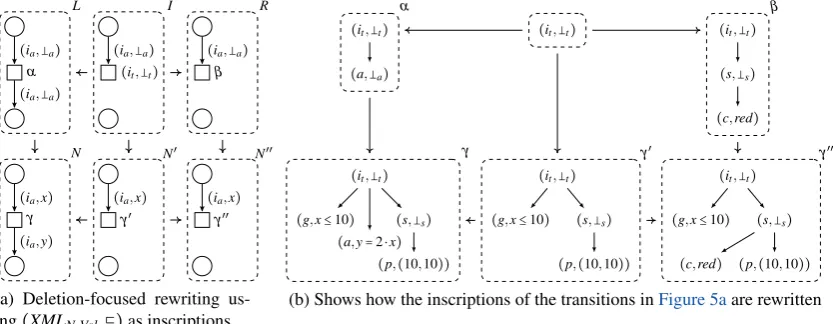
Example3 To illustrate the use of(XMLN,Val,⊑), we give a complete deletion-focused rewriting
step in Figure 5. The rule as well as the rewritten nets are show in Figure 5a. For clarity, the inscriptions of the shown transitions are displayed separately in Figure 5b. Inscriptions of arcs have a root IDia and either a variable (x ory) or no variable (a with x,y⊒ a) as value.
Root elements of inscriptions of transitions have always the IDit and valuet, but have a more
complex substructure. This can consist of a guard conditiong(a boolean expression preventing firing), an actiona(assigning the result of an arithmetic to a variable when firing) and a styles
(describing the visual appearance). The style can consist of a positionpand a colourc.
(ia,a)
(ia,a) α
L
(ia,a)
(it,t) I
(ia,a) β
R
(ia,x)
(ia,y) γ
N
(ia,x) γ′
N′
(ia,x) γ′′
N′′
(a) Deletion-focused rewriting us-ing(XMLN,Val,⊑)as inscriptions
(it,t)
(a,a) α
(it,t) (it,t)
(s,s)
(c,red)
β
(it,t)
(g,x≤10)
(a,y=2⋅x)
(s,s)
(p,(10,10)) γ
(it,t)
(g,x≤10) (s,s)
(p,(10,10)) γ′
(it,t)
(g,x≤10) (s,s)
(p,(10,10))
(c,red)
γ′′
(b) Shows how the inscriptions of the transitions inFigure 5aare rewritten
Figure 5: Example of a deletion-focused rewriting of anXMLN,Val-coloured Petri net
The given rule can be matched to any netNthat contains a transition with one incoming arc, one outgoing arc, and an action with any value. In the first step, it deletes the outgoing arc and the action to generate the netN′
. The inscriptionγ′is the largest inscription satisfyingγ′⊓α= (it,t)
well. Note thatN′
is not a pushout complement (which does not exist), since the inscription of the deleted arc is strictly larger than its preimage inL, thus, the rule is not preservation-applicable toN. In the second step, the pushoutN′′
is generated by calculating the supremumγ′′=γ′⊔β, which contains all merged subinscriptions of bothγ′andβ. The value ofit inγ′′is generated by
the supremum of its values inγ′andβ, i.e. byt⊔t= t (the same holds fors). Effectively the
transition is marked with the colour red, without changing other layout properties.
In addition to the previous result, we can show that our approaches rewrite uniquely, if the lattices of values are meet-infinite or join-infinite distributive.
Lemma 4 Every lattice of(XMLN,Val,⊑)is meet-infinite (or join-infinite) distributive, if every lattice of Val is meet-infinite (or join-infinite) distributive.
4
Application to User Interface Reconfiguration
Adaptable UIs offer a great benefit to human-computer interaction, according to the fact that those UIs can be adapted to the user’s personal preferences and abilities. The use of a formal modelling approach in this context offers the opportunity to close the gap between modelling and execution of UIs on the one hand and the implementation of adaptable UIs in a full-fledged computer-processable format on the other. Based on a two-layered representation of a UI, we developed a visual modelling language for interactive modelling of interaction logic by experts. Interaction logic can be defined as a data processing layer, modelling data-based communication between the physical representation and the system to be controlled. The physical representation is the second layer of the UI that directly interacts with the user and can be specified as a set of widgets, such as buttons, sliders, or text fields, etc. In the interaction logic, events are being pro-cessed that occur after, e.g., the user pressed a button or after he used another interaction element of the physical representation. Vice versa, data emitted from the underlying system is prepared to be presented to the user via the physical representation. Beside this data-based communica-tion between user and system (also called business logic), also dialogue-specific structures are specified in interaction logic. Here, data-based dependencies between input events and system data can influence interaction by predefined logic conditions.
For visually modelling, a graph-based visual language called FILL [Wey12] has been devel-oped, that is transformed into reference nets as introduced by Kummer [Kum02]. The reason for this is motivated by various aspects, such as that the transformation defines a formal semantic for FILL, reference net-based interaction logic is executable using the implemented open-source simulator RENEW [KWD], and finally, interaction logic is accessible for formal graph rewriting concepts, as described in the paper at hand. Thus, based on this transformation and the rewriting approaches introduced, the full-fledged concept required for the development of formal adaptable UIs is provided.
For modelling user interfaces using FILL, a visual and interactive editor has been developed, called UIEditor1. The editor is separated into two visual editors to (a) model the physical repre-sentation of a visual user interface and (b) to model interaction logic using FILL. For execution
1
of the user interface model, the UIEditor offers a simulation component, which is also capable to transform FILL models into reference nets. Thus, a computer parseable representation of such a reference net has to be provided. We decided to use PNML, which is the main reason for ap-plying the lattice-extended rewriting approach to PNML inSection 3. The whole transformation algorithm has been described in [Wey12, pg. 44–84]. A third component implements interactive reconfiguration, as it will be described in more detail, below, which is responsible for interac-tively creating rewriting rules. This interactive creation is the major aspect of implementing adaptable user interfaces, since the engineer modelling the UI is not able to foresee all possible adaptations a user could have in mind. Hence, the changes in the UI – both in the physical repre-sentation and the interaction logic – should be controlled by the user and need not be predefined by the application provider (although this is also possible).
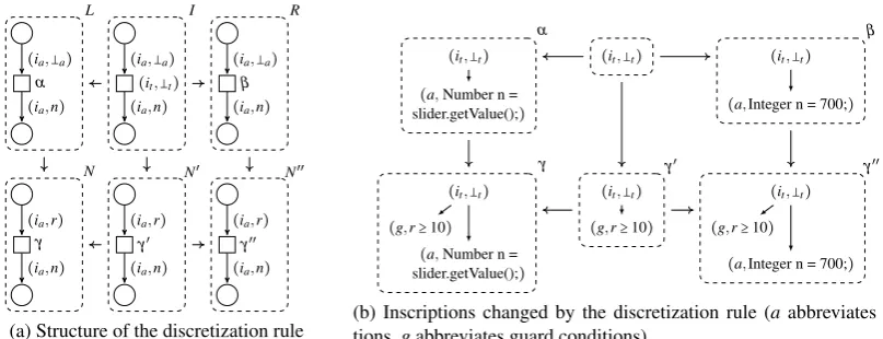
Using graph transformation to change interaction logic, the behaviour of a given user interface can be adapted to certain requirements. Paired with the ability of reference nets to be executed based on simulation, the changes can be directly tested and used in an application scenario. For instance, in [WBLK12] such an scenario has been described, where users were asked to recon-figure an initially given user interface of a simple simulation of a steam water reactor according to a variety of trained control tasks. These tasks were embedded to a controlling scenario of the reactor simulation. Here, the user has to start and stop the reactor, or to handle upcoming system errors, such as the blackout of a water pump. In a test run, two groups were asked to perform these tasks in a predefined test scenario [BWKL13]. The experiment group was able to interactively reconfigure the user interface by choosing from a predefined set of operations, where the control group did not have this option. The users were able to combine various buttons to one, which was able to perform all operations in parallel, that were former triggered by the selected buttons. Furthermore, users were able to discretize a continuous input operation, e.g., represented as a slider widget. For instance, a user can select a slider, chose the discretization op-eration, and define the discrete integer value that should be settable by a newly generated button. The rewriting rule generated for such an adaptation is shown inFigure 6, including an exemplary rule application.
(ia,a)
(ia,n) α
L
(ia,a)
(ia,n)
(it,t) I
(ia,a)
(ia,n) β
R
(ia,r)
(ia,n) γ
N
(ia,r)
(ia,n) γ′
N′
(ia,r)
(ia,n) γ′′
N′′
(a) Structure of the discretization rule
(it,t)
(a,Number n = slider.getValue();)
α
(it,t) (it,t)
(a,Integer n = 700;) β
(it,t)
(g,r≥10)
(a,Number n = slider.getValue();)
γ
(it,t)
(g,r≥10) γ′
(it,t)
(g,r≥10)
(a,Integer n = 700;) γ′′
(b) Inscriptions changed by the discretization rule (aabbreviates ac-tions,gabbreviates guard conditions)
All reconfiguration operations were applied to reference net-based interaction logic using deletion-focused PNML rewriting in a two step process. In the first step, the user interactively se-lected the interaction elements that should be affected (e.g. the slider), as well as the reconfigura-tion operareconfigura-tion (e.g. discretizareconfigura-tion) that should be applied. The second step has been implemented algorithmically and was responsible for selecting the affected graphical parts of interaction logic (e.g. the button) and generating the XML-based graph rewriting rule, containing all parts to be changed and being applied to interaction logic afterwards. In Figure 6a the resulting rule of the discretization operation can be seen where the inscriptions are showFigure 6b. Here, the lattice uses class inheritance to define a rule pattern which can match various number types in the inscription, such as Double or Integer. The new transition generates a specific integer value implementing the functionality of the new button, while the guard condition remains unchanged, since it was not specified to change by the rule.
5
Conclusion
By adding an order on the inscriptions, we introduced two rewriting formalisms for coloured Petri nets, which are also able to (partially) change inscriptions. The first formalism is a straight-forward extension of the classical DPO approach, while the second formalism tries to add an SPO-like behaviour on the inscriptions, still providing the same behaviour on the net structure. The latter approach has similarities with the so called Sesqui Pushout approach introduced in [CHHK06], where the left leg of a rule is not applied by calculating the pushout complement, but the final pullback complement. The main difference is that all incident edges are cloned in SqPO, if a node is split by a rule. Further, there are rules, where our deletion-focused rewriting will be ambiguous while SqPO is not applicable due to the fact that the final pullback comple-ment is unique if it exists. Our approach is similar to [PEM87] while correcting a minor error already mentioned in [HP02], coming from incorrect conditions for the existence of pushout complements. In Section 3 and 4 we introduced a disjoint union of lattices compatible with our formalisms and illustrated how the UIEditor uses this formalisms to realize adaptive user interfaces. I this context the approach of [LO04] could be interesting, where the application of transformation rule may depend on the current marking of the net.
Although out of the possibilities of this paper, it is not difficult to introduce typical extensions of the DPO approach into our approach, for instance negative application conditions. Further-more, its extension to other types of labelled graphs is quite straightforward.
Acknowledgements: We thank Barbara K¨onig for the helpful discussion on lattice theory and
its possible application in our setting.
Bibliography
[Bir67] G. Birkhoff.Lattice Theory. American Mathematical Society, 1967.
[CHHK06] A. Corradini, T. Heindel, F. Hermann, B. K¨onig. Sesqui-pushout rewriting. InProc. of ICGT ’06. Pp. 30–45. Springer, 2006. LNCS 4178.
[CMN80] S. K. Card, T. P. Moran, A. Newell. The keystroke-level model for user performance time with interactive systems.Communications of ACM23:396–410, 1980.
[EHP06] H. Ehrig, K. Hoffmann, J. Padberg. Transformations of Petri Nets. Electr. Notes Theor. Comput. Sci.148(1):151–172, 2006.
[HJSW10] F. Heidenreich, J. Johannes, M. Seifert, C. Wende. Closing the Gap between Mod-elling and Java. In Software Language Engineering, LNCS 5969. Pp. 374–383. 2010.
[HKK+09] L. M. Hillah, E. Kindler, F. Kordon, L. Pertrucci, N. Tr`eves. A primer on the Petri
Net Markup Language and ISO/IEC 15909-2. InPetri Net Newsletter. Volume 76. Gesellschaft f¨ur Informatik, Bonn, 2009.
[HP02] A. Habel, D. Plump. Relabelling in Graph Transformation. InProc. of ICGT ’02. Pp. 135–147. Springer, 2002. LNCS 2505.
[Jen97] K. Jensen.Coloured Petri Nets: Basic Concepts, Analysis Methods and Practical Use. Vol 1, Basic Concepts. Springer, 1997.
[JWZ93] C. Janssen, A. Weisbecker, J. Ziegler. Generating user interfaces from data models and dialogue net specifications. InProc. of INTERACT ’93 and CHI ’93. CHI ’93, pp. 418–423. ACM, New York, NY, USA, 1993.
[KP85] D. Kieras, P. G. Polson. An approach to the formal analysis of user complexity. International Journal of Man-Machine Studies22(4):365–394, 1985.
[Kum02] O. Kummer.Referenznetze. Logos, 2002.
[KWD] O. Kummer, F. Wienberg, M. Duvigneau. Renew—The Reference Net Workshop, online, URL:http://renew.de/(last visited: 30-10-2013).
[LO04] M. Llorens, J. Oliver. Introducing Structural Dynamic Changes in Petri Nets: Marked-Controlled Reconfigurable Nets. In Wang (ed.),Automated Technology for Verification and Analysis. LNCS 3299, pp. 310–323. Springer Berlin, 2004.
[NPLB09] D. Navarre, P. Palanque, J.-F. Ladry, E. Barboni. ICOs: A model-based user in-terface description technique dedicated to interactive systems addressing usability, reliability and scalability.ACM TOCHI16(4):1–56, 2009.
[PEM87] F. Parisi-Presicce, H. Ehrig, U. Montanari. Graph rewriting with unification and composition. In Proceedings of the 3rd Int’l Workshop on Graph-Grammars and Their Application to Computer Science. Pp. 496–514. Springer, 1987.
[Roz97] G. Rozenberg (ed.).Handbook of graph grammars and computing by graph trans-formation: volume I. foundations. World Scientific Publishing, 1997.
[SW14] J. St¨uckrath, B. Weyers. Lattice-extended Coloured Petri Net Rewriting for Adapt-able User Interface Models. Technical report 2014-01, Abteilung f¨ur Informatik und Angewandte Kognitionswissenschaft, Universit¨at Duisburg-Essen, 2014.
[WBLK12] B. Weyers, D. Burkolter, W. Luther, A. Kluge. Formal modeling and reconfiguration of user interfaces for reduction of errors in failure handling of complex systems. Human-Computer Interaction28(10):646–665, 2012.