BULGARIAN ACADEMY OF SCIENCES
CYBERNETICS AND INFORMATION TECHNOLOGIES • Volume 10, No 1 Sofia • 2010
Open Access to Call and Session Control in Mobile Networks
Evelina Pencheva, Ivaylo Atanasov
Technical University of Sofia, 1794 SofiaE-mails: [email protected] [email protected]
Abstract: The paper presents a study on implementation aspects of a server,
providing application programming interfaces to functions for call control and data session control in mobile networks. The value-added service logic in mobile networks is provided on Customized Application for Mobile services Enhanced Logic (CAMEL) platform. We suggest an approach to modeling the server behavior that supports Open Service Access (OSA) interfaces of and “talks” CAMEL Application Part (CAP) protocol toward the network. The approach is presented in a formal way as labeled transition system which corresponds to the model representing the application view on the behavior of call and data session objects. It is proved by bisimulation relation between the labeled transition systems that the suggested call state model and data session state model for the control protocol expose equivalent behavior compared with those of the standardized call and data session state models as seen by OSA applications.
Keywords: Open service access, call control, data session control, labeled
transition systems, behavioral equivalence.
I. Introduction
Open Service Access (OSA) is an open interface that allows third party applications to invoke communication functions in a public network. Network functions accessed by applications are called Service Capability Features (SCF) [1]. Application programming interfaces are defined for each OSA SCF exposed toward the applications. The OSA Generic Call Control SCF provides functions for simple call control which allows to setup traditional two-party calls [2]. The OSA Data
Session Control SCF allows setting up, releasing, and managing packet data sessions [3].
The SCF interface toward the network is independent of the application logic, i.e., the sequence of method invocation and responses is network independent. This interface independence is one of the problems in deploying OSA in convergent networks. There are no standards for the SCF interfaces toward the network, which can be based on Session Initiation Protocol (SIP), Customized Application for Mobile services Enhanced Logic Application Part (CAP), Intelligent Network Application Part (INAP), Megaco, etc. The network element that provides OSA interfaces toward applications and control protocols toward the network is called Service Capability Server (SCS). It is considered as a special type of application server. The OSA SCS deployed in mobile networks must support CAP protocol and has to realize session state models that correspond both to the application view and control protocol. Fig.1 shows the deployment of OSA SCS in CAMEL network.
For each call a Basic Call State Model (BCSM) at the Mobile services Switching Center (MSC) is triggered [4]. The OSA SCS needs to maintain a call state model that corresponds to the OSA application view of the call object. While the BCSM and model, representing the application view on call states, are standardized, there are no recommendations for the call state model in the OSA SCS which is regarded to be an implementation issue.
The packet session state is monitored at the Serving GPRS Support Node (SGSN). The OSA SCS has to maintain a session state model that corresponds to both the packet session state at the SGSN and application view on data session object. Instead of standardizing the behavior of OSA SCS, the Third Generation Partnership Project (3GPP) provides only mapping of OSA Data Session Control interfaces onto CAP protocol [5]. A mapping of OSA Generic Call Control interfaces onto CAP protocol is also available [6].
Some publications [7, 8], concerning OSA SCS implementation, focus on aspects related to the application programming interfaces, while other authors [9, 10] discuss evaluation of conformance of the basic call and session control mechanisms in the network out of the application context.
Our research aims to suggest an approach to modeling call and data session states in an OSA SCS. The call and data session state models have to expose equivalent behavior to that of the corresponding OSA interface objects as seen from application point of view. To prove the behavior equivalence we present the suggested state models in a formal way as Labeled Transition Systems (LTS) and use the concepts of bisimulation and homomorphism [11].
The rest of the paper is organized as follow. Section II briefly introduces the necessary notational background for labeled transition systems and behavioral equivalences. Section III presents an approach to modeling the originating and terminating call states that conforms to the OSA application view of a two party call. A model that represents the call states in case of application initiated call is described. Section IV presents an approach to modeling the packet session states that is synchronized with the application view on the data session object. Having in mind the implicit behavioral recommendations which are based on the available
mapping of OSA interface class methods onto CAP messages, we provide adequate conditions on transformations in order to preserve the logic equivalence. The paper is concluded by sketching out an approach to modeling the session states in IP-based multimedia networks.
Fig.1. Deployment of OSA in circuit- and packet-switched mobile networks
II. Labeled transition systems and behavioral equivalence
Definition 1. A Label Transition System (LTS) is a quadruple (S, Аct, →, s0),
where:
S is countable set of states,
Act is a countable set of elementary actions,
→⊆S ×Act × S is a set of transitions, and
s0 ∈S is the set of initial states.
A labeled transition system (S, Аct, →, s0) is called finitely branching, if for
any state s∈S, set {(а, s′), a∈ Act | (s, a, s′) ∈→} is finite. The labeled transition systems we consider in the paper are only labeled transition systems that are finitely branching.
We will use the following notations:
s
→
а s′ stands for the transition (s, a, s′);s а
→
means that ∃s′: s а→
s′; Application OSА SCS MSC SGSN CAP CAP Basic Callstate model Packet session state model OSA application programming interfaces
Call state
s
μ
⇒
sn, where μ = а1, а2, ..., аn : ∃s1, s2, …, sn, such that s⎯
⎯→
1a s1...
⎯→
⎯
an sn; s μ⇒
means that ∃s′, such as sμ
⇒
s′;⇒
μˆ means ⇒ if μ ≡ τ orμ
⇒
otherwise.Definition 2. Let Т= (S, Аct, →, s0) and Т ′ = (S′,Аct, →, s0′) are two labeled
transition systems. Then
h: S→S′ is a root preserving map if h (s0) = s0′;
A root preserving map is surjective if h(S) = S′.
Definition 3. Let Т= (S, Аct, →, s0) and Т ′ = (S′, Аct, →′, s0′) are two labeled
transition systems.
h: S→S′ is a transition system homomorphism if h(s0) = h(s0′) and h(→)⊆→′,
where h(→) = {h(s) а
→′
h(s′) | s а→
s′}; a homomorphism is surjective if h(S) = S′.Definition 4. A strong bisimulation between two transition systems
Т = (S, Аct, →, s0) and Т ′ = (S′, Аct, →, s0′) is a binary relation U⊆S×S′, such that:
s0 U s0′;
∀s∈S ∃s′∈S′: s U s′ and ∀s′∈S′ ∃s∈S: s U s′; if s U t, then ∀ а ∈ Act:
• s
→
а s′ implies ∃ t′: t→
а ′t′ and s′ U t′;• t
→
а ′t′ implies ∃s′: s→
а s′ and s′ U t′.The labeled transition systems T and T’ are bisimilar if there is a bisimulation between them.
Definition 5. Let Т = (S, Аct, →, s0) and Т ′ = (S′, Аct, →, s0′) are two labeled
transition systems. The relation h: S → S′ is called abstraction homomorphism if h
is a surjective transition system homomorphism satisfying the following:
∀ s1 ∈ S, а∈Act and s2′ ∈ S′, h(s1) а
→
′ s2′ implies ∃ s2∈ S: s1 а→
s2 and h(s2)=s2′.The following statement is true for two labeled transition systems:
Theorem 1. Two labeled transition systems are bisimilar iff they have a
The strong bisimulation possesses strong conditions for equivalence which are not always required. For example, there may be internal activities that are not observable. The strong bisimulation ignores the internal transitions.
Definition 6. Two labeled transition systems T = (S, A, →, s0) and T′ = (S′, A,
→′, s0′) are weekly bisimilar if there is a binary relation U ⊆ S×S′ such as if s1U t1:
s1 ⊆S and t1⊆S′ then ∀a ∈ Act:
s1
⇒
a s2 implies ∃t2: t1⇒′
aˆ t2 and s2U t2; t1⇒′
a t2 implies ∃s2: s1⇒
aˆ s2 and s2U t2.III. Call state models
The Application Server (AS) that hosts OSA applications can play different roles. For example, acting as a proxy server provisioning call baring services, the AS receives incoming request and proxies it back to the MSC which then forwards it toward the destination. Another case is in the context of an alarm call when the AS generates a request and sends it to the MSC which then forwards it toward destination.
First, we will consider the case when the application provides control on network initiated call.
A. Application control on terminating and originating parties
If the application logic is applied for the originating party, the OSA SCS needs to maintain a call state model that corresponds to the CAMEL Originating-Basic Call State Model (O-BCSM). If the application logic is applied for the terminating party, the OSA SCS needs to maintain a call state model that corresponds to the CAMEL Terminating-Basic Call State Model (T-BCSM).
A model representing the OSA application view on a call object is defined in [2]. According to this model, the call can be in one of the following states: Null
(no call), NoParty (call object exists with no party connected), 1PartyInCall (one party in call), 2PartiesInCall (established call with two parties), NetworkReleased
(call is terminated in the network and the application can only gather call information), Finished (call is terminated in the network and no call information can be gathered), ApplicationReleased (the call is terminated by the application). From call control point of view, there is no difference between the Null and NoParty
states, as they reflect specifics of object-oriented technology. In the
NetworkReleased, Finished and ApplicationReleased states, there are no parties connected to the call, hence from the call control point of view, these states can be labeled with the same label NullGCC.
Let us denote by ТGCC = (SGCC, АctGCC, →GCC, s0) a labeled transition system
SGCC = {NullGCC, 1PartyInCall, 2PartiesInCall };
ActGCC= {callEventNotify, connectionToCalledPartyUnsuccessful, answer,
release, callEnded};
→GCC = { NullGCC callEventNotify 1PartyInCall,
1PartyInCall connectionToCalledPartyUnsuccessful NullGCC,
1PartyInCall answer 2PartiesInCall, 2PartiesInCall release NullGCC,
2PartiesInCall callEnded NullGCC,
1PartyInCall callEnded NullGCC};
s0 = {NullGCC}.
The T-BCSM consists of four states in which service logic can interfere the processing of the terminating party. In T-Null state, the terminating party is idle, and the authority to route the call to the terminating party is verified, (e.g. business group restrictions, restricted incoming calls, or bearer capability compatibility). In
TermCallHandling state, terminating resource is informed of incoming call, an indication is sent to the O-BCSM that the terminating party is alerted, and the call is waited to be answered. In T-Active state, the connection is established between originating and terminating party. Default handling of the exception condition is being provided in T-Exception state.
Let us denote by ТTBCSM = (STBCSM,АctTBCSM, →TBCSM, s0′) a labeled transition
system, representing the CAMEL T-BCSM where:
STBCSM = {T-Null, TerminatingCallHandling, T-Active, T-Exception};
ActTBCSM= {TerminatingAttemptAuthorized, Tanswer, Tdisconnect, Tabandon,
Tbusy, TnoAnswer, releaseResources};
→TBCSM = { T-Null TerminatingAttemptAuthorized TerminatingCallHandling,
TerminatingCallHandling Tanswer T-Active, TerminatingCallHandling Tabandon T-Null, T-Active Tdisconnect T-Null,
TerminatingCallHandling Tbusy T-Exception, TerminatingCallHandling TnoAnswer T-Exception, T-Exception releaseResources T-Null};
s0′= {T-Null}.
The O-BCSM consists of four states in which service logic can interfere the processing of the originating party. In O-Null state, the originating party is idle, the authority/ability to place the call with given properties (e.g. bearer capability, subscription restrictions) is verified, and initial information package/dialing string (e.g. service codes, prefixes, dialed address digits) is collected from originating party. In О-Alerting state, information is analyzed and/or translated according to the dialing plan to determine routing address and call type, routing address and call type are interpreted, the next route is selected, and the originating party waits for the terminating party to answer. In O-Active state, the connection is established between originating and terminating parties. Default handling of the exception condition is being provided in the O-Exception state.
Let us denote by ТOBCSM = (SOBCSM,АctOBCSM, →OBCSM, s0′′) a labeled transition
SОBCSM = {О-Null, AnalysisRoutingAlerting, О-Active, О-Exception;
ActОBCSM= {CollectedInfo, Oanswer, Odisconnect, Oabandon, Obusy, OnoAnswer,
releaseResources};
→ОBCSM = { O-Null CollectedInfo AnalysisRoutingAlerting,
AnalysisRoutingAlerting Oanswer O-Active, AnalysisRoutingAlerting Oabandon O-Null, O-Active O_disconnect O-Null,
AnalysisRoutingAlerting Obusy O-Exception, AnalysisRoutingAlerting OnoAnswer O-Exception, O-Exception releaseResources O-Null};
s0′′= {О-Null}.
Proposition 1. The labeled transition systems ТGCC, ТТBCSM and ТТBCSM are
bisimular.
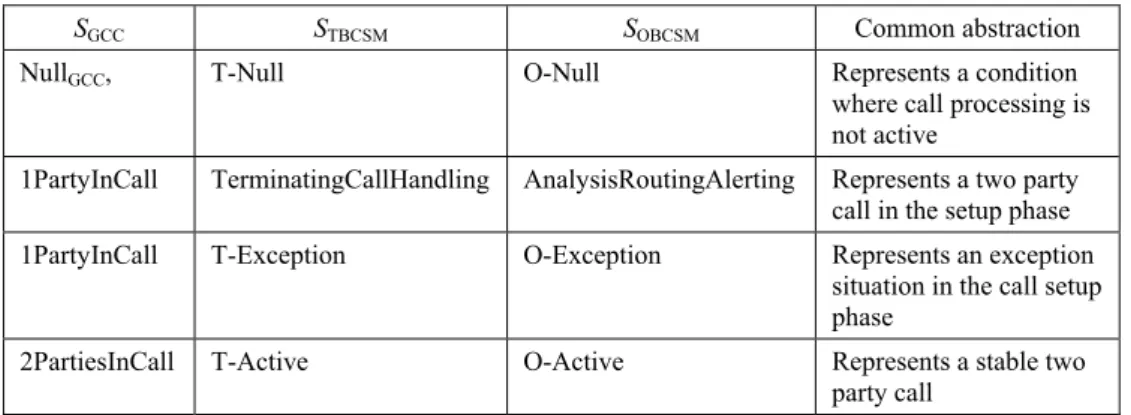
P r o o f. To prove that the systems expose equivalent observable behavior, it has to be found a common image under abstraction homomorphism. The homomorphism between the states of ТGCC,ТТBCSM and ТТBCSM is shown in Table 1,
and the transition homomorphism is shown inTable 2. The state homomorphism is based on the common abstraction they represent, while the transition homomorphism is based on the mapping of OSA Generic Call Control interface methods onto CAP messages.
Table 1 State homomorphism forТGCC,ТТBCSM and ТТBCSM
SGCC SТBCSM SОBCSM Common abstraction
NullGCC, T-Null О-Null Represents a condition where call processing is not active
1PartyInCall TerminatingCallHandling AnalysisRoutingAlerting Represents a two party call in the setup phase 1PartyInCall T-Exception О-Exception Represents an exception
situation in the call setup phase
2PartiesInCall T-Active О-Active Represents a stable two party call
Having the presented homomorphism, it can be formally deduced that ТGCC,
ТТBCSM and ТТBCSM are bisimilar, i.e., they expose equivalent behavior.
It has to be noted, that in the formal definitions of ТGCC,ТТBCSM and ТТBCSM
systems, the transitions related to route failure and connection failure are not included for simplicity. The refinement of the model with those transitions does not change the proof of behavioral equivalence because a common abstraction for those transitions also can be identified following the mapping in [5].
B. Application-initiated call
In case of application initiated call, the application connects both parties to the call. In this case, when the application creates the call object, it can request routing of the call to the remote party indicated by the target address. The call object moves to the
RoutingToDestination state where the application waits for answer from the remote party.
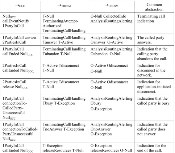
Table 2. Transition homomorphism forТGCC,ТТBCSM and ТТBCSM
→GCC →ТBCSM →OBCSM Common abstraction NullGCC callEventNotify 1PartyInCall T-Null TerminatingAttempt-Authorized TerminatingCallHandling O-Null CollectedInfo
AnalysisRoutingAlerting Terminating call indication
1PartyInCall answer
2PartiesInCall TerminatingCallHandling Tanswer T-Active AnalysisRoutingAlerting Oanswer O-Active The called party answers. 1PartyInCall callEnded NullGCC TerminatingCallHandling Tabandon T-Null AnalysisRoutingAlerting Oabandon O-Null
Indication that the calling party abandons the call. 2PartiesInCall
callEnded NullGCC,
T-Active Tdisconnect
T-Null O-Active Odisconnect O-Null Indication for disconnect in the network. 2PartiesInCall release NullGCC T-Active Tdisconnect T-Null O-Active Odisconnect O-Null Indication for application-initiated disconnect. 1PartyInCall connectionTo- CalledParty-Unsuccessful NullGCC TerminatingCallHandling Tbusy T-Exception AnalysisRoutingAlerting Obusy O-Exception
Indication that the called party is busy.
1PartyInCall connectionToCalled-PartyUnsuccessful NullGCC
TerminatingCallHandling
TnoAnswer T-Exception AnalysisRoutingAlerting OnoAnswer O-Exception
Indication that the called party does not answer. 1PartyInCall
callEnded NullGCC
T-Exception
releaseResources T-Null O-Exception releaseResources O-Null Indication for the end of the call.
Let us denote with ТGCC′ = (SGCC′, АctGCC′, →GCC′, s0′) a labeled transition
system representing the OSA application view on a call with two parties initiated by the application where:
SGCC′ = {NullGCC, RoutingToDestination, 1PartyInCall, 2PartiesInCall};
АctGCC′ = { routeReq, answer, connectionToCalledPartyUnsuccessful, release,
callEnded};
→GCC′ = {NullGCC routeReq RoutingToDestination,
RoutingToDestination answer 1PartyInCall, 1PartyInCall routeReq 1PartyInCall, 1PartyInCall answer 2PartiesInCall, 2PartiesInCall callEnded NullGCC,,
2PartiesInCall release NullGCC,
RoutingToDestination connectionToCalledPartyUnsuccessful NullGCC,
1PartyInCall callEnded NullGCC}; s0′= {NullGCC}.
In case of application-initiated call, the network considers both call parties as terminating. The call model in OSA SCS suggested by us is based on triggering of two T-BCSMs for each of the call parties.
Let us denote with Т = (SAPPCALL, АctAPPCALL, →APPCALL, s0′) a labeled transition
system representing the network model of an application-initiated call where:
SAPPCALL = {Null, TerminatingCallHandling′, 1Active, TerminatingCallHandling′′,
2Active, Exception};
ActAPPCALL= {TerminatingAttemptAuthorized1, answer1, disconnect, abandon, busy1,
noAnswer1, TerminatingAttemptAuthorized1, answer2, busy2,
noAnswer2, releaseResources};
→APPCALL = {Null TerminatingAttemptAuthorized1 TerminatingCallHandling′,
TerminatingCallHandling′ busy1 Exception,
TerminatingCallHandling′ noAnswer1 Exception,
TerminatingCallHandling′ answer1 1Active,
1Active TerminatingAttemptAuthorized2 TerminatingCallHandling′′,
TerminatingCallHandling′′ answer2 2Active,
2active Disconnect Null, 2active release Null,
TerminatingCallHandling′′ abandon Null, TerminatingCallHandling′′ busy2 Exception,
TerminatingCallHandling′′ noAnswer2 Exception,
Exception releaseResources Null}
s0′= {Null}.
Proposition 2. The labeled transition systems ТGCC′ and ТAPPCALL are bisimilar.
P r o o f. The common homomorphism abstraction for ТGCC′ and ТAPPCALL is
shown in Table 3 and Table 4 where the state and transition homomorphisms are presented correspondingly. The identified abstractions allow to deduce that ТGCC′
and ТAPPCALL are bisimilar.
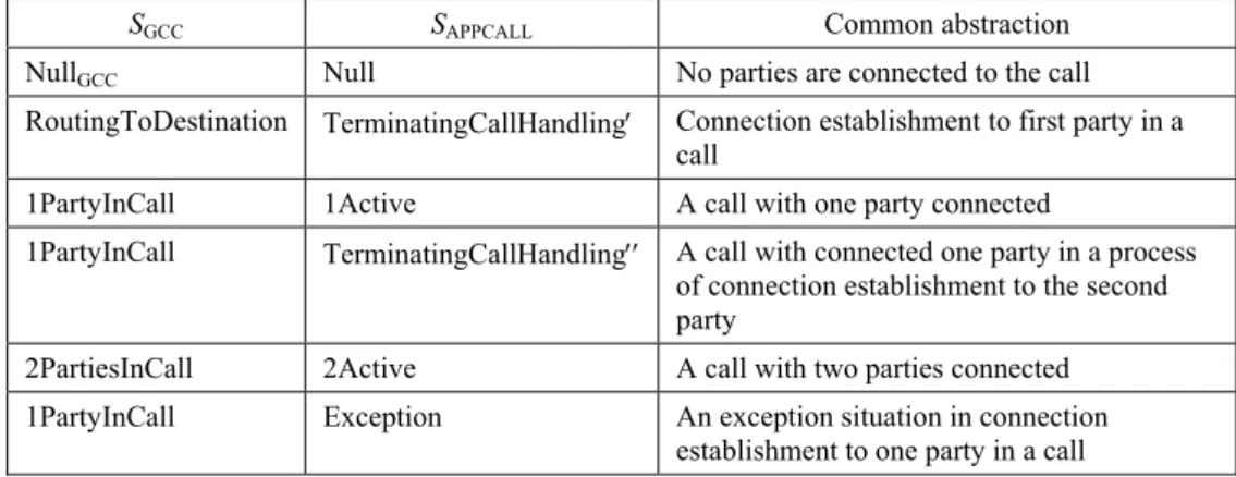
Table 3 State homomorphism forТGCC′and ТAPPCALL
SGCC SAPPCALL Common abstraction
NullGCC Null No parties are connected to the call RoutingToDestination TerminatingCallHandling′ Connection establishment to first party in a
call
1PartyInCall 1Active A call with one party connected
1PartyInCall TerminatingCallHandling′′ A call with connected one party in a process of connection establishment to the second party
2PartiesInCall 2Active A call with two parties connected 1PartyInCall Exception An exception situation in connection
IV. Data session state model
While the OSA Generic Call Control SCF provides open access to call control functions in circuit switched networks, the Data Session Control SCF provides access to functions for data session control in packet switched networks. In [3], a model representing the application view on data session states is defined. According to that model, the data session object can be in one of the following states. In Idle
state, the data session object is not created. The Setup state is entered when the
reportNotification method indicates that a data session, which the application is interested in, is setup. In Setup state, the application can request session establishment to the remote party by invoking connectReq method. In Established
state, the application is notified that the session is established. In NetworkReleased
state, the session is terminated and the application can gather session information. In ApplicationReleased state, the data session is terminated by the application. From data session control point of view, the Idle, Network released and Application released states are equivalent, as far as the data session is neither in establishing nor active phase.
Before data can be sent or received, a packet data protocol context (PDP context) for the user has to be established. The PDP context assigns an IP address for the communication and associates it with the user identities. The CAMEL PDP context state model represents the process of establishing PDP contexts for data communications. It is comparable to the O-BCSM and T-BCSM in CAMEL. Such model is triggered for each user which wants to participate in packet data session. The model consists of three states. In Idle state, there is no PDP context active (neither sending nor receiving data). A request to send or receive data causes a transition to PDP_context_setup state. When the SGSN is notified that the PDP context is set up, a transition to the PDP context_established state takes place. It is possible that while the user is sending or receiving data, he or she moves from one routing area to another. A direct transition form Idle state to
PDP_context_stablished state is possible during routing area update with SGSN change. A PDP can be deactivated either by request of the user or by the network, causing transition to Idle state. An exception situation during PDP context setup or in PDP context established state also results in transition to Idle state.
We suggest a session model that reflects both the application view on data session object and the CAMEL PDP context setup model.
Let us denote with ТDSC = (SDSC,АctDSC, →DSC, s0) a labeled transition system,
representing the OSA application view on data session state where:
SDSC = {IdleDSC, SetupDSC, EstablishedDSC};
ActDSC = {dataSessionSetup, dataSessionEstablished, connectReq, release,
dataSessionDisconnected, dataSessionSupervisionEvent};
→DSC = {IdleDSC dataSessionSetup SetupDSC,
SetupDSC connectReq SetupDSC
SetupDSC dataSessionEstablished EstablishedDSC,
IdleDSCdataSessionEstablished EstablishedDSC,
SetupDSCdataSessionDisconnected IdleDSC,
EstablishedDSCdataSessionDisconnected IdleDSC,
EstablishedDSCrelease IdleDSC
EstablishedDSC dataSessionSupervisionEvent EstablishedDSC}; s0 = {IdleDSC}.
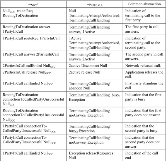
Table 4. Transition homomorphism forТGCC′ and ТAPPCALL
→GCC′ →APPCALL Common abstraction
NullGCC route Req
RoutingToDestination Null TerminatingAttemptAuthorized1 TerminatingCallHandling′
Indication of terminating call to the first party.
RoutingToDestination answer
1PartyInCall TerminatingCallHandlinganswer1 1Active ′
The first party in call answers.
1PartyInCall routeReq 1PartyInCall 1Active
TerminatingAttemptAuthorized1 TerminatingCallHandling′′
Indication of terminating call to the second party. 1PartyInCall answer 2PartiesInCall TerminatingCallHandling′′
answer2 2Active
The second party in call answers.
2PartiesInCall callEnded NullGCC 2active Disconnect Null Network-released call. 2PartiesInCall release NullGCC 2active release Null Application releases the
call. 1PartyInCall callEnded NullGCC TerminatingCallHandling′′
abandon Null
First party abandons the call RoutingToDestination connectionToCalledPartyUnsuccessful NullGCC TerminatingCallHandling′ busy1 Exception
Indication that the first party is busy RoutingToDestination connectionToCalledPartyUnsuccessful NullGCC TerminatingCallHandling′ noAnswer1 Exception
Indication that the first party does not answer 1PartyInCall
connectionTo-CalledPartyUnsuccessful NullGCC
TerminatingCallHandling′′
busy2 Exception
Indication that the second party is busy 1PartyInCall
connectionTo-CalledPartyUnsuccessful NullGCC
TerminatingCallHandling′′
noAnswer2 Exception
Indication that the second party does not answer
1PartyInCall callEnded NullGCC Exception releaseResources
Null Indication of the call end
The proposed session model includes two PDP context setup models for each party in the session. To distinguish between the two types of routing area change we use indexing. With ChangeOfPositionO1 we denote the transition when the
originating party changes the routing area and SGSN. With ChangeOfPositionO2 we
denote the transition when the originating party performs routing area update without SGSN change. The indexes for the mobility of the terminating party are similar.
Let us denote by ТPDP = (SPDP, АctPDP, →PDP, s0′) a labeled transition
SPDP = {IdlePDP, PDPcontextSetupO, PDPcontextEstablishedO,
PDPcontextSetupT, PDPcontextEstablishedT};
ActPDP = {PDPctxtEstablishmentО, PDPctxtAckО, disconnectO, exceptionO,
ChangeOfPositionCtxtO1,ChangeOfPositionCtxtO2,
PDPctxtEstablishmentТ, PDPctxtAckТ, disconnectT, exceptionT,
ChangeOfPositionCtxtT1, ChangeOfPositionCtxtT2}; →PDP = {IdlePDP PDPctxtEstablishmenO PDPcontextSetupO,
PDPcontextSetupO PDPctxtAckО PDPcontextEstablishedO,
PDPcontextSetupOexceptionО IdlePDP,
IdlePDP ChangeOfPositionCtxtO1 PDPcontextEstablishedO,
PDPcontextEstablishedOChangeOfPositionCtxtO2
PDPcontextEstablishedO,
PDPcontextEstablishedOexceptionО IdlePDP,
PDPcontextEstablishedOdisconnect IdlePDP,
PDPcontextEstablishedO PDPctxtEstablishmentТ PDPcontextSetupT,
PDPcontextSetupTexceptionТ IdlePDP,
PDPcontextSetupTChangeOfPositionCtxtO1 PDPcontextSetupT,
PDPcontextSetupTChangeOfPositionCtxtO2 PDPcontextSetupT,
PDPcontextSetupT PDPctxtAckТ PDPcontextEstablishedT,
PDPcontextEstablishedTChangeOfPositionCtxtT1 PDPcontextEstablishedT PDPcontextEstablishedT ChangeOfPositionCtxtT2 PDPcontextEstablishedT PDPcontextEstablishedT ChangeOfPositionCtxtО1 PDPcontextEstablishedT PDPcontextEstablishedT ChangeOfPositionCtxtО2 PDPcontextEstablishedT
PDPcontextEstablishedTexceptionТIdlePDP,
PDPcontextEstablishedTexceptionОIdlePDP,
PDPcontextEstablishedTdisconnect IdlePDP} s0′= {IdlePDP}.
Proposition 3. The labeled transition systems ТDSC, and ТPDP are weakly
bisimilar.
P r o o f. Let us build the relation U = SDSC× SPDP as
U = {(IdleDSC, IdlePDP), (SetupDSC, PDPcontextSetupO), (EstablishedDSC,
PDPcontextEstablishedT)}
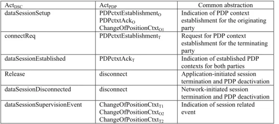
Given the mapping of Data Session Control interface methods onto CAP messages in [5], we build the following homomorphism relation h between ActDSC
and ActPDP, presented in Table 5.
Based on the common abstraction the related transitions can be labeled by the same labels. The proof that U is a weak bisimulation relation between the states of
TDSC and ТPDP follows from h(ActDSC) = ActPDP and the corresponding transition
Table 5. Homomorphism between ActDSCand ActPDP
ActDSC ActPDP Common abstraction
dataSessionSetup PDPctxtEstablishmentО PDPctxtAckO
ChangeOfPositionCtxtО1
Indication of PDP context establishment for the originating party
connectReq PDPctxtEstablishmentТ Request for PDP context establishment for the terminating party
dataSessionEstablished PDPctxtAckТ Indication of established PDP contexts for both parties
Release disconnect Application-initiated session
termination and PDP deactivation
dataSessionDisconnected disconnect Network-initiated session termination and PDP deactivation
dataSessionSupervisionEvent ChangeOfPositionCtxtT1 ChangeOfPositionCtxtО2 ChangeOfPositionCtxtT2
Indication of session related event
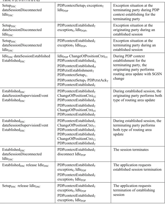
Table 6 Bisimulation relation between the states of TDSC and ТPDP
s1⇒ a s2 | s1, s2 ∈SDSC t1⇒′ aˆ t2 | t1, t2 ∈SPDP Abstraction IdleDSC dataSessionSetup SetupDSC IdlePDP PDPctxtEstablishmenO PDPcontextSetupO,
Indication of request for PDP context establishment for the originating party SetupDSC dataSessionEstablished EstablishedDSC PDPcontextSetupO PDPctxtAckО PDPcontextEstablishedO, PDPcontextEstablishedO ChangeOfPositionCtxtO2 PDPcontextEstablishedO PDPcontextEstablishedO PDPctxtEstablishmentТ PDPcontextSetupT, PDPcontextSetupT ChangeOfPositionCtxtO1 PDPcontextSetupT PDPcontextSetupT ChangeOfPositionCtxtO2 PDPcontextSetupT PDPcontextSetupT PDPctxtAckТ PDPcontextEstablishedT
PDP context establishment for the originating and terminating parties. During PDP context setup for the terminating party, the originating party can perform both types of routing area update
SetupDSC
dataSessionDisconnected IdleDSC
PDPcontextSetupO exceptionО IdlePDP,
Exception situation at the originating party during PDP context establishing for the originating party SetupDSC dataSessionDisconnected IdleDSC PDPcontextSetupTexceptionО IdlePDP,
Exception situation at the originating party during PDP context establishing for the terminating party SetupDSC dataSessionDisconnected IdleDSC PDPcontextSetupTdisconnect IdlePDP,
The originating party disconnects during PDP context setup for the terminating party
Table 6 (c o n t i n u e d) SetupDSC dataSessionDisconnected IdleDSC PDPcontextSetupT exceptionТ IdlePDP
Exception situation at the terminating party during PDP context establishing for the terminating party SetupDSC dataSessionDisconnected IdleDSC PDPcontextEstablishedТ exceptionО IdlePDP,
Exception situation at the originating party during an established session SetupDSC dataSessionDisconnected IdleDSC PDPcontextEstablishedТ exceptionТ IdlePDP,
Exception situation at the terminating party during an established session IdleDSCdataSessionEstablished EstablishedDSC IdlePDP ChangeOfPositionCtxtO1 PDPcontextEstablishedO, PDPcontextEstablishedO PDPctxtEstablishmentТ PDPcontextSetupT, PDPcontextSetupT PDPctxtAckТ PDPcontextEstablishedT During PDP context establishment for the terminating party, the originating party performs routing area update with SGSN change EstablishedDSC dataSessionSupervisionEvent EstablishedDSC PDPcontextEstablishedТ ChangeOfPositionCtxtO2 PDPcontextEstablishedТ PDPcontextEstablishedТ ChangeOfPositionCtxtO1 PDPcontextEstablishedТ
During established session, the originating party performs both type of routing area update
EstablishedDSC dataSessionSupervisionEvent EstablishedDSC PDPcontextEstablishedT ChangeOfPositionCtxtT1 PDPcontextEstablishedT PDPcontextEstablishedТ ChangeOfPositionCtxtT2 PDPcontextEstablishedТ
During established session, the terminating party performs both type of routing area update EstablishedDSC dataSessionDisconnected IdleDSC PDPcontextEstablishedТ disconnect IdlePDP
The session terminates
EstablishedDSCrelease IdleDSC PDPcontextEstablishedТ exceptionO IdlePDP PDPcontextEstablishedТ exceptionТ IdlePDP
The application requests established session termination
SetupDSCrelease IdleDSC PDPcontextEstablishedТ exceptionO IdlePDP PDPcontextEstablishedТ exceptionТ IdlePDP
The application requests termination of establishing session
V. Conclusion
The network interface of the OSA SCS is not standardized and it is regarded as implementation detail. There is a constraint for any implementations for a single point of contact. Instead of coordinating the connections in circuit-switched and packed-switched networks, the OSA SCS controls the interface to the underlying
network. In mobile networks, bearer connections rely on CAP signaling. Interfacing between application programming interfaces requests and responses, and CAP signaling, the OSA SCS needs to care for both side state machines – one for the interface objects and another for the CAP session.
The suggested approach to modeling the call and session states in an OSA SCS supports interfaces for generic call control and data session control. While the call state model corresponds to the CAMEL BCSMs, the session state model has to reflect the procedures concerning PDP context setup required for packet sessions. More refined models can be built considering different application server roles.
Following the same approach, session state models in IP-based multimedia networks might be designed. In such networks the establishment, modification and termination of sessions with more than two parties relies on SIP. Following the mapping of OSA Multiparty Call Control SCF onto SIP signaling, models for SIP session state for originating and terminating call legs can be designed.
By presenting the models in a formal way as label transition systems, the behavior equivalence is proved, using the concept of bisimulation.
Acknowledgement: The work is conducted under the grant of Project DO 02-135/2008 Research on
Cross Layer Optimization of Telecommunication Resource Allocation, funded by Bulgarian Ministry of Education and Science.
R e f e r e n c e s
1. H a n r a h a n, H u. Network Convergence, Services, Applications, Transport and Operations Support. Wiley, 2007.
2. 3GPP TS 29.198-4-2, v9.0.0, 2009, Open Service Access (OSA); Application Programming Interface (API) Part 2: Call Control Sub-part 2: Generic Call Control Service Capability Feature; (Release 9).
3. 3GPP TS 29.198-08, v9.0.0, 2009, Open Service Access (OSA); Application Programming Interface (API) Part 8: Data Session Call Control Service Capability Feature; (Release 9). 4. N o l d u s, R. CAMEL Intelligent Networks for GSM, GPRS and UMTS Networks. Wiley, 2006. 5. 3GPP TR 29.998-09, v9.0.0, 2009, Open Service Access (OSA); Mapping for Open Service
Access; Part 8, Data Session Control Service Mapping to CAP, (Release 9).
6. 3GPP TR 29.998-04-1, v9.0.0, 2009, Open Service Access (OSA); Mapping for Open Service Access; Part 4, Call Control Service Mapping; Subpart 2: API to CAP mapping, (Release 9) 7. I m r i c h, C h l a m t a c, H s i n-Y i L e e, Y i-B i n g L i n, M e n g-H s u n T s a i. An OSA
Service Capability Server for Mobile Services. – International Journal of Pervasive Computing and Communications, Vol. 4, 2008, Issue 3, 268-278.
8. S t r e t c h, R. The OSA API and Other Related Issues. – BT Technology Journal, Vol. 19, 2001, No 1, 80-87.
9. M a g e d a n z, T., D. W i t a s z e k, K. K n ü t t e l. Service Delivery Platform Options for Next Generation Networks, Approved Within The National German 3G Beyond Testbed. http://home.intekom.com/satnac/proceedings/2004/Plenary/Magedanz.pdf 10.S t u a r t, W a l k e r. Providing IMS Services to Legacy Network Endpoints, 2009.
http://www.iec.org/newsletter/august07_1/analyst_corner.pdf
11.P a n a n g a d e n, P. Notes on Labeled Transition Systems and Bisimulation, 2009. http://www.cs.mcgill.ca/~prakash/Courses/comp330/Notes/lts09.pdf