Research Article
Simulations and Experiments on Vibration Control of
Aerospace Thin-Walled Parts via Preload
Qiong Wu, Lei Li, and Yi-Du Zhang
State Key Laboratory of Virtual Reality Technology and Systems, School of Mechanical Engineering and Automation, Beijing University of Aeronautics and Astronautics, Beijing 100191, China
Correspondence should be addressed to Yi-Du Zhang; [email protected]
Received 6 September 2017; Revised 21 November 2017; Accepted 29 November 2017; Published 17 December 2017
Academic Editor: Giosu`e Boscato
Copyright © 2017 Qiong Wu et al. This is an open access article distributed under the Creative Commons Attribution License, which permits unrestricted use, distribution, and reproduction in any medium, provided the original work is properly cited. Thin-walled parts primarily comprise the entire piece of rough machining, and the material removal rate can surpass 95%. Numerous components with thin-walled structures are preferred in the aerospace industry for their light weight, high strength, and other advantages. In aerospace thin-walled workpiece machining processes and practical applications, they are excited by the vibration. The preload changing the modal stiffness of the part is found and this change causes continuous changes in the natural frequency. Researching on the influence of pretightening force on dynamic characteristics of thin-walled components is highly significant for controlling vibration. In this study, the typical aviation thin-walled part is the research object. Finite element numerical simulation and experimental verification are employed to analyze the dynamic characteristics of 7075 aluminum alloy thin-walled plates under different preloads for exploring the relationship between natural frequency and preload. The relationship is validated by comparative results. Both the simulation and experimental results show that the natural frequencies of plates increase following the augmentation of the preload. Thus, this research introduces the method where vibration of aerospace thin-walled parts is reduced by preload. For practical engineering application, a program showing the relationship between natural frequency and preload is written using Visual Basic language.
1. Introduction
With higher performance requirements of aircraft and space-crafts, the monolithic components are extensively applied in aerospace industry. The aviation monolithic components are in the possession of many advantages such as lower height, higher assembly quality, and higher structural efficiency. However, these components are large in size, complex in structure, and often thin-walled [1–4]. The thin-walled struc-tures flexibly induce higher amplitude oscillations by any disturbance. This phenomenon could result in malfunctions in application and machining process. Vibration, a classical phenomenon, indicates operating accuracy and stability of the structures, and long-term vibration may cause fatigue damage to the structures and reduce their service life [5–11].
Given the importance of vibration, scholars analyzed the vibration of structures and explored various control methods. Two different approaches can be taken to solve the vibration problem. The first series of approaches are to make the
structure stiffer or add damping in proper locations [12– 16]. These approaches are called passive vibration control methods. The other methods named active vibration are to suppress the vibration amplitude actively [17–21]. Active approaches are more effective in comparison with passive methods, because the vibration frequency and amplitude are measured in real time, and an accurately calculated reaction force or moment is applied to the structure in active control process. However, some disadvantages exist in applications of these active vibration control methods, such as the required electrical power, size, and price of required sensors and actu-ators and the limited disturbance rejection range in which the closed-loop system remains stable [22]. Therefore, to explore a simple and reliable engineering method is meaningful.
Many factors affect vibration such as materials, assembly method, surface behaviors, and shape [23–27]. Researchers consider that vibration can be affected by preload in the machining and application processes of aerospace thin-walled parts [28–32]. In engineering practice, dynamic Volume 2017, Article ID 8135120, 7 pages
P(t)
P(t) P(t)
Transverse vibration
Longitudinal vibration
Figure 1: Transverse and longitudinal vibrations of a thin-walled plate.
characteristic parameters of the workpieces under differ-ent preloads should be considered to analyze the effect of vibration on their functions. Although a series of studies on the dynamic characteristics of preload system have been conducted, research on the dynamic characteristics of thin-walled components under different preloads remains lacking. To fill this gap, this study explores the relationship between the dynamic characteristics of thin-walled aviation work-pieces and preload. Thus, the vibration can be controlled by changing the preload within the licensed conditions.
2. Vibration Analysis of Thin-Walled
Plates under Preload
Two kinds of vibration forms, namely, transverse and longi-tudinal, are shown in Figure 1. Regarding the vibration forms of thin-walled plates, this study only discusses the transverse vibration because it is an important influencing factor in engineering.
According to Kirchhoff ’s classical plate theory, the free vibration equation for the lateral motions of a homogeneous, isotropic, linear elastic thin plate is given by
𝐷 (𝜕4𝑤 𝜕𝑥4 + 2 𝜕4𝑤 𝜕𝑥2𝜕𝑦2 + 𝜕4𝑤 𝜕𝑦4) + 𝜌ℎ 𝜕2𝑤 𝜕𝑡2 = 0. (1)
Here, 𝑤(𝑥, 𝑦, 𝑡)is the lateral displacement of the plate
middle surface, with𝑥,𝑦-axes forming the plate plane, and
𝑡is the time,ℎis the thickness,𝜌is the mass density,𝐷 =
𝐸ℎ3/12(1 − 𝜇2)is the flexural stiffness, and𝐸and𝜇represent
the Young modulus and Poisson ratio, respectively [33]. Suppose the principal mode of vibration of a thin plate is 𝑊(𝑥, 𝑦); then the principal vibration can be written as follows:
𝑤 (𝑥, 𝑦, 𝑡) = 𝑊 (𝑥, 𝑦)sin(𝜔𝑡 + 𝜑) , (2)
where𝜔is the natural frequency. When (2) is substituted into
(1), the free vibration equation of thin plate can be expressed as follows: 𝐷 (𝜕4𝑊 𝜕𝑥4 + 2 𝜕 4𝑊 𝜕𝑥2𝜕𝑦2 +𝜕 4𝑊 𝜕𝑦4 ) − 𝜌ℎ𝜔2𝑊 = 0. (3) y x F D A B C
Figure 2: Boundary conditions of a plate.
Table 1: Physical parameters of aluminum alloy 7075. Properties Young’s modulus/GPa Poisson’s ratio Density/kg⋅m3 Yield strength/MPa Value 75 0.33 2700 375 Setting𝜕4𝑊/𝜕𝑥4+ 2(𝜕4𝑊/𝜕𝑥2𝜕𝑦2) + 𝜕4𝑊/𝜕𝑦4 = ∇4𝑊,
the natural frequency can be obtained as
𝜔 = √𝜌ℎ𝐷√ ∇𝑊4𝑊. (4)
The main vibration mode𝑊(𝑥, 𝑦)depends on the
bound-ary conditions, as the plate is fixed. The boundbound-ary conditions of the rectangular plate under the preload parallel to the middle surface direction are shown in Figure 2. One side of
the plate is fixed, and another side suffers from preload𝐹.
At present, calculating the natural frequencies of thin-walled plates under certain preloads is very difficult. Dif-ferent constraint conditions and systems have their natural frequencies that are difficult to calculate and solve precisely. Therefore, we only discuss the influence of preload on natural frequency. The particular corresponding relation of them is needed to explore employing following simulation and experimental methods.
3. Solution for Thin-Walled Plates Using FEM
Aluminum alloys possess many advantages, such as small density, high strength, high corrosion resistance, high forma-bility, and low cost. In the aviation, aerospace, shipbuilding, nuclear and arms industries, and aluminum alloys possess extensive application prospects and an irreplaceable status. Aluminum alloy 7075 widely used by aerospace field is a kind of superhard alloy that possesses an impressive compre-hensive performance. Aluminum alloy 7075T7351 plates are used in this research. Their physical specifications are listed
in Table 1, and their dimensions are 150×50×0.5 mm.
The FEM providing approximate solution to a modal problem is a powerful tool for assessing the potential vari-ations caused by preload on thin plates. The FEM software ANSYS is applied to measure the natural frequency of the plates under different preloads.
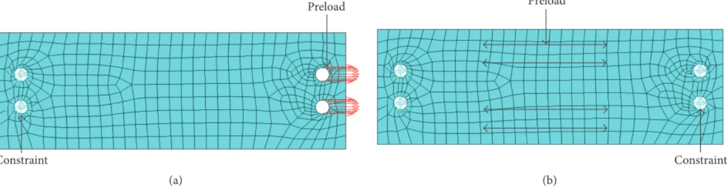
Preload Constraint (a) Preload Constraint (b)
Figure 3: ANSYS simulation model of thin plates. (a) Loading simulation. (b) Dynamics simulation.
(a) 150 50 130 14 4 × Φ6 (b)
Figure 4: (a) Specimen. (b) Size and structure of specimen.
In the simulation, the isotropic thin plate with a preload is replaced with the model whose one side is under displace-ment constraint from all directions and whose other side suffers from certain size pressure representing the size of the preload, as shown in Figure 3(a). After applying the preload, force occurs in the thin-walled plate because of the preload. In dynamics simulation, two sides of the model are under displacement constraints, and the force obtained from the pressure is exerted on the plate, as depicted in Figure 3(b). The holes in the picture are used to fix and load simulation plates. Considering the influence of preload, modal analysis is performed on the basis of this model. We obtain the natural frequency and vibration mode under different preloads.
The finite element simulation analyzes thin plates under different preloads from 0 to 100 N, and 10 N is the increase gradient value of force. Each case analyzes the natural frequencies and vibration modes of the first four orders. The results of simulation are discussed in the following section.
4. Analyses of Experimental and
Simulation Results
The material of thin-walled part used in this experiment is 7075 aluminum alloy. The size and structure of the specimens are shown in Figure 4. The holes are used to fix and load experimental specimens. The material parameters of experimental plates are listed in Table 1.
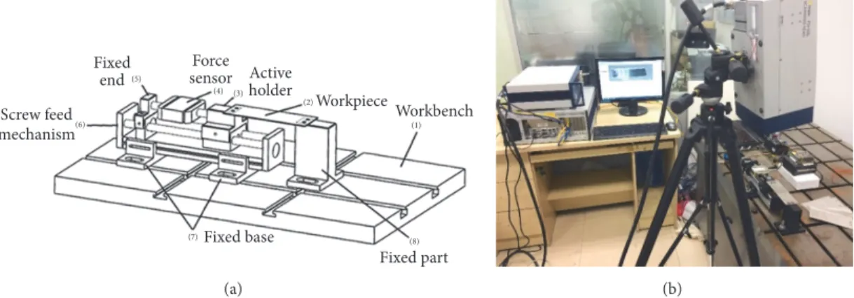
The comprehensive experiment platform is indepen-dently machined and assembled by us. It includes a control
system and a loading system as described in Figure 5(a). The scanning laser vibrometer is used to measure vibration of thin aluminum alloy plates. The experiment platform and vibrometer are shown in Figure 5(b).
The specific experimental steps are as follows:
(1) The experimental apparatus includes experimental
equipment of MCU development, a two-phase hybrid stepper motor drive, a stepper motor, and an intelligent controller. We set the instrument and adjust parameters to ensure that all the instruments function properly and that the control system can effectively control step motor rotation.
(2) A scanning laser vibrometer is installed using the
manual, and a fixed tripod of the laser scanning head is adjusted to position the laser perpendicular to the thin-walled board, as described in Figure 5(b). This step is especially important.
(3)The thin plate is installed and fixed on the
experimen-tal platform, and the initial preload of the plate is 0 N.
(4)Through positive and negative buttons on the MCU
development board, a stepping motor is controlled to exert different sizes of preload for thin-walled parts from 0 to 100 N, and a force of 10 N is added every time.
(5)By exciting the thin plate with an elastic force hammer,
the dynamic characteristic parameters of thin-walled work-pieces are obtained using control and analysis software PSV-500.
(6)Replacing the thin plate, steps(3)to(5)are repeated.
11 groups of data are received. Data contain the natural frequencies of the first four orders in each group.
Workbench Workpiece Active holder Force sensor Fixed end Screw feed mechanism Fixed base Fixed part (1) (8) (7) (6) (5) (4) (3) (2) (a) (b)
Figure 5: (a) Comprehensive experiment platform. (b) Comprehensive test experiment platform and scanning laser vibrometer.
500 Frequency (Hz) 0 0.5 1 1.5 2 200 800 M agni tude (mm/s) First order Second order
Third order Fourth order
Figure 6: Experimental natural frequency of first four orders of thin-walled plates under a 50 N preload.
Table 2: Average error of the natural frequency values of the first four orders from simulation and experiment.
Natural frequency order The first order The second order The third order The fourth order Average error 2.9% 1.9% 0.9% 0.4%
The dynamic characteristic parameters of the thin-walled
part under preload 𝐹 = 50N are measured using a
comprehensive test experiment platform and a scanning laser vibrometer (Figure 6).
The average error of the natural frequency values of the first four orders obtained from the simulation and experiment is expressed in Table 2. All the average error values of natural frequency are small and the largest value is only 2.9%. All of the average error values fall within the acceptable range in engineering.
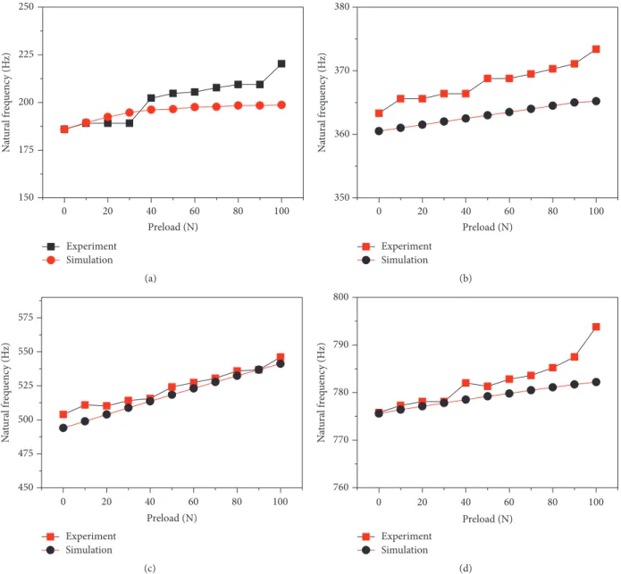
To intuitively show the distinction between the simula-tion and experiment, contrast curves of the first four orders of the simulation and experiment are compared, in Figure 7. Based on the shape of the curves, both the simulation and experiment show that the natural frequencies of thin plates increase following the augmentation of the preload. As described in the curve graphs, the change of the natural frequency from experiments is more apparent than that in simulations; nevertheless, they all increase. The shapes of the
simulation curves are approximately linear and more regular. The experiment curves are relatively discrete, but the curves of the experiment and simulation values are extremely close. When preload is from 0 N to 100 N, the maximal variation of natural frequency is 42.2 Hz at third-order experimental status. All curves indicate that the experiment values are greater than the simulation values. This situation is realistic.
Equation (4) shows influence factors of natural frequency. Boundary conditions can affect the main vibration mode of
thin-walled plate, and change of preload can alter the𝑊(𝑥, 𝑦)
to get different frequencies. However, the mathematical
expression of𝑊(𝑥, 𝑦)almost can not be calculated in detail,
so we interpreted it from another perspective. Assuming that
boundary conditions are invariable, increase of𝐹is equal to
the augment of stiffness for lateral vibration of plate and main vibration mode is fixed. That is to say, it leads to augmentation
of elasticity modulus𝐸. According to𝐷 = 𝐸ℎ3/12(1−𝜇2)and
(4), the increase of𝐹enlarges the natural frequency of
thin-walled plate.
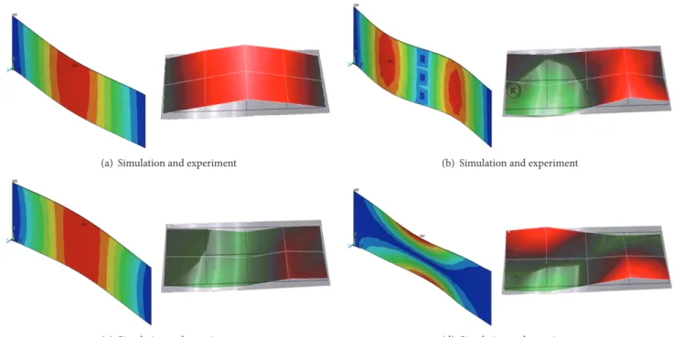
When the plates undergo a preload𝐹 = 50N, the
vibra-tion modes obtained through simulavibra-tion and experiment are similar (Figure 8).
Given the aforementioned simulation and experiment research for thin plates with different preloads, natural frequencies can be estimated by writing a program. The interface is exhibited in Figure 9. The software is used to calculate the natural frequency of the thin-walled plate under different preloads. This is important reference to control the natural frequency to reduce vibration in employing and manufacturing of aerospace thin-walled components. Natural frequency values and vibration mode graphics of the first six orders are provided in the picture.
A easy and practical engineering method controlling vibration is found. Severe vibration occurs when the forcing frequency is equal to natural frequency. The machining process of thin-walled workpieces and the practical applica-tion are influenced by the vibraapplica-tion. Changing the preload varies the stiffness and it causes the natural frequency of the system to change continuously. Resonance frequency of system is changed and vibration of aviation thin-walled parts is reduced via adjusting preload within effective range.
0 20 40 60 80 100 150 175 200 225 250 Preload (N) N at ural f req uenc y (H z) Experiment Simulation (a) 0 20 40 60 80 100 350 360 370 380 Preload (N) N at ural f req uenc y (H z) Experiment Simulation (b) 0 20 40 60 80 100 450 475 500 525 550 575 Preload (N) N at ural f req uenc y (H z) Experiment Simulation (c) 0 20 40 60 80 100 760 770 780 790 800 Preload (N) N at ural f req uenc y (H z) Experiment Simulation (d)
Figure 7: Contrast curves of simulation and experimental values of the natural frequency of the first four orders. (a) First-order natural frequency. (b) Second-order natural frequency. (c) Third-order natural frequency. (d) Fourth-order natural frequency.
5. Conclusions
(1) The finite element simulation analysis of the dynamic
characteristics of thin plates under pretightening force includes a 3D model and modal analysis simulation. Through simulation, the relationship between preload and modal parameters, such as natural frequency and vibration mode, is obtained.
(2)Comprehensive experiment platform used to measure
dynamic characteristics of aviation thin-walled parts under a certain preload is designed, and experimental modal analysis of the parts is carried out. The law that natural frequency increases with increasing preload is summarized based on analysis of the numerical solutions and experimental solu-tions of the dynamic characteristics.
(3)According to the results of simulation and experiment,
resizing preload to change the natural frequency of parts is a highly effective approach to avoid strong vibration of aerospace thin-walled workpieces.
(4)On the basis of the finite element software ANSYS,
computing system of dynamic characteristic parameters of thin-walled components under preload is developed adopt-ing object-oriented development language. This software simplifies treatment processes of finite element analysis, shortens the analysis time, achieves parametric modeling, and improves efficiency.
Conflicts of Interest
(a) Simulation and experiment (b) Simulation and experiment
(c) Simulation and experiment (d) Simulation and experiment
Figure 8: Contrast graphs of simulation and experiment values of the vibration mode of the first four orders. (a) The first-order vibration mode. (b) The second-order vibration mode. (c) The third-order vibration mode. (d) The fourth-order vibration mode.
Figure 9: Screenshot of the program and calculation results.
Authors’ Contributions
Qiong Wu, Lei Li, and Yi-Du Zhang conceived and designed the experiments; Qiong Wu and Lei Li performed the exper-iments; Qiong Wu and Lei Li analyzed the data; Qiong Wu and Lei Li wrote the paper.
Acknowledgments
This work was supported by the National Science and Tech-nology Major Project (Grant no. 2014ZX04001011), Defense
Industrial Technology Development Program (Grant no. A0520110009), and Beijing Municipal Natural Science Foun-dation (Grant no. 3172021).
References
[1] R. Izamshah, J. P. T. Mo, and S. Ding, “Hybrid deflection prediction on machining thin-wall monolithic aerospace com-ponents,”Proceedings of the Institution of Mechanical Engineers, Part B: Journal of Engineering Manufacture, vol. 226, no. 4, pp. 592–605, 2012.
[2] I. Raja, “Deflection prediction on machining thin-walled monolithic aerospace component,”Proceedings of the Institution of Mechanical Engineers, Part B: Journal of Engineering Manu-facture, vol. 226, no. 4, pp. 592–605, 2011.
[3] Q. Wu and D.-P. Li, “Analysis and X-ray measurements of cutting residual stresses in 7075 aluminum alloy in high speed machining,”International Journal of Precision Engineering and Manufacturing, vol. 15, no. 8, pp. 1499–1506, 2014.
[4] Q. Wu, D.-P. Li, and Y.-D. Zhang, “Detecting milling deforma-tion in 7075 aluminum alloy aeronautical monolithic compo-nents using the quasi-symmetric machining method,”Metals, vol. 6, no. 4, article no. 80, 2016.
[5] K. P. S. Rana, “Fuzzy control of an electrodynamic shaker for automotive and aerospace vibration testing,”Expert Systems with Applications, vol. 38, no. 9, pp. 11335–11346, 2011.
[6] M. Aykan and M. C¸ elik, “Vibration fatigue analysis and multi-axial effect in testing of aerospace structures,” Mechanical Systems and Signal Processing, vol. 23, no. 3, pp. 897–907, 2009. [7] Y.-S. Shih and G.-Y. Wu, “Effect of vibration on fatigue crack
growth of an edge crack for a rectangular plate,”International Journal of Fatigue, vol. 24, no. 5, pp. 557–566, 2002.
[8] P. Wang, H. Ni, R. Wang, Z. Li, and Y. Wang, “Experimental investigation of the effect of in-plane vibrations on friction for different materials,”Tribology International, vol. 99, pp. 237–247, 2016.
[9] J. Muric-Nesic, P. Compston, N. Noble, and Z. H. Stachurski, “Effect of low frequency vibrations on void content in composite materials,”Composites Part A: Applied Science and Manufactur-ing, vol. 40, no. 4, pp. 548–551, 2009.
[10] S. Biswas, S. Habib Alavi, and S. P. Harimkar, “Laser surface melting of Ti-6Al-4V under the influence of ultrasonic vibra-tions,”Materials Letters, vol. 159, Article ID 19257, pp. 470–473, 2015.
[11] Z. Yao, G.-Y. Kim, L. Faidley, Q. Zou, D. Mei, and Z. Chen, “Effects of superimposed high-frequency vibration on defor-mation of aluminum in micro/meso-scale upsetting,”Journal of Materials Processing Technology, vol. 212, no. 3, pp. 640–646, 2012.
[12] Y. Ishida, “Recent development of the passive vibration control method,”Mechanical Systems and Signal Processing, vol. 29, pp. 2–18, 2012.
[13] T. P. Sales, D. A. Rade, and L. C. G. de Souza, “Passive vibra-tion control of flexible spacecraft using shunted piezoelectric transducers,”Aerospace Science and Technology, vol. 29, no. 1, pp. 403–412, 2013.
[14] Y. Zhang, Y. Zang, M. Li, Y. Wang, and W. Li, “Active-passive integrated vibration control for control moment gyros and its application to satellites,”Journal of Sound and Vibration, vol. 394, pp. 1–14, 2017.
[15] J. S. Yang, “Hybrid active and passive control of a very large floating beam structure,”Nonlinear Dynamics, vol. 87, no. 3, pp. 1835–1845, 2017.
[16] D. Gong, J. Zhou, and W. Sun, “Passive control of railway vehicle car body flexural vibration by means of underframe dampers,”
Journal of Mechanical Science and Technology, vol. 31, no. 2, pp. 555–564, 2017.
[17] A. Preumont, “Vibration Control of Active Structures: An Introduction,”Meccanica, vol. 179, no. 2, p. 139, 1999.
[18] J. Plattenburg, J. T. Dreyer, and R. Singh, “Vibration control of a cylindrical shell with concurrent active piezoelectric patches and passive cardboard liner,”Mechanical Systems and Signal Processing, vol. 91, pp. 422–437, 2017.
[19] T. Bailey and J. E. Ubbard, “Distributed piezoelectric-polymer active vibration control of a cantilever beam,”Journal of Guid-ance, Control, and Dynamics, vol. 8, no. 5, pp. 605–611, 1985. [20] A. Shimamoto and N. Kurosawa, “Active vibration control for
truss bridge model by shrinkage force in shape memory alloy wire,”Science, vol. 309, no. 5739, pp. 1338–1343, 2005.
[21] A. Baz, K. Imam, and J. McCoy, “Active vibration control of flexible beams using shape memory actuators,”Journal of Sound and Vibration, vol. 140, no. 3, pp. 437–456, 1990.
[22] E. Omidi, S. N. Mahmoodi, and W. S. Shepard, “Vibration reduction in aerospace structures via an optimized modified positive velocity feedback control,”Aerospace Science and Tech-nology, vol. 45, article no. 3350, pp. 408–415, 2015.
[23] H. Y. Lin and C. Y. Wang, “Free vibration analysis of a hybrid beam composed of multiple elastic beam segments and elastic-supported rigid bodies,”Journal of Marine Science and Technology, vol. 20, no. 5, pp. 525–533, 2012.
[24] H.-Y. Lin, “On the natural frequencies and mode shapes of a multi-span and multi-step beam carrying a number of concentrated elements,”Structural Engineering and Mechanics, vol. 29, no. 5, pp. 531–550, 2008.
[25] H.-Y. Lin, “An exact solution for free vibrations of a non-uniform beam carrying multiple elastic-supported rigid bars,”
Structural Engineering and Mechanics, vol. 34, no. 4, pp. 399– 416, 2010.
[26] H. L. Dai, D. M. Zhao, J. J. Zou, and L. Wang, “Surface effect on the nonlinear forced vibration of cantilevered nanobeams,”
Physica E: Low-dimensional Systems and Nanostructures, vol. 80, pp. 25–30, 2016.
[27] S. H. Diaz Valdes and C. Soutis, “Delamination detection in composite laminates from variations of their modal character-istics,”Journal of Sound and Vibration, vol. 228, no. 1, pp. 1–9, 1999.
[28] N. Ashwear and A. Eriksson, “Natural frequencies describe the pre-stress in tensegrity structures,”Computers & Structures, vol. 138, pp. 162–171, 2014.
[29] N. Vlajic, T. Fitzgerald, V. Nguyen, and B. Balachandran, “Geometrically exact planar beams with initial pre-stress and large curvature: Static configurations, natural frequencies, and mode shapes,”International Journal of Solids and Structures, vol. 51, no. 19-20, pp. 3361–3371, 2014.
[30] M. Rabenda and B. Michalak, “Natural vibrations of prestressed thin functionally graded plates with dense system of ribs in two directions,”Composite Structures, vol. 133, pp. 1016–1023, 2015. [31] T. Murmu and S. C. Pradhan, “Small-scale effect on the
vibration of nonuniform nanocantilever based on nonlocal elasticity theory,” Physica E: Low-dimensional Systems and Nanostructures, vol. 41, no. 8, pp. 1451–1456, 2009.
[32] T. Murmu and S. C. Pradhan, “Vibration analysis of nanoplates under uniaxial prestressed conditions via nonlocal elasticity,”
Journal of Applied Physics, vol. 106, no. 10, Article ID 104301, 2009.
[33] B. U˘gurlu, “A dual reciprocity boundary element solution method for the free vibration analysis of fluid-coupled Kirch-hoff plates,”Journal of Sound and Vibration, vol. 340, pp. 190– 210, 2015.
,QWHUQDWLRQDO-RXUQDORI
$HURVSDFH
(QJLQHHULQJ
+LQGDZL3XEOLVKLQJ&RUSRUDWLRQ KWWSZZZKLQGDZLFRP 9ROXPHRobotics
Journal ofHindawi Publishing Corporation
http://www.hindawi.com Volume 2014
Hindawi Publishing Corporation
http://www.hindawi.com Volume 2014
Active and Passive Electronic Components
Control Science and Engineering
Journal of
Hindawi Publishing Corporation
http://www.hindawi.com Volume 2014
Machinery
Hindawi Publishing Corporation
http://www.hindawi.com Volume 2014 Hindawi Publishing Corporation
http://www.hindawi.com
Journal of
(QJLQHHULQJ
Volume 201Submit your manuscripts at
https://www.hindawi.com
VLSI Design
Hindawi Publishing Corporation
http://www.hindawi.com Volume 201
-Hindawi Publishing Corporation
http://www.hindawi.com Volume 2014 Shock and Vibration
Hindawi Publishing Corporation
http://www.hindawi.com Volume 2014
Civil Engineering
Advances inAcoustics and VibrationAdvances in
Hindawi Publishing Corporation
http://www.hindawi.com Volume 2014
Hindawi Publishing Corporation
http://www.hindawi.com Volume 2014 Electrical and Computer Engineering
Journal of
Advances in OptoElectronics
Hindawi Publishing Corporation
http://www.hindawi.com Volume 2014
The Scientific
World Journal
Hindawi Publishing Corporation
http://www.hindawi.com Volume 2014
Sensors
Journal ofHindawi Publishing Corporation
http://www.hindawi.com Volume 2014
Modelling & Simulation in Engineering
Hindawi Publishing Corporation
http://www.hindawi.com Volume 2014
Hindawi Publishing Corporation
http://www.hindawi.com Volume 2014
Chemical Engineering
International Journal of Antennas and
Propagation
International Journal of
Hindawi Publishing Corporation
http://www.hindawi.com Volume 2014
Hindawi Publishing Corporation
http://www.hindawi.com Volume 2014
Navigation and Observation
International Journal of
Hindawi Publishing Corporation
http://www.hindawi.com Volume 2014