Interface (M8/16EABI)
SYSTEM V APPLICATION BINARY INTERFACE
Motorola M68HC05, M68HC08, M68HC11, M68HC12, and M68HC16 Processors
Supplement
Copyright 1991,1992 88open Consortium Ltd.. All rights reserved.
This specification includes material copyrighted by 88open Consortium Ltd., which is reproduced with permission.
This specification includes material copyrighted by The Santa Cruz Operation, Inc. which is reproduced with permission.
Important Notice to Users
Every effort has been made to ensure the accuracy of all information in this document. Motorola assumes no liability to any party for any loss or damage caused by errors or omissions or by statements of any kind in this document, its updates, supplements, or special editions, whether such errors are omissions or statements resulting from negligence, accident, or any other cause. Motorola further assumes no liability arising out of the application or use of any information, product, or system described herein; nor any liability for incidental or consequential damages arising from the use of this document. Motorola disclaims all warranties regarding the information contained herein, whether expressed, implied or statutory, including implied warranties of merchantability or fitness for a particular purpose. Motorola makes no representation that the interconnection of products in the manner described herein will not infringe on existing or future patent rights, nor do the descriptions contained herein imply the granting or license to make, use, or sell equipment constructed in accordance with this description.
Trademarks
Motorola is a trademark of Motorola, Inc.
The Santa Cruz Operation is a registered trademark of The Santa Cruz Operation, Inc. in the USA and other countries.
References
System V Application Binary Interface, Fourth Edition, UNIX System Laboratories, 1995. System V Application Binary Interface, Motorola 88000 Processor Supplement, 88open Consortium Ltd., 1992.
DWARF Debugging Information Format, Revision 2.0.0, Industry Review Draft, UNIX International, Programming Languages SIG, July 27, 1993.
The M68HC05 Applications Guide, M68HC05AG/AD 3.0, Motorola The CPU08 Reference Manual, CPU08RM/AD 2.0, Motorola The M68HC11 Reference Manual, M68HC11RM/D 3.0, Motorola The HC12 CPU12 Reference Manual, CPU12RM/AD 1.0, Motorola The CPU16 Reference Manual, CPU16RM/AD 1.0, Motorola
1. INTRODUCTION ...1
THE MOTOROLA 8- AND 16-BIT PROCESSORS AND THE SYSTEM V ABI...1
HOW TO USE THE M8/16EABI...1
EVOLUTION OF THE EABI SPECIFICATION...1
2. SOFTWARE INSTALLATION ...2
3. LOW-LEVEL SYSTEM INFORMATION...3
SYSTEM V ABI EXECUTION SUPPORT...3
MACHINE INTERFACE...3
Processor Architecture ...3
Data Representation ...3
FUNCTION CALLING SEQUENCE...5
OPERATING SYSTEM INTERFACE...5
4. OBJECT FILES...6
INTRODUCTION...6
DATA REPRESENTATION...6
ELF HEADER...7
Machine Information ...7
SECTIONS...8
Special Sections ...8
Relocation...9
5. PROGRAM LOADING AND DYNAMIC LINKING ...10
PROGRAM LOADING...10
DYNAMIC LINKING...10
6. LIBRARIES ...11
7. DWARF DEBUGGING INFORMATION FORMAT ...12
DWARF DEFINITION...12
DWARF Register Number Mapping ...12
Target-Specific Addressing Information...13
Calling Convention Encodings ...15
Target Machine Address Size ...16
8. S-RECORDS ...17
1. INTRODUCTION
The Motorola 8- and 16-Bit Processors and the System V ABI
The System V Application Binary Interface, or System V ABI, defines a system interface for compiled application programs. Its purpose is to establish a standard binary interface for application programs on systems that implement the operating system interfaces defined in the System V Interface Definition, Fourth Edition.
The Motorola 8- and 16-Bit Embedded Application Binary Interface (which will be referred to as the EABI), described in this document, supplements the generic System V ABI, and it contains information specific to an implementation on the Motorola M68HC05, M68HC08, M68HC11, M68HC12, M68HC16 processor architectures. Together, these two specifications, the generic System V ABI and the EABI, constitute a complete System V Application Binary Interface for systems that implement the architecture of these processors.
The issues addressed in the EABI are considerably narrower in scope than the generic System V ABI. The EABI was created to meet the unique needs of M68HC05, M68HC08, M68HC11, M68HC12, and M68HC16 embedded applications and tools, and does not discuss the many high-level operating system interfaces addressed in the generic System V ABI. The focus is primarily on the low-level system information and object files (ELF file format).
The EABI specifies DWARF 2.0 as the debugging information format. This format is described in DWARF Debugging Information Format, Revision 2.0.0.
Version 2.0 of the EABI defines a set of conventions for linked executable files. The goal is to define a standard that permits a file produced by one vendor’s linker to be consumed by another vendor’s debugger, programmer, etc.
How to Use the M8/16EABI
While the generic System V ABI is the prime reference document, the EABI contains M68HC05, M68HC08, M68HC11, M68HC12, and M68HC16 processor-specific implementation details, some of which supersede information in the generic one.
As with the System V ABI, this document refers to other publicly available reference documents (e.g. CPU12 Reference Manual, DWARF Debugging Information Format Revision 2.0.0). All the information referenced by the EABI should be considered part of the EABI, and just as binding as the requirements and data it explicitly includes.
Evolution of the EABI Specification
Characteristics and behaviors mandated by this version of the EABI shall continue to be
mandated indefinitely except where this document explicitly states otherwise. All mandates that might be withdrawn or altered in the next edition of the EABI are clearly identified by the NOTE identifier:
2. SOFTWARE INSTALLATION
Unlike the System V ABI, the EABI shall not have required physical media for distribution of EABI-conforming application software; a required software format (such as a continuous data stream) on the physical media; a required layout of files on the physical media; or a required format or interpretation of installation data files.
3. LOW-LEVEL SYSTEM INFORMATION
System V ABI Execution Support
An EABI-conforming entity, such as an application or a static linker, shall not have requirements pertaining to:
• dynamic linking • global offset tables • procedure linkage tables • shared objects
Machine Interface
Processor Architecture
The appropriate CPUxx reference manual defines the M68HC05, M68HC08, M68HC11, M68HC12, or M68HC16 architectures. Programs intended to execute directly on the processor use the appropriate instruction set, and the instruction encodings and semantics of the respective architecture.
An application program may assume that all instructions defined by the architecture exist and work as documented.
To be EABI-conforming, the processor must implement the instructions of the architecture, perform the specified operations, and produce the expected results. The EABI neither places performance on systems nor specifies what instructions must be implemented in hardware. A software emulation of the architecture could conform to the EABI.
Data Representation
Byte Ordering
Byte ordering defines how the bytes that make up 16-bit and 32-bit values are ordered in memory. The CPU05, 08, 11, 12, 16 supports significant byte (MSB) ordering, or “Big-Endian” as it is sometimes called, meaning that the most significant byte is located in the lowest addressed byte position in a storage unit.
Fundamental Types
An entity conforming to Version 2.0 of the EABI shall not have requirements pertaining to the size or alignment of fundamental types (e.g., char, short, int, long, float, double). A 4-byte floating-point number shall conform to the single-precision format of the IEEE-754 floating-point specification.
An 8-byte floating-point number shall conform to the double-precision format of the IEEE-754 floating-point specification.
Aggregates and Unions
An entity conforming to Version 2.0 of the EABI shall not have requirements pertaining to the alignment or padding of aggregates (structures and arrays) and unions.
Bit-Fields
An entity conforming to Version 2.0 of the EABI shall not have requirements pertaining to the width and ranges of the integral objects defined by “bit-fields” in C struct and union definitions. Version 2.0 of the EABI does not define whether a “plain” bit-field is signed or unsigned.
NOTE
NOTE
NOTE
Future versions of the EABI may define requirements for the size and alignment of fundamental types.
Future versions of the EABI may define requirements pertaining to the alignment or padding of aggregates and unions.
Future versions of the EABI may define requirements for the width and range of bit-fields.
Function Calling Sequence
An entity conforming to Version 2.0 of the EABI shall not have requirements pertaining to: • calling conventions
• register usage during a function calling sequence • the stack frame
• parameter passing • variable argument lists • return values
Operating System Interface
Unlike the System V ABI, an EABI-conforming entity shall not have operating system interface requirements.
NOTE
Future versions of the EABI may define requirements pertaining to calling conventions, register usage during a function calling sequence, the stack frame, parameter passing, variable argument lists, and return values.
4. OBJECT FILES
Introduction
This section describes the object file format, called ELF (Executable and Linking Format).
Data Representation
Certain members of the M68HC11, M68HC12, and M68HC16 families incorporate support for addressing a larger memory space than the standard 64-Kb through a paged memory or bank-switching scheme.
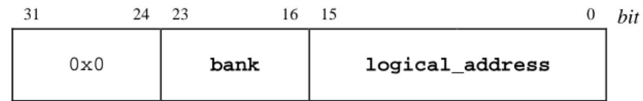
The EABI defines the System V ABI Elf32_Addr data type as having the following format in order to support banking:
31 24 23 16 15 0 bit
0x0 bank logical_address
bank For logical addresses falling within a bank window, this is the value of
the page register. For addresses that do not fall in a bank window, this value is 0x0. For devices that do not support banked addressing, this value is 0x0.
logical_address This is the address within the 64-Kb address space of the M68HC11,
M68HC12, or M68HC16. For banked addresses, the value of
logical_address determines which page register (PPAGE, DPAGE, or EPAGE) the bank value belongs in. For memory expansion
information for a particular divice in the family above, please refer to the technical specification for that device.
Figure 4-1, Example of Elf32_Addr format
The CPU12 Reference Manual documents that the program window (controlled by the PPAGE register) always occupies the 16-Kb space from 0x8000 to 0xBFFF. Suppose an Elf32_Addr address had the value 0x00129000. Its meaning is as follows:
The value of logical_address is 0x9000. This specifies the address within the 64-Kb address space of the M68HC12. Since 0x9000 falls within the program window this identifies that the value of bank belongs in the PPAGE register.
The value of bank is 0x12. This value belongs in the PPAGE register. NOTE
The System V ABI describes three main types of object files—relocatable,
executable, and shared object. Version 2.0 of the EABI requires that conforming entities support executable files. The other types of object files may be addressed in a future version of the EABI.
ELF Header
Machine Information
For file identification in e_ident, the EABI requires the values shown in Figure 4-2.
Figure 4-2, M68HC05, M68HC08, M68HC11, M68HC12, and M68HC16 Identification, e_ident
Position Value Comments
e_ident[EI_CLASS] 1 (ELFCLASS32) Address space < 4 Gbytes
e_ident[EI_DATA] 2 (ELFDATA2MSB) M8/16 Processors are Big-Endian e_ident[EI_VERSION] 1 Original ELF file format
Please note that the ELFDATA2MSB value specifies that data objects in a file are encoded as 2’s complement values, with the most significant byte occupying the lowest address (Big-Endian). For the object type member e_type, an entity conforming to Version 2.0 of the EABI must support the type ET_EXEC, which specifies an executable file.
Processor identification resides in the ELF header’s e_machine member and must have the following values:
Decimal 72 - defined as the name EM_68HC05, Decimal 71 - defined as the name EM_68HC08, Decimal 70 - defined as the name EM_68HC11, Decimal 53 - defined as the name EM_68HC12, Decimal 69 - defined as the name EM_68HC16.
NOTE
A draft of an ELF specification has been circulated among some tools developers with an unofficial value specified for e_machine. The value specified for the M68HC12 processor was 0x4D12. While an object file with this value would not conform to the EABI, a consuming tool developer may wish to recognize it.
Sections
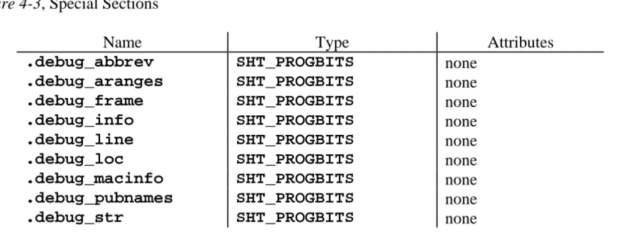
Special Sections
In addition to the special sections defined in the generic System V ABI, the EABI defines the sections in the list below.
Figure 4-3, Special Sections
Name Type Attributes
.debug_abbrev SHT_PROGBITS none
.debug_aranges SHT_PROGBITS none
.debug_frame SHT_PROGBITS none
.debug_info SHT_PROGBITS none
.debug_line SHT_PROGBITS none
.debug_loc SHT_PROGBITS none
.debug_macinfo SHT_PROGBITS none
.debug_pubnames SHT_PROGBITS none
.debug_str SHT_PROGBITS none
.debug_abbrev This section holds DWARF 2.0 abbreviation tables.
.debug_aranges This section holds the DWARF 2.0 lookup table to find the debugging information for an object by address.
.debug_frame This section holds DWARF 2.0 virtual unwind information. .debug_info This section holds DWARF 2.0 debugging information entries. .debug_line This section holds DWARF 2.0 line number information. .debug_loc This section holds DWARF 2.0 location lists.
.debug_macinfo This section holds DWARF 2.0 macro information.
.debug_pubnames This section holds the DWARF 2.0 lookup table to find the debugging information for an object by name.
.debug_str This section holds string values for DWARF 2.0 attributes. NOTE
While a section header table is not required in a linked executable file, the table and the accompanying section name string table (.shstrtab section) are necessary for a debugger to locate the sections specifying debugging information.
Relocation
An entity conforming to Version 2.0 of the EABI shall not have requirements pertaining to relocation.
NOTE
5. PROGRAM LOADING AND DYNAMIC LINKING
Program Loading
An EABI-conforming entity shall not have program loading requirements.
Dynamic Linking
6. LIBRARIES
An entity conforming to Version 2.0 of the EABI shall not have requirements pertaining to library interfaces.
NOTE
7.
DWARF Debugging Information Format
DWARF Definition
The EABI adopts DWARF Version 2.0 as the debugging format for EABI-conforming applications. This format is described in DWARF Debugging Information Format, Revision 2.0.0.
DWARF is a specification developed for symbolic, source-level debugging. The debugging information format does not favor the design of any compiler or debugger.
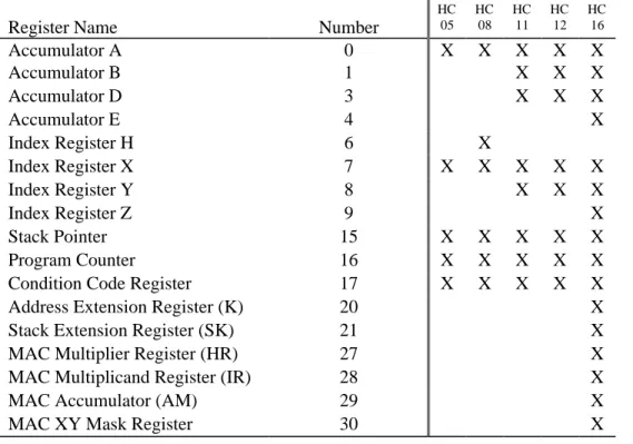
DWARF Register Number Mapping
Figure 7-1 outlines the register number mapping for the M68HC05, M68HC08, M68HC11, M68HC12, and M68HC16 processor families. See Section 2.4.2 of DWARF Debugging Information Format, Revision 2.0.0 for additional information regarding register-naming operations.
Figure 7-1, Motorola 8/16-Bit Processor Register Number Mapping
Register Name Number
HC 05 HC 08 HC 11 HC 12 HC 16
Accumulator A 0 X X X X X
Accumulator B 1 X X X
Accumulator D 3 X X X
Accumulator E 4 X
Index Register H 6 X
Index Register X 7 X X X X X
Index Register Y 8 X X X
Index Register Z 9 X
Stack Pointer 15 X X X X X
Program Counter 16 X X X X X
Condition Code Register 17 X X X X X
Address Extension Register (K) 20 X
Stack Extension Register (SK) 21 X
MAC Multiplier Register (HR) 27 X
MAC Multiplicand Register (IR) 28 X
MAC Accumulator (AM) 29 X
Target-Specific Addressing Information
Any debugging information entry representing a pointer or reference type or a subroutine or subroutine type may have a DW_AT_address_class attribute, whose value is a constant. The set of permissible values for the M68HC12 processor family is described in Figure 7-2. Figure 7-2, Address Class Codes
Code Value Meaning
DW_ADDR_none 0 No class specified DW_ADDR_page_2 1 Page value is in byte 2
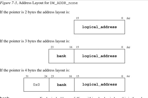
If the DW_AT_address_class attribute is not present or has a value of DW_ADDR_none, the address has the format described below in Figure 7-3.
Figure 7-3, Address Layout for DW_ADDR_none If the pointer is 2 bytes the address layout is:
15 0 bit
logical_address
If the pointer is 3 bytes the address layout is:
23 16 15 0 bit
bank logical_address
If the pointer is 4 bytes the address layout is:
31 24 23 16 15 0 bit
0x0 bank logical_address
bank For logical addresses falling within a bank window, this is the value of the page register. For addresses that do not fall in a bank window, this value is 0x0. For devices in the Motorola 8- and 16-bit families that do not support banked addressing, this value is 0x0.
logical_address This is the address within the 64-Kb address space of the M68HC11, M68HC12, and M68HC16. For banked addresses, the value of logical_address determines which page register (PPAGE, DPAGE, or EPAGE) the bank value belongs in. For memory expansion information for a particular device in the these families, please refer to the technical specification for that device.
If the DW_AT_address_class attribute is present and has a value of DW_ADDR_page_2, the address has the format described below in Figure 7-4.
Figure 7-4, Address Layout for DW_ADDR_page_2 If the pointer is 3 bytes the address layout is:
23 8 7 0 bit
logical_address bank
If the pointer is 4 bytes the address layout is:
31 24 23 8 7 0 bit
0x0 logical_address bank
bank For logical addresses falling within a bank window, this is the value of the page register. For addresses that do not fall in a bank window, this value is 0x0. For devices in the Motorola 8- and 16-bit families that do not support banked addressing, this value is 0x0.
logical_address This is the address within the 64-Kb address space of the M68HC11, M68HC12, and M68HC16. For banked addresses, the value of logical_address determines which page register (PPAGE, DPAGE, or EPAGE) the bank value belongs in. For memory expansion information for a particular device in these families, please refer to the technical specification for that device.
Calling Convention Encodings
Certain members of the M68HC11, M68HC12, and M68HC16 families incorporate support for addressing a larger memory space than the standard 64-Kb through a paged memory or bank-switching scheme. Functions can reside in this expanded memory. The EABI specifies that the DWARF DW_AT_calling_convention attribute should be used to distinguish the different ways in which a function may be called. This attribute provides the debugger the necessary information to perform a back trace using the stack.
The encodings for values of the DW_AT_calling_convention attribute are given in figure 7-5.
Figure 7-5, Calling Convention Encodings
Code Value
DW_CC_normal 0x1
DW_CC_nocall 0x3
DW_CC_far 0x40
The DW_CC_far value shall be used to identify a banked function (called with the CALL instruction).
The DW_CC_nocall value shall be used to identify an interrupt handler function (terminated by RTI instruction).
If the DW_AT_calling_convention attribute is not present or has a value of
DW_CC_normal, the function shall be assumed to be non-banked (called with the JSR or BSR instructions).
Target Machine Address Size
The DWARF Debugging Information Format, Revision 2.0.0 specification makes numerous references to “the size of an address on the target machine.” While the M68HC11, M68HC12, and M68HC16 architectures define a 16-bit logical address space, in order to support banked addressing, the EABI defines DWARF “target machine addresses” to be 4 bytes (32 bits) with the following format:
31 24 23 16 15 0 bit
0x0 bank logical_address
bank For logical addresses falling within a bank window, this is the value of the page register. For addresses that do not fall in a bank window, this value is 0x0. For devices in the Motorola 8- and 16-bit families that do not support banked addressing, this value is 0x0.
logical_address This is the address within the 64-Kb address space of the M68HC11, M68HC12, and M68HC16. For banked addresses, the value of logical_address determines which page register (PPAGE, DPAGE, or EPAGE) the bank value belongs in. For memory expansion information for a particular device in these families, please refer to the technical specification for that chip.
Thus, the value of a DWARF attribute with the form class “address” (DW_FORM_addr) is 32 bits in size and has the format described above. This also means that a DWARF 2.0 location expression resolves into a 32-bit address in the above format and the size of the location expression stack is 32 bits.
8. S-Records
S-Record Address Format
The Motorola S-Record format encodes programs or data files in a printable format for transportation between computer systems.
For code/ data in banked memory areas (addresses > 2 bytes), the address field of an S-Record for that code/ data shall be encoded with the physical address. The physical address is the value resulting from the expansion by the M68HC11, M68HC12, or M68HC16 of the logical address and the page register value. Memory expansion for a particular device in these families is described in the technical reference for that respective device.