TECHNICAL UNIVERSITY OF CLUJ-NAPOCA
ACTA TECHNICA NAPOCENSIS
Series: Applied Mathematics, Mechanics, and Engineering Vol. 61, Issue IV, November, 2018
PROCESSING PRECISION ON TURNING MACHINE WITH INCLINED
BED FRAME
Dan Ovidiu GLAVAN, Theoharis BABANATSAS, Cornel CIUPAN, Roxana Mihaela BABANATIS-MERCE, Ioan RADU, Marcelo Calvete GASPAR
Abstract: Massive structures with low displacement are not anymore option of choice for modern and precise cutting tool machines. Our team is researching to define new types of structures with two main qualities: controlled deformations easy to predict and therefore to correct with the clear purpose to get the „ideal” product and right materials and way of manufacturing the structure itself in order to obtain lower vibration levels. The paper analyses welded and molded structures, in this case referring to previous papers in dynamics conditions, willing to determine advantages and disadvantages of using them for frames in projecting, producing and exploitation of tool machinery. Experiments following two different principles were done and their results are briefly presented in this paper in order to sustain our theory.
Key words: Lathe, inclined bed frame, precision, load, displacements, welded, molded.
1. INTRODUCTION
The main goal of any project in cutting tool machines area is to design a machine including the manufacturing materials for its part and the procedure of assembling all in the way that the final result fulfil not any local constrain but the principle of obtaining the perfect cutting piece that of course is just an ideal, practically to obtain dimensions and quality of surfaces as close as possible to the requested one with minimum effort. The classic idea about increasing the rigidity of the structure with the purpose to obtain higher precision in the process of manufacturing is to over dimension the structure and obtain minimum deformations. Having harder structures has as a consequence the increase of the quantity of the material used to build the structure, increase of total weight and significantly higher costs. In the modern industrial era this point of view is not accepted anymore especially due to the great achievements that the computer zone and artificial intelligence have suffered[1], [2]. The research presented in this paper refers to the case of a lathe with inclined bedframe, the inclined bedframe having multiple advantages
such as: smaller horizontal area occupied in the production shop, better rigidity of the structure compared with the classic horizontal one, easier evacuation on metal chips resulted in the cutting process but also some disadvantages, the main one to be mentioned is the bigger volume of the bedframe that conducts at the idea of larger material consumption, disadvantage that can be very easy cancel by optimization of internal structure of the bedframe ( ribs, reinforcements, all of them with right position, angles and thickness of material) [3].
Our proposal is takes in consideration that is not inconvenient the fact the bedframe is changing itself as dimension and basic shape with the restriction that the information about the behavior of the structure comes to us in real time and allows corrective actions in idea to compensate the displacements of the structure giving as final result the desired precision of manufacturing.
1.1 The problem
Achieving the maximum precision in manufacturing means achieving almost zero errors in dimensions and shape and it is strictly related to the fact that almost a constraint in high-tech evolutions, that the computer of the machine has to get in real time the information about the values of the displacement in the cross section of the structure when the cutting tool is acting. In theory the things are looking to be to be easy and very clear, but when we are trying to transfer the theory in tool machinery practical engineering, having to deal with complex or irregular shapes and irregular section, all combined with high complexity of the structure and different solutions for bedframe material (iron or steel) welded or moulded to obtain accurate results for the deformations becomes a serious problem and complicated steps and procedure to follow [4], [5].
What is the true value of deformation in the cross section of the bedframe where the cutting tool is acting, how stable is this value in time, how is the attenuation function of the vibrations acting and how can be all these values calculated is our main issue that we are trying to offer an answer for. Solving the problem is not possible using material resistance classic methods, so we need to make use of innovative thinking with multiple non-determined variables put all together in one system of equations that can reply mathematically the real process [6].
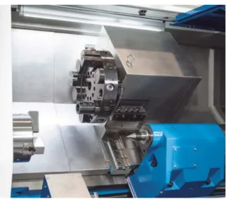
An example of a turning machine with inclined bedframe is exemplified in figure 1.
2. EXPERIMENTAL WORK
The experimental work was done in dynamic conditions with the machine in the manufacturing process and took in consideration two principal directions:
Case A: Study of manufacturing precision using Digital Vibration Meter 3 axis sensor mounted in the cross section where the cutting tool is acting.
Fig. 1: Turning machine with inclined bed frame
Case B: Study of manufacturing precision using the principle of studying and interpreting the direct result of manufacturing on the surface of manufactured piece in very clear conditions for the parameters of the process.
In both cases, in order to simulate the worst possibility when the thickness of the removed material suddenly changes, we used as half-finished materials pieces already processed with constant and controlled quality of surface, the almost instant variation in cutting depth being simulated by a ”hammer” hitting the bedframe of the machine in the cross section where manufacturing took place, several tests (attempts) being done to establish the right mass and start position for the vibration excitation generator[2], [7], [8].
In case A the results were measured directly by the Digital Vibration Meter 3 axis sensor. The tests were relatively simple to interpret, the whole process can be described as a succession of manufacturing in constant conditions (parameters), disruption of the process by the action of the ”hammer”, measurement of consequences by the Digital Vibration Meter 3 axis sensor.
In case B the results were measured scientifically speaking undirect by measuring the roughness on the manufactured piece but engineering speaking those results were the direct consequence of the disturbing action.
correct and we determined a medium value of 2.2 at a cutting speed of 2.000 m/min corresponding to a test piece with diameter of 100 mm, feed mm and revolution speed of turns/min, [7], [9], [10].
On lathes with cast and welded frame, operating conditions measurements were made on several fronts structure frameworks in figure 2 in the following conditions, [2], [7].
● Inclined lathe with cast frame fixed
foundation; Inclined lathe with welded frame fixed foundation;
● Inclined lathe with cast frame fixed to the
main shaft foundation and having unbalanced mass; Parallel lathe with welded frame fixed to the main shaft foundation and having unbalanced mass;
● Inclined lathe with frame cast fixed to the
rubber media.
● Inclined lathe with welded frame fixed to
the rubber mat.
● Inclined lathe with frame cast rubber fixed
on the main shaft and having unbalanced mass.
● Inclined lathe with welded frame fixed on
rubber and having the main shaft unbalanced mass.
For each of the test conditions were made measurements of vibration on the structure frameworks both in the front and in the back. The measurements were carried out in the horizontal direction on the guides and to the base of the frameworks and on the guides in the vertical direction. Measurements were performed passing lathe through the entire speed range from minimum speed to maximum speed both under normal idle running, and if you mounted to the main shaft of the lathe stand a mass unbalanced that would simulate a piece eccentric.
The means of measurement are:
● Digital Vibration Meter 3 axis sensor ● The profile of manufactured piece on a
length of 100 mm compared with a profilometer projector
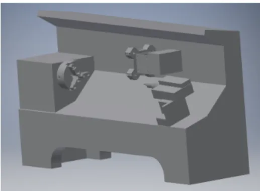
A 3D model of inclined bed was created in order to simulate on computer the same process that we have experimented. [7], [10], [11].
Fig. 2: The model of the inclined lathe
3. 3 RESULTS AND DISCUSSIONS
The mathematical model of inclined bedframe lathe was processed with finite element method software, the outcoming information being used to better interpretation of the experimental work (in fact it was a ¬calibration¬ of our theory)
This part is shown in figure 3 where we can distinguish between the discretization of the structure, the loads and the stress generated in manufacturing process [12].
Fig. 3: The mathematical model charged with stress
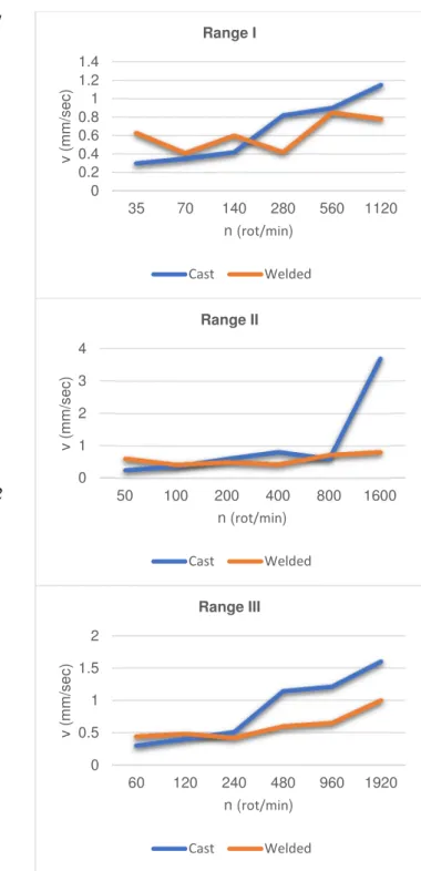
In the first part of our experimental work we measured the vibrations of the structures in manufacturing process, vibrations measured with the 3D sensor, after acting on the structure from outside with the “hammer”, action considered a perturbative force.
Table 1
Cast structure.
n(rot/min) v(mm/s)
Range I
35 0.3 70 0.35 140 0.42 280 0.82 560 0.9 1120 1.15
Range II
50 0.25 100 0.37 200 0.6 400 0.81 800 0.6 1600 3.7
Range III
60 0.3 120 0.4 240 0.51 480 1.14 960 1.21 1920 1.6
Table 2
Welded structure.
n(rot/min) v(mm/s)
Range I
35 0.63 70 0.41 140 0.6 280 0.42 560 0.85 1120 0.78
Range II
50 0.61 100 0.42 200 0.5 400 0.43 800 0.72 1600 0.81
Range III
60 0.44 120 0.48 240 0.42 480 0.6 960 0.65 1920 1
The corresponding results are represented in the diagrams, figure 4.
Fig. 4. Comparative diagrams for casted and welded bed frame structures for range I, II and III
The second part of the experimental work consisted in comparing the profile of the manufactured piece on a length of 100 mm, the differences on two studied cases were determined with a optic profilometer, the results are shown in Figure 5.
0 0.2 0.4 0.6 0.8 1 1.2 1.4
35 70 140 280 560 1120
v
(
m
m
/s
e
c
)
n (rot/min)
Range I
Cast Welded
0 1 2 3 4
50 100 200 400 800 1600
v
(
m
m
/s
e
c
)
n (rot/min)
Range II
Cast Welded
0 0.5 1 1.5 2
60 120 240 480 960 1920
v
(
m
m
/s
e
c
)
n (rot/min)
Range III
Fig. 5. Profile of a 100 mm manufactured piece on a welded bedframe lathe and on a similar dimensions
casted bedframe lathe
4. CONCLUSIONS
Single-cast inclined bed lathe with a low point of gravity ensures high rigidity, allows large diameter rotation and a good span removal, easy access to the track, good stability and high vibration absorption capacity. The main spindle is specially designed to allow for high precision and to take up radial and axial loads. The batten has a rigid structure with numerous ribs on the inner side to reduce deformation and vibrations. Comparing the vibrations in points 1 and 6 that is horizontally and vertically frameworks of the headstock speed near the three ranges of speeds in conditions lathes are fixed to the foundation, we find:
1. At low speeds in each range on frameworks vibration levels are about the same cast and welded horizontally and vertically.
2. At higher speeds vibration levels to the framework of each game cast is slightly larger than the welded machine frame.
The second experimental method (comparing the manufactured profile) conduct us to similar conclusions as the first direct measuring method.
6. REFERENCES
[1]. Rahman, M.M., Optimization of Machining Parameters on Tool Wear Rate of Ti-6Al-4V through EDM Using Copper Tungsten Electrode: A Statistical Approach. Advanced Materials Research, pp. 1595-1602, 2010.
[2]. Glavan, D.O., Babanatsas, T.. Tool machinery vibrations frames comparison
concerning welded or moulded
manufacturing structures, 8th
International Conference on Manufacturing Science and Education - Trends in new industrial revolution, June 2017, Sibiu, Romania.
[3]. Altintas Y.. Manufacturing Automation: Metal Cutting Mechanics, Machine Tool Vibrations, and CNC Design, Cambridge University Press, 2012.
[4]. Epucret. Mineral casting frames for
machine tools (www.rampf-gruppe.de, 12.06.2018).
0 10 20 30 40
10 20 30 40 50 60 70 80 90 100
R
o
u
g
h
n
e
ss
-R
z
Surface profile
Simple fixing piece in spindle devicesimple fixing piece in spindle device
Welded
0 20 40
10 20 30 40 50 60 70 80 90 100
R
o
u
g
h
n
e
ss
-R
z
Surface profile
Simple fixing piece in spindle devicesimple fixing piece in spindle device
Cast
0 10 20 30 40
10 20 30 40 50 60 70 80 90 100
R
o
u
g
h
n
e
ss
-R
z
Surface profile
Double fixing piece spindle device and tail
Welded
0 5 10 15 20 25
10 20 30 40 50 60 70 80 90 100
R
o
u
g
h
n
e
ss
-R
z
Surface profile
Double fixing piece spindle device and tail
[5]. Szaraniec-Matusiak, A.. Technological and design analysis machine bodies and technological devices, Archives of Mechanical Technology and Automation, No. 27, pp. 121-129, 2007. [6]. Weule, H., Fleischer, J., Neithardt, W.,
Emmrich D., Just, D.. Structural Optimization of Machine Tools including the static and dynamic Workspace Behavior, The 36th Cirp-International Seminar on Manufacturing Systems, Saarbruecken, 2003.
[7]. Glavan, D.O., Babanatsas, T., Babanatis Merce, R.M., Glavan, A.. Comparative study of tool machinery sliding systems;
Comparison between plane and
cylindrical basic shapes, International Conference on Applied Sciences, May 2017, Hunedoara, Romania.
[8]. Pop, D., Haragâş, S.. Organe de maşini. Volumul 1, Ed. Risoprint, 352 pp., ISBN 978-973-53-1294-7, Cluj-Napoca, 2014. [9]. Radu I., Glăvan, D.. Elemente de vibraţii
mecanice, Ed. „UAV”, 127 pp., ISBN 973-9361-50-1, Arad, Romania, 2001. [10]. Darshan, A., Anand, C.. Design and
Fabrication of Grinding Wheel
Attachment on Lathe Machine, Vol. 7,
Isue 4, pp.281–288, 2016.
[11]. Sima, Gh.. Sisteme senzoriale utilizate la
sudare, Ed. „ Viata Arădeana“, 172 pp.,
ISBN 973-9455-56-9, Arad, Romania, 2004.
[12]. Mortoiu, D., Săbăilă, L., Babanatsas, T.,
Gal L.. Autocad 2006, partea I–
modelarea 2d, Îndrumător pentu uzul
studenţilor, Ed. Universităţii “Aurel
Vlaicu”, 160 pp., ISBN (10) 973 – 752-092-0, Arad, Romania, 2006.
Precizia de prelucrare la un strung cu batiu inclinat
Rezumat: În această lucrare echipa noastră încearcă să definească noi tipuri de structuri cu două
obiective principale. Primul obiectiv constă în deformările controlate, ușor de prezis, prin urmare,
ușor de corectat având scopul clar de a obține produsul "ideal". Iar al doilea obiectiv se referă la
materialele potrivite și modul de fabricare a structurii propriu zise datorate nivelurilor de vibrație.
Lucrarea analizează structurile sudate și turnate, în acest caz referindu-se la lucrările anterioare în
condiții dinamice, dispuse să determine avantajele și dezavantajele utilizării acestor structuri, în
proiectare, producție și în exploatarea mașinilor-unelte. Au fost realizate experimente cu principii
diferite, iar rezultatele lor sunt prezentate pe scurt în această lucrare pentru a susține teoria noastră.
Dan Ovidiu Glavan, Cof. dr. eng., “Aurel Vlaicu” University Arad, Faculty of Engineering,
Department of Automation, Industrial engineering, Textile production and Transport, E-mail: [email protected], Phone: 0257-283010
Theoharis BABANATSAS, As. drd. eng., “Aurel Vlaicu” University Arad, Faculty of Engineering,
Department of Automation, Industrial engineering, Textile production and Transport, E-mail: [email protected], Phone: 0257-283010
Cornel CIUPAN, Professor, Ph.D. Eng., Technical University of Cluj-Napoca, Department of
Industrial Design and Robotics, [email protected], 103-105 No., Muncii Blvd.
Roxana Mihaela BABANATIS-MERCE, As. drd. eng., “Aurel Vlaicu” University Arad, Faculty
of Engineering, Department of Automation, Industrial engineering, Textile production and Transport, E-mail: [email protected], Phone: 0257-283010
Ioan RADU, Prof. dr. eng., “Aurel Vlaicu” University Arad, Faculty of Engineering, Department of
Automation, Industrial engineering, Textile production and Transport, E-mail: [email protected], Phone: 0257-283010
Marcelo Calvete GASPAR, Prof. dr. eng., Escola Superioar de Tehnologia, Instituto Politehnico de