Light and RF Dual Connectivity for the Next
Generation Cellular Systems
Ahmed Al-Kinani1, Cheng-Xiang Wang1, Fourat Haider2, Harald Haas3, Wensheng Zhang4, and Xiang Cheng5 1Institute of Sensors, Signals and Systems, School of Engineering & Physical Sciences, Heriot-Watt University, Edinburgh EH14 4AS, UK.
2Hutchison 3G UK Limited, Maidenhead SL6 1EH, UK.
3Institute of Digital Communications, School of Engineering, The University of Edinburgh, Edinburgh EH9 3JL, UK. 4Shandong Provincial Key Lab of Wireless Communication Technologies, Shandong University, Jinan, Shandong, 250100, China
5State Key Laboratory of Advanced Optical Communication Systems and Networks, Peking University, Beijing, 100871, China Email:{aa1304, cheng-xiang.wang}@hw.ac.uk, [email protected], [email protected], [email protected],
Abstract—Dual connectivity in long-term evolution (LTE) net-works allows users to aggregate radio-frequency (RF) resources simultaneously from at least two different nodes, i.e., master eN-ode B (MeNB) and secondary eNeN-ode B (SeNB). Dual connectivity can significantly increase the per-user throughput and enhance mobility robustness. Furthermore, visible light communications (VLC) systems have recently attracted a considerable interest for indoor wireless communications. In this paper, we propose a system of which the RF spectrum is aggregated by the visible light (VL) spectrum in order to get the benefits of both spectra in cellular systems. Simulation results show that high signal-to-noise ratio (SNR) values of VLC system can enhance the average per-user throughput. The throughput is increased significantly, more than the double when aggregating two blocks of spectra, one block is from the VL spectrum and the other block from RF spectrum. Furthermore, we examine VLC illumination functionality, which is required for the proposed system model. We demonstrate that the illumination is within the standard 200-1000 lx illumination criteria.
Keywords– Dual connectivity, visible light communications, user throughput, resource allocation, illumination.
I. INTRODUCTION
The wireless industry has been facing phenomenal demand for high data rates that are required by new wireless ap-plications. Some of this demand has been absorbed with advanced modulation schemes and digital signal processing technologies for existing systems. However, without boosting the existing carrier frequencies with new spectral resources, it may be quite difficult to keep up with the needs of users [1]. Therefore, researchers have been focusing on the fifth generation (5G) wireless communication systems that are expected to be deployed around 2020 [2]. Exploitation of the unlicensed spectrum has been considered as one of the various potential promising technologies which are suggested to address the spectrum scarcity in the next generation of wireless communications. In terms of utilizing the unlicensed spectrum, VLC have been considered as one of the possible wireless communications technologies. VLC utilize the VL portion (384–789 THz) within the optical spectrum and they are considered as a branch of optical wireless communications
(OWC). By providing illumination and wireless broadband communication simultaneously, VLC have been identified as one of the potential candidates for the next-generation of optical wireless communication systems [2]. Based on VLC, the idea of light fidelity (Li-Fi) is introduced in [3]. VLC suggest several notable features in terms of ecology, economy, and security when compared with RF communications. In this context, VLC have no health concerns since optical frequencies are non-ionizing radiation. In terms of economy, VLC are energy-efficient, low-cost [1], and offer higher area spectral efficiency (ASE) [2]. Last but not least, VLC have inherent security due to spatial confinement of optical beams. Furthermore, VLC seems in some aspects superior to Wi-Fi, infrared (IR), Bluetooth, and ZigBee for short-range commu-nications, i.e., 1–10 m [4].
Since VLC have been designed to provide illumination, the light sources are normally distributed in a way to illuminate a specific area of a scene and hence it is mainly downstream broadcasting. This can be considered as the most impor-tant challenge that VLC face. However, the first generation, commercially-available full duplex Li-Fi modem using IR light for the uplink channel has recently been announced by pureLiFi [5]. The vision is that VLC networks would com-plement existing RF networks towards heterogeneous network convergence. Therefore, the question is how to integrate VLC concept into the cellular architecture.
Recently, the third generation partnership project (3GPP) has proposed dual connectivity as a feature in the fourth gen-eration (4G) networks. LTE dual connectivity can aggregate non-contiguous spectra with different bandwidths [6]. Dual connectivity allows mobility management to be maintained on the macro layer while aggregating small cells to provide extra user plane capacity and hence increasing the throughput [7]. Therefore, the dual connectivity concept inspires us to propose the concept of a small cell, we termed as light-cell (Li-Cell), by which we can incorporate VL spectrum into the cellular system. Li-Cell can be a potential solution for mitigating RF spectrum shortage. In order to get the double benefit of illumination and data transmission in LTE dual connectivity
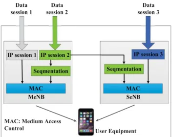
Fig. 1. The typical deployment of dual connectivity scenario for VL and RF spectra.
cellular systems, we will first estimate the required level of illumination for the proposed system model. Thereafter, we study the VLC-LTE dual connectivity feature performance and compare the results in term of user throughput. Finally, we apply resource allocation between two different spectra, i.e., RF and VL.
The remainder of this paper is structured as follows. Sec-tion II gives an overview of the proposed system model including VLC and LTE dual connectivity systems. Simulation results and discussions are presented in Section III. Conclu-sions are finally drawn in Section IV.
II. SYSTEMMODEL
Let us consider a system level model consisting of a single macrocell site covering a hexagonal shaped area and an indoor VLC system represented by a Li-Cell and located at macrocell-edge as shown in Fig. 1. Here, an indoor user equipment (UE) can simultaneously be connected to and receive data from the macrocell and Li-cell in the downlink. In the proposed system model, the macro eNB is considered as MeNB, which owns the access for UEs in the uplink direction and controls their mobility. Whilst, the Li-Cell is considered as SeNB which are coordinated by MeNB to serve the UEs in downlink only. The VLC link scenario and dual connectivity description will be detailed in next subsections.
A. VLC Link Scenario
A typical VLC system consists of an optical source or transmitter (Tx) that utilizes off-the-shelf light-emitting diodes (LEDs), an optical wireless channel, and an optical re-ceiver (Rx) which employs a photodiode (PD) such as p-type/intrinsic/n-type (PIN) PD. Among different link scenarios of OWC systems which are detailed in [8], the non-direct line-of-sight (NDLoS) scenario considers as the most appropriate one for VLC to fulfill the illumination and communication simultaneously. Since LEDs emit incoherent light, a practi-cal low-cost optipracti-cal carrier modulation for VLC is usually
achieved through intensity modulation (IM) direct detection (DD). In IM/DD scheme, the information is encoded in the envelope of the transmitted signal, and there is no phase information [9]. Due to the reduced cost and complexity, IM/DD is widely used at data rates below 10 Gbps [10]. The subsections below present the VLC system components in details.
1) Optical Source: VLC systems utilize commercially available off-the-shelf incoherent white LEDs (WLEDs) as a Tx. Incoherent WLED lamps usually consist of a significant number of single chips, each presenting a generalized Lam-bertian radiation pattern that can be expressed as [11]
R(φT) =
m+ 1
2π cos m(φ
T), φT ∈[−π/2, π/2]. (1)
Here, φT is the angle of irradiance, and m is the mode
number of the radiation lobe, which is given as [12]
m=− 0.693
ln(cos(φ1/2))
. (2)
Here,φ1/2is half power emission angle of the LED, namely
it is the view angle when radiant intensity is half of the value at 0◦. Mode number is specifying the directionality of the source, where higher m means higher directionality of the optical source. Most of LEDs haveφ1/2 = 60◦, namelym= 1. In this paper, we consider a LED lamp, which is consist of
20×20LED chips. The transmitted optical power of a LED chip is 20 mW. The lamp is positioned at the center of the ceiling in a typical office room.
2) Optical Receiver: At the Rx, the PD can be modeled as an effective areaAeff collecting the optical rays that come
from the Tx and strike the Rx at anglesφRsmaller thanΨFoV,
which is the PD’s field of view (FoV). The effective area of the PD is given as [13]
Aeff=
Arcos(φR), 0≤φR≤ΨFoV
0, φR>ΨFoV. (3)
Here,Ar= 2πr, is the area of a circular PD, andrdenotes its
radius. Therefore, only rays that fall within receiver’s FoV will be captured. In order to increase overall effective collection area, truncated spherical non-imaging concentrator, i.e., lens is attached to the PD. The optical gainG(φR)that provided
by the concentrator is given as [14]
G(φR) =
n2
sin2(φR), 0≤φR ≤ΨFoV
0, φR>ΨFoV.
(4) Here, n denotes the refractive index of the concentrator. Furthermore, an optical filter, with T(φR) transmission
co-efficient, can be deposited onto the concentrator surface or inserted between the concentrator and the PD. The optical filter is normally used to reduce all out-of-band natural and artificial light signals. Using of optical concentrator and filter can highly increase the detected power and decrease ambient noise, respectively and thus improve SNR [13]. The PD can be integrated with end-user devices such as laptops, tablets, and smartphones. PIN PD is employed as the Rx in this work.
3) Optical Channel: In order to make the optical wireless channel as simple as possible, only NDLoS link configuration is considered in this study. The optical LoS channels are considered as non-frequency selective and hence, for most purposes, the most important quantity which is characterizing such intensity-in intensity-out channel is the dual connectivity gainHLoS(0). The optical wireless channel dual connectivity
gain HLoS(0) is inversely proportional to the square of the distance between the Tx and Rx (the inverse square law) as [13]
HLoS(0) =(m+ 1)Aeff
2π(D)2 cos m(φ
T) cos(φR). (5)
Here, D denotes the Tx-Rx distance. If we consider a LED lamp, which is consist of a specific number N of LED chips and considering the contribution of optical concentrator and filter gains, the LoS average received optical powerPRxLoScan be written as
PLoS
Rx = N i=1
HLoS
i (0)×PLED,i×G(φR)×T(φR). (6)
Accordingly, the generated photocurrent(iph)at the output of
the PD is given by
iph=PRxLoS×Rλ. (7)
Here,Rλ(A/W) is the PD responsivity. However, in terms of
the noise at the Rx side, the noise comprises of 1) the shot noise σ2
sh, which is induced by the received photocurrent, 2)
background noiseσ2
b resulting from the ambient light sources,
3) dark current noiseσd2, that is caused by the reverse leakage current which flows through the PD in the absence of light, and 4) thermal noiseσ2thermal, which is induced by the receiver’s electronics such as the resistive element. The latter noise is generated independently of the received optical signal and has a Gaussian distribution. Consequently, the total noise variance defined as [13]
σ2
total=σ2sh+σ2b+σ2d+σth2. (8)
According to [13], the shot and thermal noise variances are given by
σ2
sh= 2qRλPRxB+ 2qIBI2B (9)
σ2
th=
8πkBTk
Gol
CpdArI2B2+16
π2k
BTkΓ
gm
CpdA2rI3B3. (10)
The other noise contributions in (8) can be obtained ac-cording to [13] (Equation 4.7). It is worth mentioning that the system model key parameters are given Table I. Consequently, the noise limited SNR at the PD side is given as [13]
SNR =(Rλ P
LoS Rx )2
σ2
total
. (11)
From (11), it can be seen that unlike the conventional RF chan-nels where the SNR is proportional to the average received powerPRx, the SNR in VLC channels is proportional toP2
Rx,
Fig. 2. Proposed VLC-LTE dual connectivity user plane architecture.
thus implying the need for higher optical power requirement and a limited path loss to deliver the same performance. Therefore, VLC technology is considered as a good candidate for future short-range communications.
B. VL-RF Dual Connectivity
LTE dual connectivity has been introduced in 3GPP release 12 specifications [6]. It is one of the promising technologies for the next-generation of wireless communication systems since it brings the possibility for the users to be connected simultaneously from two different eNBs. Therefore, it has the advantage of being able to double the user throughput, especially for cell-edge UEs, enhancing mobility robustness, and reducing signaling overhead towards the core, which is happening due to the frequent handover. In this study, we have extended the LTE dual connectivity concept through introducing the VL spectrum into the cellular architecture. A general user plane architecture of the proposed VLC-LTE dual connectivity version is presented in Fig. 2. The data session can be delivered to the UEs from three different possible directions. Thus, the UEs can use the resources of the MeNB only (depicted in gray), the SeNB only (depicted in blue) or aggregate both RF and VL resources (depicted in green), relying on whether offload or high throughput is to be favored. It is important to emphasize that the uplink channels are served by the MeNB. If an uplink channel becomes weak, then the corresponding UE will lose the connection to the network regardless of the existing connection with the SeNB. The dual connectivity is usually configured for low to medium mobility speed cases and supports indoor and outdoor, ideal and non-ideal backhaul scenarios. The control channel is terminated only at one node, usually the MeNB, and thus reduces handover activities and signaling overhead. Accordingly, all control messages are transmitted only between the MeNB and the UE. The dual connectivity concept was standardized for the RF spectrum only. Therefore, the use of dual connectivity with
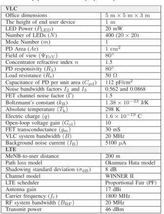
TABLE I
The key parameters of the proposed system model.
VLC
Office dimensions 5 m×5 m×3 m The height of end user device 1 m
LED Power (PLED) 20 mW
Number of LEDs (N) 400 (20×20) Mode Number (m) 1
PD Area (Ar) 1 cm2
Field of view(ΨFoV) 80◦
Concentrator refractive indexn 1.5 PD responsivity (Rλ) 80◦ Load resistance (Rs) 50Ω
Capacitance of PD per unit area (Cpd) 112 pF/cm2
Noise bandwidth factorsI2andI3 0.562 and 0.0868
FET channel noise factor (Γ) 1.5
Boltzmann’s constant (kB) 1.38×10⁻²³J/K
Absolute temperature(Tk) 298 K
Electric charge(q) 1.6×10⁻¹⁹C
Open-loop voltage gain(Gol) 10
FET transconductance(gm) 30 mS
VLC system bandwidth(B) 20 MHz Background noise current(IB) 5100μA
LTE
MeNB-to-user distance 200 m
Path loss model Okumura Hata model Shadowing standard deviation (σdB) 8 dB
Channel model WINNER II LTE scheduler Proportional Fair (PF) Antenna gain 17 dBi
Carrier frequency (fc) 1800 MHz
RF system bandwidth(BRF) 20 MHz
Transmit power 46 dBm
VL spectrum will offer a great opportunity to include VLC into the next generation of cellular systems. Hence, higher user throughput at and beyond cell-edge.
III. SIMULATIONRESULTS ANDDISCUSSIONS In this section, the characteristics of the proposed system are investigated through the simulation. The entries of VLC and LTE parameters are summarized in Table I.
A. Environment Illuminance
Since VLC technology delivers illumination and communi-cation simultaneously, it is important to guarantee the lighting function as well. The lighting function can be measured through the illuminanceE (horizontal light level) as [15]
E=I(0) cos
m(φ
T) cos (φR)
D2 . (12)
Here,I(0)is the center luminous intensity of the LED and it is provided by the manufacturers. The SI unit of illuminance is lux (lx). Illumination must comply with the lighting standards to ensure eye safety and avoid light flicker. For a typical environment over limited areas such as typical offices and rooms, an illuminance span of 200 – 1000 lx is required [13]. In terms of lighting level, the illumination was assessed at 1 m above the floor. The resultant horizontal illuminance is illustrated in Fig. 3. It can be seen that the standard illumination requirements for the proposed system model have been fulfilled.
/HQJWKxP
:LGWKyP
,OOXPLQDQFH
E
O[
Fig. 3. Horizontal illuminance (lx) (the optical source located at (0,0,3)).
/HQJWKyP
:LGWKyP
5HFHLYHGSRZHU
p
G%P
Fig. 4. Received optical power (dBm) (the optical source located at (0,0,3)).
B. SNR of VLC System
In order to compute the SNR for the proposed VLC system model, the received optical power (in dBm) has been computed according to (6) and it can be shown in Fig. 4. Consequently, the SNR as a function of the receiver’s position is shown in Fig. 5. It can be seen that the SNR values are high in the pro-posed model. This is due to that the optical signal encounters low path loss compared with RF signal because of the short distance between the SeNB and the UE. In our simulation, the whole UE horizontal plane has been considered. The resultant optical SNR was in the range of approximately (91–103) dB, as shown in Fig. 5. For the purpose of results validation, it is worth mentioning that such high SNR values have also been observed in [16].
C. UE Downlink Throughput
LTE system with one eNB is considered to enable the communications between the UE and the network. Users are assumed to be indoors in a building and distributed uniformly within the building. The distance between the eNB and the
/HQJWKxP
:LGWKyP
615G%
Fig. 5. The SNR of the proposed system model (the optical source located at (0,0,3)).
mobile user is assumed to be 200 m. Here, we have used a path loss model, which is relevant to the urban areas. It has been assumed that the buildings are of nearly uniform height. Hence, the total path loss can be calculated as [17]
LT=Ld+Lsh+Lp [dB]. (13)
Here,Ld,Lsh, andLp are the distance dependent path losses,
the shadowing losses, and the frequency-dependent penetra-tion losses, respectively. The Ld is assumed to be based on
Okumura-Hata model [18]. The shadowing losses are assumed to be log-normal distribution with zero mean and standard deviation of 8 dB. The wireless world initiative new radio II (WINNER II) channel model is used to generate the time-correlated fast fading channel. It has been considered that MeNB and SeNB are equipped with 20 MHz bandwidth. In this study, we examine two VLC-LTE dual connectivity scenarios as described in the following subsections.
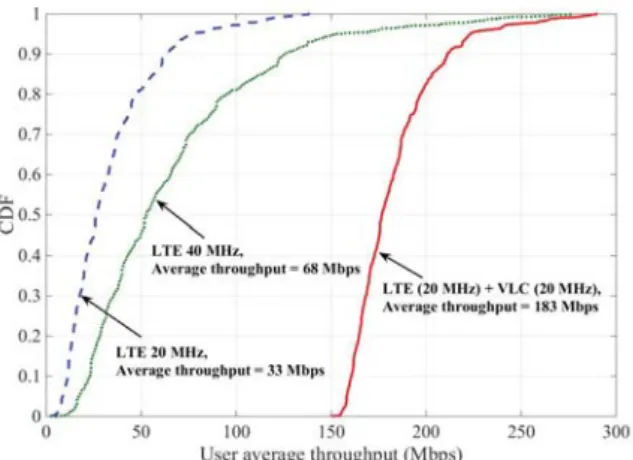
1) Single-User Scenario: In the first scenario, only one user is considered. The UE can be located at any position in the indoor environment within the coverage of both MeNB and SeNB. The average user throughput is presented in Fig. 6. It can be seen that when considering MeNB only with user bandwidth of 20 MHz, the achievable average throughput is about 33 Mbps. While the throughput is increased significantly to 183 Mbps when considering both MeNB and Li-Cell with 40 MHz combined spectrum, i.e., 20 MHz VLC and 20 MHz LTE. Furthermore, to make a fairer comparison with the later combined spectrum, we have also considered MeNB only with user bandwidth of 40 MHz. Consequently, the achievable average throughput for the given bandwidth is around 68 Mbps, which indicates that the proposed system provides more than double average throughput benefit than having only 40 MHz LTE stand alone. The significant increase in the throughput is due to the fact that all obtained SNR values for VLC link (as shown in Fig. 5) are yielding the maximum possible throughput by the LTE. Note that the minimum signal-to-noise-plus-interference ratio (SNIR) to achieve the peak throughput in LTE is 20 dB. Thus, the high SNR of
Fig. 6. The average user throughput.
VLC system has no impact on the peak throughput that LTE system is able to deliver today.
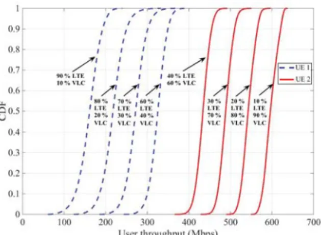
2) Two-User Scenario: Two users are considered in this scenario. Thus, we are trying to manage the resource allocation between the two different spectrums, i.e., RF and VL, with 20 MHz bandwidth for each. Here, the first UE reserves its data by utilizing different portions of RF and VL spectra. Whilst, the second user is served by the remaining resources of both spectrums, as illustrated in Fig. 7. For example, the first UE, which is denoted by the first curve at the left locates within the coverage of the MeNB, reserving 90 % of RF resources and 10%from VL spectrum. While the second UE, that is locate at the MeNB cell-edge, is other way around. The trends of resource allocation and user throughput are shown in Fig. 7. Accordingly, one can notice the significant throughput enhancement at the cell-edge when employing Li-Cell. Having this throughput over a specific bandwidth is the main result of having high SNR, as seen in III-B. Finally, it is worth to mention that unlike single-user scenario, it has been assumed in two-user scenario that the peak throughput is calculated by Shannon’s capacity. Thus the peak speed will be significantly higher compared with the LTE system.
IV. CONCLUSIONS
In this paper, we have extended the state-of-the-art dual connectivity in 3GPP LTE standard to include the VL spec-trum. The proposed system model employs one RF MeNB (macrocell) and one VL SeNB (Li-Cell). In terms of VLC system, an indoor NDLoS VLC link based on IM/DD has been considered. The simulation results have shown that there is a significant benefit of employing Li-Cell at and beyond macro cell-edge in terms of per-user average throughput. The results have further pointed out that when resource allocation applies, there is a remarkable enhancement of cell-edge user throughput. This is due to the high SNR values of VLCs systems. On the other hand, suitable environment illumination has been fulfilled in this work to match the standard illumina-tion criteria. Therefore we can conclude that VLC-LTE dual
Fig. 7. User throughput at different resource allocation percentages.
connectivity can play a vital role in the next generation of cellular systems.
ACKNOWLEDGMENT
The authors would like to acknowledge the support from the EU H2020 RISE TESTBED project (No. 734325), EU FP7 QUICK project (Grant No. PIRSES-GA-2013-612652), EP-SRC TOUCAN project (Grant No. EP/L020009/1), National Natural Science Foundation of China (Grant No. 61371110, 61622101 and 61571020 ), Key R&D Program of Shandong Province (Grant No. 2016GGX101014), Science and Technol-ogy Project of Guangzhou (Grant No. 201704030105), and Ministry of Higher Education & Scientific Research of Iraq (Grant No. 790).
REFERENCES
[1] H. J. Song and T. Nagatsuma, “Present and future of terahertz commu-nications,”IEEE Trans. Terahertz Science and Technology, vol. 1, no. 1, pp. 256–263, Sept. 2011.
[2] C.-X. Wang, F. Haider, X. Gao, X.-H. You, Y. Yang, D. Yuan, H. Aggoune, H. Haas, S. Fletcher, and E. Hepsaydir, “Cellular architecture and key technologies for 5G wireless communication networks,”IEEE Commun. Mag., vol. 52, no. 5, pp. 122–130, Feb. 2014.
[3] H. Haas. (2011, July) Wireless data from every light bulb [Online]. Available: http:// www.ted.com.
[4] N. Sklavos, M. Huebner, D. Goehringer, and P. Kitsos, System-Level Design Methodologies for Telecommunication, London: Springer, 2014. [5] PureLiFi [Online]. Available: http://www.purelifi.com.
[6] S. C. Jha, K. Sivanesan, R. Vannithamby, and A. T. Koc, “Dual connec-tivity in LTE small cell networks,” inProc. IEEE Globecom’14, Austin, USA, Dec. 2014, pp. 1205–1210.
[7] Nokia Networks. LTE Release 12 and beyond. White Paper [Online]. Available: https://resources.ext.nokia.com/asset/200174.
[8] R. Ramirez-Iniguez, S. M. Idrus, and Z. Sun,Optical Wireless commu-nications, Boca Raton: CRC press, 2008.
[9] S. Dimitrov and H. Haas, Principles of LED light communications towards networked Li-Fi, London: Cambridge University Press, 2015. [10] M. S. Islim et al., “Towards 10 Gb/s orthogonal frequency division
multiplexing-based visible light communication using a GaN violet mi-croLED,”Photonics Research, vol. 5, no. 2, A35, Apr. 2017.
[11] F. R. Gfeller and U. H. Bapst, “Wireless in-house data communication via diffuse infrared radiation,” inProc. IEEE, vol. 67, no. 11, pp. 1474– 1486, Nov. 1979.
[12] A. Al-Kinani, C.-X. Wang, H. Haas, and Y. Yang, “Characterization and modeling of visible light communication channels,” inProc. IEEE VTC’16-Spring, Nanjing, China, May 2016, pp. 1–5.
[13] Z. Ghassemlooy, W. Popoola, and S. Rajbhandari, 1st Ed., Optical Wireless Communications: System and Channel Modelling with MATLAB, New York: CRC press, 2013.
[14] O. Bouchet, Wireless Optical Communications, London: John Wiley & Sons, 2012.
[15] T. Komine and M. Nakagawa, “Fundamental analysis for visible-light communication system using LED lights,”IEEE Trans. Consumer Elec-tronics, vol. 50, no. 1, pp. 100–107, Feb. 2004.
[16] L. Zeng, D. O’Brien, H. Le-Minh, K. Lee, D. Jung and Y. Oh, “Improvement of date rate by using equalization in an indoor visible light communication system,” inProc. IEEE ICECS’08, Shanghai, China, June 2008, pp. 678–682.
[17] F. Haider, E. Hepsaydir, and N. Binucci, “Performance analysis of LTE-advanced networks in different spectrum bands,” inProc. IEEE WiAd’11, London, UK, June 2011, pp. 230–234.
[18] M. C. Jeruchim, P. Balaban, and K. S. Shanmugan, 2nd Ed.,Simulation of Communication System Modeling, Methodology, and Techniques, New York: Kluwer Acadimic Plenum, 2000.