A Novel Grid Current Compensator for Grid-Connected
Distributed Generation under Nonlinear Loads with Fuzzy
Logic Controller
Shaik Roshna
1,
2Sk.Meera Shareef,
3M.BalaSubba Reddy
1
M.Tech, Scholar,
2Assistant Professor,
3Associate Professor& H.O.D
Dept of EEE, Prakasam Engineering College, Kandukur.
Abstract— This paper introduces an advanced current control strategy for grid-connected operations of distributed generation (DG), which supports the DG to transfer a sinusoidal current into the utility grid despite the distorted grid voltage and nonlinear local load conditions. The proposed fuzzy logic controller based current controller is designed in the synchronous reference frame and compared with conventional PI controller and with combination of a proportional– integral (PI) controller and a repetitive controller (RC). An RC serves as a bank of resonant controllers, which can compensate a large number of harmonic components with a simple delay function. Hence, the control strategy can be greatly simplified. In addition, the proposed control method does not require the local load current measurement or harmonic analysis of the grid voltage. Therefore, the proposed control method can be easily adopted into the traditional DG control system without installation of extra hardware. Despite the reduced number of sensors, the grid current quality is significantly improved compared with the traditional methods with the PI controller and PI-RC controller. The operation principle of the proposed control method is analyzed in detail, and its effectiveness is validated through simulation results.
Index Terms—Distributed generation (DG), grid-connected inverter, harmonic compensation, nonlinear load, repetitive control performance.
I. INTRODUCTION
The use of renewable energy sources, such as wind turbines, Photovoltaic, and fuel cells, has greatly increased in recent decades to address concerns about the global energy crisis, Depletion of fossil fuels, and environmental pollution problems. As a result, a large number of renewable energy sources have been integrated in power distribution systems in the form of
distributed generation (DG) [1]. DG systems can offer many advantages over traditional power generation, such as small size, low cost, high efficiency, and clean electric power generation. A DG system is typically operated in a grid-connected mode where the maximum available power is extracted from energy sources and transferred to the utility grid [2]–[8].
The grid current quality therefore relies heavily on the accuracy of the grid voltage harmonic analysis; if the harmonic components in the grid voltage are varied, it is difficult to maintain a good grid current quality. Moreover, the searching algorithm requires a large calculation time and can operate only offline. In [6]–[8] and [18], several selective harmonic compensators are developed using a resonant controller, in which the resonant controller tuned at the sixth multiple of the fundamental frequency is added to eliminate the effect of fifth and seventh harmonic grid voltages on the grid current quality. The grid current quality can be improved, due to the additional resonant controllers.
A repetitive controller (RC) serves as a bank of resonant controllers to compensate a large number of harmonic components with a simple delay structure. However, despite the effectiveness of the RC in harmonic compensation, the traditional RC has a long delay time, which regularly limits the dynamic response of the current controller. For example, as reported in [12], the dynamic response of the grid current under a step change of the current reference is approximately 150 ms, which is extremely slow compared with other control methods. In addition, even with the utilization of the RC, this method is unable to bring the THD of the grid current lower than the limited value 5% in the IEEE 1547 standards.
presence of nonlinear loads in the local load of the DG also causes a negative impact on the grid current quality [13]. To address this problem, the local load current measurement and a load current feed forward loop are regularly adopted [13]. Furthermore, most aforementioned studies consider and separately tackle the impact of distorted grid voltage or the nonlinear local load; none of them simultaneously takes into account those issues. To overcome the limitations of aforementioned studies, this paper proposes an advanced current control strategy for the grid-connected DG, which makes the grid current sinusoidal by simultaneously eliminating the effect of nonlinear local load and grid voltage distortions. First, the influence of the grid voltage distortions and nonlinear local load on the grid current is determined. Then, an advanced control strategy is introduced to address those issues. The proposed current controller is designed in the d–q reference frame and is composed of a PI and an RC.
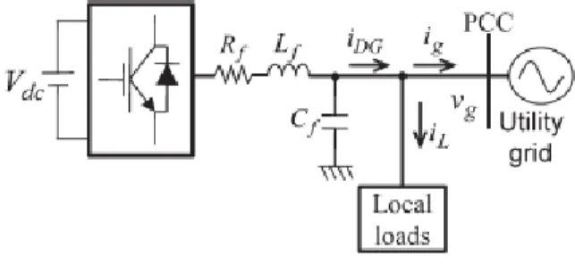
Fig.1. System configuration of a grid-connected DG system with local load
One single RC can compensate a large number of harmonic components with a simple delay function. Hence, the control strategy can be greatly simplified. Another advantage of the proposed control method is that it does not demand the local load current measurement and the harmonic analysis of the grid voltage. Therefore, the proposed control method can be easily adopted into the traditional DG control system without the installation of extra hardware. Despite the reduced number of sensors, the performance of the proposed grid current controller is significantly improved compared with that of the traditional PI current controller. In addition, with the combination of the PI and RC, the dynamic response of the proposed current controller is also greatly enhanced compared with that of the traditional RC. The feasibility of the proposed control strategy is completely verified by simulation results.
II. SYSTEM CONFIGURATION AND ANALYSIS OF GRID VOLTAGE DISTORTION AND
NONLINEAR LOCAL LOAD
Fig. 1 shows the system configuration of a three-phase DG operating in grid-connected mode. The system consists of a dc power source, a voltage-source inverter (VSI), an output LC filter, local loads, and the utility grid. The purpose of the DG system is to supply power to its local load and to transfer surplus power to the utility grid at the PCC. To guarantee high-quality power, the current that the DG transfers to grid (ig) should be balanced, sinusoidal, and have a low THD value. However, because of the distorted grid voltage and nonlinear local loads that typically exist in the power system, it is not easy to satisfy these requirements.
A. Effect of Grid Voltage Distortion
To assess the impact of grid voltage distortion on the grid current performance of the DG, a model of the grid-connected DG system is developed, as shown in Fig. 2. In this model, the VSI of the DG is simplified as voltage source (vi). The inverter transfers a grid current (ig) to the utility grid (vg). For simplification purpose, it is assumed that the local load is not connected into the system. In Fig. 2(a), the voltage equation of the system is given as
Where Rf and Lf are the equivalent resistance and inductance
of the inductor Lf , respectively.
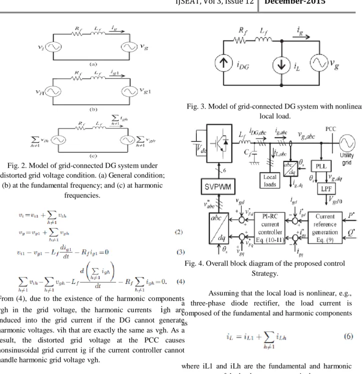
Fig. 2. Model of grid-connected DG system under distorted grid voltage condition. (a) General condition;
(b) at the fundamental frequency; and (c) at harmonic frequencies.
From (4), due to the existence of the harmonic components vgh in the grid voltage, the harmonic currents
i
gh are induced into the grid current if the DG cannot generate harmonic voltages. vih that are exactly the same as vgh. As a result, the distorted grid voltage at the PCC causes nonsinusoidal grid current ig if the current controller cannot handle harmonic grid voltage vgh.B. Effect of Nonlinear Local Load
Fig. 3 shows the model of a grid-connected DG system with a local load, whereby the local load is represented as a current source iL, and the DG is represented as a controlled current source iDG. According to Fig. 3, the relationship of DG current iDG, load current iL, and grid current ig is described as
Fig. 3. Model of grid-connected DG system with nonlinear local load.
Fig. 4. Overall block diagram of the proposed control Strategy.
Assuming that the local load is nonlinear, e.g., a three-phase diode rectifier, the load current is composed of the fundamental and harmonic components as
where iL1 and iLh are the fundamental and harmonic components of the load current, respectively.
Substituting (6) into (5), we have
or PR controllers, cannot realize this demand because they lack the capability to regulate harmonic components.
III. PI +RC BASED CONTROL SCHEME
To enhance grid current quality, an advanced current control strategy, as shown in Fig. 4, is introduced. Although there are several approaches to avoid the grid voltage sensors and a phase-locked loop (PLL) [19], Fig. 4 contains the grid voltage sensor and a PLL for simple and effective implementing of the proposed algorithm, which is developed in the d–q reference frame.
The proposed control scheme is composed of three main parts: the PLL, the current reference generation scheme, and the current controller. The operation of the PLL under distorted grid voltage has been investigated, in detail, in [20]; therefore, it will not be addressed in this paper. As shown in Fig. 4, the control strategy operates without the local load current measurement and harmonic voltage analysis on the grid voltage. Therefore, it can be developed without requiring additional hardware. Moreover, it can simultaneously address the effect of nonlinear local load and distorted grid voltage on the grid current quality.
Fig.5. Block diagram of the current controller.
A. Current Reference Generation
As shown in Fig. 4, the current references for the current controller can be generated in the d–q reference frame based on the desired power and grid voltage as follows [14]:
where P∗ and Q∗ are the reference active and reactive power, respectively; vgd represents the instantaneous grid voltage in the d–q frame; and i∗ gd and i∗ gq denote the direct and quadrature components of the grid current, respectively.
Under ideal conditions, the magnitude of vgd has a constant value in the d–q reference frame because the grid voltage is pure sinusoidal. However, if the grid voltage is distorted, the magnitude of vgd no longer can be a constant value. As a consequence, reference current i∗ gd and i∗ gq cannot be constant in (8). To overcome this problem, a low-pass filter (LPF) is used to obtain the average value of vgd, and the d–q reference currents are modified as follows:
where Vgd0 is the average value of vgd, which is obtained through the LPF in Fig. 4.
B. Current Controller
An advanced current controller is proposed by using a PI and an RC in the d–q reference frame. The block diagram of the current controller is shown in Fig. 5. The open-loop transfer function of the PI and RC in a discrete-time domain is given respectively in
traditional RC suffers the severe drawback of a very slow dynamic response due to the long delay time by N samples. To remove the delay problem of the traditional RC, we consider only the (6n ± 1)th (n = 1, 2, 3 . . .) harmonics because they are dominant components in three-phase systems. The time delay of the RC in (13) is thereby reduced six times compared with the traditional one as N/6 [21].
TABLE I
SYSTEM PARAMETERS
IV PROPOSED FUZZY LOGIC CONTROLLER
A. Structure of fuzzy logic controller
Fuzzy controller the word Fuzzy means vagueness. Fuzziness occurs when the boundary of piece of information is not clear-cut. Fuzzy set theory exhibits immense potential for effective solving of the uncertainty in the problem. Fuzzy set theory is an excellent mathematical tool to handle the uncertainty arising due to vagueness.
Understanding human speech and recognizing handwritten characters are some common instances where fuzziness manifests. Fuzzy set theory is an extension of classical set theory where elements have varying degrees of membership. Fuzzy logic uses the whole interval between 0 and 1 to describe human reasoning.
In FLC the input variables are mapped by sets of membership functions and these are called as ―FUZZY SETS‖. Fuzzy set comprises from a membership function which could be defines by parameters. The value between 0 and 1 reveals a degree
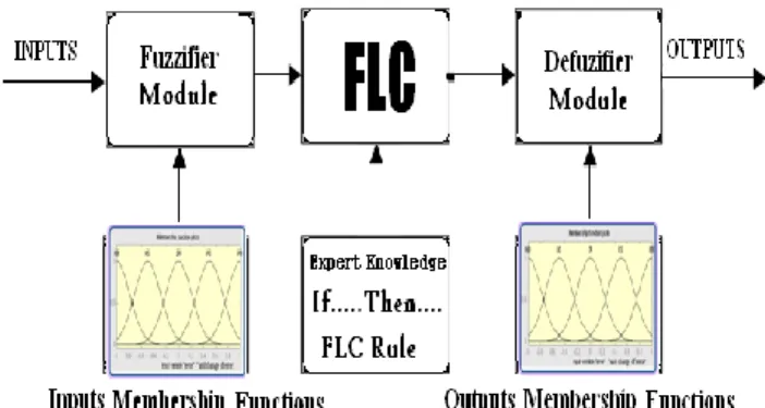
of membership to the fuzzy set. The process of converting the crisp input to a fuzzy value is called as ―fuzzificaton.‖ The output of the Fuzzier module is interfaced with the rules.
The basic operation of FLC is constructed from fuzzy control rules utilizing the values of fuzzy sets in general for the error and the change of error and control action. Basic fuzzy module is shown in Fig.6. The results are combined to give a crisp output controlling the output variable and this process is called as ―defuzzification‖
Fig.6. Fuzzy Basic Module
B. Fuzzy rules
TABLE II: FUZZY RULES
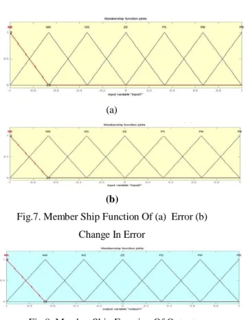
C. MEMBERSHIP FUNCTIONS
(a)
(b)
Fig.7. Member Ship Function Of (a) Error (b)
Change In Error
Fig.8. Member Ship Function Of Output
V. SIMULATION RESULTS
A simulation model of the DG system is built by PSIM simulation software to verify the effectiveness of the proposed control method. The system parameters are given in Table I. In the simulation, three cases are taken into account.
1) Case I: The grid voltage is sinusoidal and the linear local load is used.
2) Case II: The grid voltage is sinusoidal and the nonlinear local load is used.
3) Case III: The grid voltage is distorted and the nonlinear local load is used.
In all test cases, the reference grid current is set at i∗ gd = 10 A and i∗ gq = 0, and the conventional PI current controller and the proposed current controller are investigated to compare their control performances. Fig. 9 depicts the steady-state performance of the grid connected DG by using the conventional PI current controller, in which the waveforms of grid voltage (vg,abc), grid current (ig,abc), local load current (iL,abc), and DG current (iDG,abc) are plotted. As shown in Fig. 9, the PI current controller is able to offer a good performance only in Case I, when the grid voltage is ideal sinusoidal and the local load is linear. In the other
circumstances, due to the effect of distorted grid voltage and the nonlinear local load, the PI current controller is unable to transfer a sinusoidal grid current to the utility grid. In fact, because of the popular use of nonlinear loads in the DG local load and distribution system, the ideal sinusoidal condition of the grid voltage is very rare.
On the other hand, the conditions, as given in Cases II and III, frequently occur in practice. As a result, the conventional PI controller is insufficient to offer a good quality of the grid current. To demonstrate the superiority of the proposed current controller over the traditional PI controller, the DG system with the proposed current controller is also simulated, and the results are shown in Fig. 9.
As shown in the results, the proposed control strategy can provide a good quality grid current, i.e., sinusoidal grid currents, despite the distorted grid voltage and nonlinear local load conditions. Therefore, with the aid of the RC in the proposed current controller, the distorted grid voltage and nonlinear load current no longer affect the grid current quality.
A. Simulation result with PI controller
(a)
(c)
Fig.9. Simulation results with the PI current controller: (a) Case I;(b) Case II; and (c) Case III.
(a)
(b)
Fig.10. % THD at (a) case I as 1.63
(b) case II as 12.3 (c) case III as 20.11
B. Simulation result with PI-RC controller:
(a)
(b)
(c)
Fig.11. Simulation results with the PI-RC current
controller: (a) Case I ;(b) Case II; and (c) Case III
(b)
(c)
Fig.12. % THD at (a) case I as 1.60
(b) case II as 1.80(c) case III as 1.92
C. Simulation results with frequency variations
(a)
(b)
Fig. 13. Simulation results of the proposed PI-RC current
controller under grid frequency variations
(a) from 50 to 49 Hz and (b) from 50 to 51 Hz.
7.4 Simulation result with fuzzy logic controller:
(a)
(b)
(c)
Fig.14. Simulation results with the proposed FUZZY
current controller:
(a)
(b)
(c)
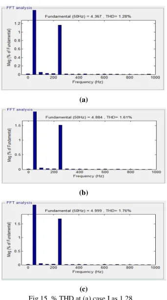
Fig.15. % THD at (a) case I as 1.28
(b) case II as 1.61 (c) case III as 1.76
TABLE III
SUMMARY OF THD VALUES OF GRID CURRENT
WITH PI, PI-RC CONTROLLER AND PROPOSED
FUZZY BASED CURRENT CONTROLLERS
VI. CONCLUSION
This paper has proposed an advanced current control strategy for the grid-connected DG to simultaneously eliminate the effect of grid voltage distortion and nonlinear local load on the grid current. The simulation results established that the DG with the proposed current controller can sufficiently transfer a sinusoidal current to the utility grid, despite the nonlinear local load and distorted grid voltage conditions. The proposed fuzzy based current control scheme can be implemented without the local load current sensor and harmonic analysis of the grid voltage; therefore, it can be easily integrated in the conventional control scheme without installation of extra hardware. Despite the reduced number of current sensors, the quality of the grid current is significantly improved: the THD value of the grid current is decreased considerably compared with that achieved by using the conventional PI current controller. In addition, the proposed current controller also maintained a good quality of grid current under grid frequency variations. Moreover, the dynamic response of the grid current controller was also greatly enhanced compared with that of the traditional PI-RC, due to the fuzzy and the reduced RC delay time.
REFERENCES
[1] R. C. Dugan and T. E. McDermott, ―Distributed generation,‖ IEEE Ind. Appl. Mag., vol. 8, no. 2, pp. 19–25, Mar./Apr. 2002.
[2] F. Blaabjerg, R. Teodorescu, M. Liserre, and A. V. Timbus, ―Overview of control and grid synchronization for distributed power generation systems,‖ IEEE Trans. Ind. Electron., vol. 53, no. 5, pp. 1398–1409, Oct. 2006.
[3] J. A. Suul, K. Ljokelsoy, T. Midtsund, and T. Undeland, ―Synchronous reference frame hysteresis current control for grid converter applications,‖ IEEE Trans. Ind. Appl., vol. 47, no. 5, pp. 2183–2194, Sep./Oct. 2011.
[4] Q. Zeng and L. Chang, ―An advanced SVPWM-based predictive current controller for three-phase inverters in distributed generation systems,‖ IEEE Trans. Ind. Electron., vol. 55, no. 3, pp. 1235– 1246, Mar. 2008.
[5] S. Buso and P. Mattavelli, ―Digital control in power electronics,‖ in Synthesis Lectures on Power
% THD PI
Controller
PI-RC
Controller
Fuzzy Logic
Controller
Case I 1.63 1.60 1.28
Case II 12.30 1.80 1.61
Electronics. San Rafael, CA, USA: Morgan & Claypool, 2006.
[6] C. A. Busada, S. Gomez Jorge, A. E. Leon, and J. A. Solsona, ―Current controller based on reduced order generalized integrators for distributed generation systems,‖ IEEE Trans. Ind. Electron., vol. 59, no. 7, pp. 2898– 2909, Jul. 2012.
[7] M. Liserre, R. Teodorescu, and F. Blaabjerg, ―Multiple harmonics control for three-phase grid converter systems with the use of PI-RES current controller in a rotating frame,‖ IEEE Trans. Power Electron., vol. 21, no. 3, pp. 836–841, May 2006.
[8] M. Castilla, J. Miret, A. Camacho, J. Matas, and L. G. de Vicuna, ―Reduction of current harmonic distortion in three-phase grid-connected photovoltaic inverters via resonant current control,‖ IEEE Trans. Ind. Electron., vol. 60, no. 4, pp. 1464– 1472, Apr. 2013.
[9] R.-J. Wai, C.-Y. Lin, Y.-C. Huang, and Y.-R. Chang, ―Design of highperformance stand-alone and grid-connected inverter for distributed generation applications,‖ IEEE Trans. Ind. Electron., vol. 60, no. 4, pp. 1542–1555, Apr. 2013.
[10] I. J. Balaguer, Q. Lei, S. Yang, U. Supatti, and F. Z. Peng, ―Control for grid-connected and intentional islanding operations of distributed power generation,‖ IEEE Trans. Ind. Electron., vol. 58, no. 1, pp. 147–157, Jan. 2011.
[11] G. G. Pozzebon, A. F. Q. Goncalves, G. G. Pena, N. E. M. Mocambique, and R. Q. Machado, ―Operation of a three-phase power converter connected to a distribution system,‖ IEEE Trans. Ind. Electron., vol. 60, no. 5, pp. 1810–1818, May 2013.
[12] Q.-C. Zhong and T. Hornik, ―Cascaded current-voltage control to improve the power quality for a grid-connected inverter with a local load,‖ IEEETrans. Ind. Electron., vol. 60, no. 4, pp. 1344– 1355, Apr. 2013.
[13] Z. Yao and L. Xiao, ―Control of single-phase grid-connected inverters with nonlinear loads,‖ IEEE Trans. Ind. Electron., vol. 60, no. 4, pp. 1384– 1389, Apr. 2013.
[14] Z. Liu, J. Liu, and Y. Zhao, ―A unified control strategy for three-phase inverter in distributed generation,‖ IEEE Trans. Power Electron., vol. 29, no. 3, pp. 1176–1191, Mar. 2014.
[15] IEEE Application Guide for IEEE Std 1547, IEEE Standard for Interconnecting Distributed
Resources with Electric Power Systems, IEEE Std. 1547.2-2008, 2008.
[16] R. Teodorescu, F. Blaabjerg, M. Liserre, and P. C. Loh, ―Proportionalresonant controllers and filters for grid-connected voltage-source converters,‖ Proc. Inst. Elect. Eng.—Elect. Power Appl., vol. 153, no. 5, pp. 750–762, Sep. 2006.
SHAIK ROSHNA currently pursuing her M.Tech in power electronics in prakasam engineering college, kandukur, andra pradesh, india affiliated to jntu university, kakinada. She has done her B.Tech degree from PACE college of engineering, affiliated to jnt university, kakinada, andhra pradesh, India and her fields of interest include power electronic drives and renewable energy sources and advanced controllers.
SK. MEERA SHAREEF presently working as Assistant professor in prakasam engineering college, kandukur, andhra pradesh, India. Completed M.Tech from jnt university, kakinada. His fields of interest include non conventional energy sources, advanced control techniques and electrical drives.