A Predictive Control Scheme for Enhancement of Active
Power Filter Performance
Kondapalli Paparao1, Pithani Suresh2, Nammi Sagar Teja Yadav3 Asst. Professor, Department of EEE, KIET, Kakinada, India.1 Asst. Professor, Department of EEE, KIET, Kakinada, India.2 Asst. Professor, Department of EEE, JNTUK, Kakinada, India.3
Abstract—A dynamic power channel actualized with a four-leg voltage-source inverter utilizing a prescient control plot is exhibited. The utilization of a four-leg voltage-source inverter permits the pay of current consonant parts, and additionally lopsided current created by single-stage nonlinear burdens. A point by point yet basic numerical model of the dynamic power channel, including the impact of the comparable power framework impedance, is determined and used to plan the prescient control calculation. A fuzzy controller is intended to moderate the aggregate consonant mutilation. The remuneration execution of the proposed dynamic power channel and the related control conspire under unfaltering state and transient working conditions is shown through reproductions utilizing MATLAB/SIMULINK condition.
List Terms—Active power channel, current control, four-leg converters, prescient control, fuzzy controller.
I. Presentation
Inexhaustible age influences control quality because of its nonlinearity, since sun oriented age plants and wind control generators must be associated with the matrix through high-control static PWM converters . The non uniform nature of energy age straightforwardly influences voltage control and makes voltage bending in control frameworks. This new situation in control dissemination frameworks will require more modern pay procedures.
Albeit dynamic power channels executed with three-stage four-leg voltage-source inverters (4L-VSI) have just been exhibited in the specialized writing , the essential commitment of this paper is a prescient control calculation composed and actualized particularly for this application. Generally, dynamic power channels have been controlled utilizing pretuned controllers, for example, PI-type or versatile, for the present and also for the dc-voltage circles . PI controllers must be outlined in light of the comparable straight model, while prescient controllers utilize the nonlinear model, which is nearer to genuine working
conditions. A fuzzy controller is additionally outlined in the place of PI controller to decrease the music. An exact model acquired utilizing prescient controllers enhances the execution of the dynamic power channel, particularly amid transient working conditions, since it can rapidly take after the present reference flag while keeping up a steady dc-voltage.
Up until now, usage of prescient control in control converters have been utilized basically in enlistment engine drives. On account of engine drive applications, prescient control speaks to an exceptionally natural control conspire that handles Multi variable attributes, improves the treatment of dead-time remunerations, and licenses beat width modulator substitution. In any case, these sorts of utilizations display detriments identified with motions and precariousness made from obscure load parameters. One preferred standpoint of the proposed calculation is that it fits well in dynamic power channel applications, since the power converter yield parameters are outstanding . These yield parameters are gotten from the converter yield swell channel and the power framework equal impedance. The converter yield swell channel is a piece of the dynamic power channel outline and the power framework impedance is acquired from understood standard systems . On account of obscure framework impedance parameters, an estimation strategy can be utilized to infer a precise R–L proportional impedance model of the framework .
This paper introduces the numerical model of the 4L-VSI and the standards of task of the proposed prescient control plot, including the outline technique. The total portrayal of the chose current reference generator executed in the dynamic power channel is additionally introduced. At last, the proposed dynamic power channel and the adequacy of the related control plot remuneration are exhibited through MATLAB/SIMULINK condition.
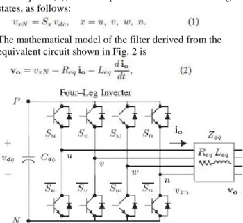
A dynamic power channel is associated in parallel at the purpose of basic coupling to remunerate current sounds, current unbalance, and responsive power. It is made by an electrolytic capacitor, a four-leg PWM converter, and a first-arrange yield swell channel, as appeared in Fig. 1. This circuit considers the power framework comparable impedance Zs , the converter yield swell channel impedance Zf , and the heap impedance ZL . The four-legPWMconverter topology is appeared in Fig. 2. This converter topology is like the regular three-stage converter with the fourth leg associated with the unbiased transport of the framework. The fourth leg expands changing states from 8 (23) to 16 (24 ), enhancing control adaptability and yield voltage quality, and is reasonable for current unequal Remuneration.
Fig 1. Three-phase equivalent circuit of the proposed shunt active power filter.
The voltage in any leg x of the converter, measured from the
neutral point (n), can be expressed in terms of switching states, as follows:
The mathematical model of the filter derived from the equivalent circuit shown in Fig. 2 is
Fig. 2. Two-level four-leg PWM-VSI topology
where Req and Leq are the 4L-VSI output parameters expressed
as Thevenin impedances at the converter output terminals Zeq .
Therefore, the Thevenin equivalent impedance is determined
by a series connection of the ripple filter impedance Zf and a
parallel arrangement between the system equivalent impedance Zs and the load impedance ZL
(3) For this model, it is assumed that ZL _ Zs , that
the resistive part of the system’s equivalent impedance
is neglected, and that the series reactance is in the range of 3–7% p.u., which is an acceptable approximation of the real system. Finally, in (2) Req = Rf and Leq = Ls +
Lf .
III. DIGITAL PREDICTIVE CURRENT CONTROL.
The square graph of the proposed computerized prescient current control conspire is appeared in Fig. 3. This control conspire is fundamentally a streamlining calculation and, hence, it must be executed in a chip. Thusly, the examination must be produced utilizing discrete arithmetic keeping in mind the end goal to consider extra confinements, for example, time deferrals and approximations The principle normal for prescient control is the utilization of the framework model to anticipate the future conduct of the factors to be controlled. The controller utilizes this data to choose the ideal exchanging state that will be connected to the power converter, as indicated by predefined streamlining criteria. The prescient control calculation is anything but difficult to execute and to comprehend, and it can be actualized with three primary pieces, as appeared in Fig. 3.
Fig. 3. Proposed prescient advanced current control piece outline.
1) Current Reference Generator: This unit is intended to create the required current reference that is utilized to remunerate the bothersome load current parts. For this situation, the systemvoltages, the heap streams, and the dc-voltage converter are estimated, while the impartial yield present and unbiased load current are produced straightforwardly from these signs (IV).
framework display must be spoken to in a discrete time space [22]. The discrete timemodel comprises of a recursive framework condition that speaks to this expectation framework. This implies for a given examining time Ts , knowing the converter exchanging states and control factors atinstant kTs , it is conceivable to anticipate the following states at any moment [k + 1]Ts .Due to the main request nature of the state conditions that depict the model in (1)–(2), an adequately exact first-arrange estimate of the subordinate is considered in this paper
(4)
The 16 possible output current predicted values can be
obtained from (2) and (4) as
(5)
As shown in (5), in order to predict the output current io at the instant (k + 1), the input voltage value vo and the converter output voltage vxN , are required. The algorithm calculates all 16 values associated with the possible combinations that the state variables can achieve.
3) Cost Function Optimization: In order to select the
optimal switching state that must be applied to the power converter, the 16 predicted values obtained for io[k + 1] are compared with the reference using a cost function g, as follows:
(6)
The yield current (io) is equivalent to the reference (i∗o ) when
g = 0. In this manner, the enhancement objective of the cost work is
to accomplish a g esteem near zero. The voltage vector vxN that
limits the cost work is picked and after that connected at the
next examining state. Amid each examining state, the exchanging
express that creates the base estimation of g is chosen from the 16 conceivable capacity esteems. The
calculation chooses the exchanging state that delivers this insignificant esteem and applies it to the converter amid the k + 1 state.
4) CURRENT REFERENCE GENERATOR
A dq-based current reference generator plot is utilized to get the dynamic power channel current reference signals. This plan shows a quick and precise flag following capacity. This trademark stays away from voltage variances that fall apart the present reference flag influencing remuneration execution [28]. The present reference signals are gotten from the comparing load streams as appeared in Fig. 5. This module computes the reference flag streams required by the converter to repay receptive power, current consonant, and current awkwardness. The uprooting power factor
(sin φ(L) ) and the greatest aggregate consonant
mutilation of the heap (THD(L) ) characterizes the connections between the obvious power required by the dynamic power channel, concerning the heap, as appeared
(7)
where the estimation of THD(L) incorporates the most extreme compensable consonant present, characterized as twofold the examining recurrence fs . The recurrence of the greatest current consonant segment that can be repaid is equivalent to one portion of the converter exchanging recurrence.
The dq-based plan works in a pivoting reference outline; subsequently, the deliberate streams must be increased by the sin(wt) and cos(wt) signals. By utilizing dq-change, the d current segment is synchronized with the relating stage to-nonpartisan framework voltage, and the q current segment is stage moved by 90◦. The sin(wt) and cos(wt) synchronized
.
(8)
A low-pass filter (LFP) extracts the dc component of the phase currents id to generate the harmonic reference components −_id . The reactive reference components of the phase-currents are obtained by phase-shifting the corresponding ac and dc components of iq by 180◦. In order to keep the dc-voltage constant, the amplitude of the converter reference current must be modified by adding an active power reference signal ie with the d-component, as will be explained in Section IV-A. The resulting signals id and iq are transformed back to a three-phase system by applying the inverse Park and Clark transformation, as shown in (9). The cutoff frequency of the LPF used in this paper is 20 Hz.
(9)
The current that flows through the neutral of the load is compensated by injecting the same instantaneous value obtained from the phase-currents, phase-shifted by 180◦, as shown next
(10)
One of the significant points of interest of the dq-based current reference generator conspire is that it permits the usage of a straight controller in the dc-voltage control circle. Notwithstanding, one imperative disservice of the dq-based current reference outline calculation used to produce the present reference is that a secondorder symphonious part is created in id and iq under lopsided working conditions. The abundancy of this consonant relies upon the percent of lopsided load current (communicated as the connection between the negative arrangement current iL,2 and the positive succession current iL,1 ). The second-arrange symphonious can't be expelled from id and iq , and in this manner produces a third consonant in the reference current when it is changed over back to abc outline [31]. Fig. 6 demonstrates the percent of framework current lopsidedness and the percent of third consonant
framework current, in capacity of the percent of load current awkwardness. Since the heap current does not have a third symphonious, the one created by the dynamic power channel streams to the power framework.
Fig 4. dq-based Current Reference Generator Block Diagram.
IV. Fuzzy controller
Lately, the number and assortment of uses of fuzzy rationale have expanded fundamentally. The applications go from customer items, for example, cameras, camcorders, clothes washers, and microwave stoves to modern process control, restorative instrumentation, choice emotionally supportive networks, and portfolio choice.
To comprehend why utilization of fuzzy rationale has developed, you should first comprehend what is implied by fuzzy rationale. Fuzzy rationale has two distinct implications. In a limited sense, fuzzy rationale is a consistent framework, which is an expansion of multivalve rationale. Be that as it may, in a more extensive sense fuzzy rationale (FL) is relatively synonymous with the hypothesis of fuzzy sets, a hypothesis which identifies with classes of items with unsharp limits in which participation involves degree. In this point of view, fuzzy rationale in its thin sense is a branch of fl. Indeed, even in its more tight definition, fuzzy rationale varies both in idea and substance from customary multivalve sensible frameworks.
figuring with words abuses the resistance for imprecision and consequently brings down the cost of arrangement. Another fundamental idea in FL, which assumes a focal part in the vast majority of its applications, is that of a fuzzy if-then run or, basically, fuzzy run the show. Despite the fact that control based frameworks have a long history of utilization in Artificial Intelligence (AI), what is absent in such frameworks is an instrument for managing fuzzy consequents and fuzzy precursors. In fuzzy rationale, this system is given by the math of fuzzy tenets. The analytics of fuzzy guidelines fills in as a reason for what may be known as the Fuzzy Dependency and Command Language (FDCL).
V.SIMULATION RESULTS
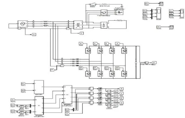
A reproduction display for the three-stage four-leg PWM converter with the parameters appeared in Table I has been created utilizing MATLAB-Simulink . The goal is to check the present symphonious pay adequacy of the proposed control plot under various working conditions. A six-beat rectifier was utilized as a nonlinear load. The proposed prescient control calculation was customized utilizing a S-work hinder that permits reenactment of a discrete model that can be effortlessly actualized in a constant interface (RTI) on
the dSPACE DS1103 R&D control board.
Reproductions were performed considering a 20 [μs] of
test time. In the recreated comes about appeared in Fig. 8, the dynamic channel begins to remunerate at t = t1 . Right now, the dynamic power channel infuses a yield current iou to repay current symphonious parts, current uneven, and unbiased current at the same time.
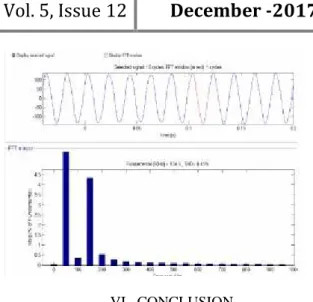
Amid remuneration, the framework streams is indicate sinusoidal waveform, with low aggregate consonant contortion (THD = 3.93%). At t = t2 , a three-stage adjusted load step change is created from 0.6 to 1.0 p.u. The remunerated framework streams stay sinusoidal in spite of the adjustment in the heap current greatness. At long last, at t = t3 , a solitary stage stack step change is presented in stage u from 1.0 to 1.3 p.u., which is equal to a 11% current irregularity. Of course on the heap side, an unbiased current moves through the impartial conductor (iLn ), however on the source side, no nonpartisan current is watched (isn ). Reenacted comes about demonstrate that the proposed control conspire adequately dispenses with unequal streams.
Moreover, Fig. 8 demonstrates that the dc-voltage stays stable all through the entire dynamic power channel task.
Fig. 6. Simulated waveforms of the proposed control scheme. (a) Phase to neutral source voltage. (b) Load
Fig. 7. THD of Voltage and curents
VI. CONCLUSION
Enhanced dynamic current sounds and a receptive power remuneration conspire for control circulation frameworks with age from inexhaustible sources has been proposed to enhance the present nature of the appropriation framework. Points of interest of the proposed conspire are identified with its effortlessness, displaying, and usage. The utilization of a prescient control calculation for the converter current circle enhanced to be a viable answer for dynamic power channel applications, enhancing current following ability, and transient reaction. Mimicked comes about have demonstrated that the proposed prescient control calculation is a decent contrasting option to traditional straight control techniques. The prescient current control calculation is a steady and strong arrangement. Add up to symphonious contortion was lessened by utilizing fuzzy controller when contrasted with PI controller. Mimicked comes about have demonstrated the remuneration adequacy of the proposed dynamic power channel.
REFERENCES
[1]Pablo Acu˜na, Member, IEEE, Luis Mor´an, Fellow, IEEE, Marco Rivera, Member, IEEE, Juan Dixon, Senior Member, IEEE, and Jos´e Rodriguez, Fellow,
IEEE” Improved Active Power Filter Performance for
Renewable Power Generation Systems” IEEE TRANSACTIONS ON POWER ELECTRONICS, VOL. 29, NO. 2, FEBRUARY 2014 687
[2] J. Rocabert, A. Luna, F. Blaabjerg, and P. Rodriguez, “Control of power converters in AC
microgrids,”IEEE Trans. Power Electron., vol. 27, no.
11, pp. 4734–4749, Nov. 2012.
[3] M. Aredes, J. Hafner, and K. Heumann, “Three -phase four-wire shunt active filter control strategies,”
IEEE Trans. Power Electron., vol. 12, no. 2, pp. 311–
318, Mar. 1997.
[4] S. Naidu and D. Fernandes, “Dynamic voltage
Gener. Transm. Distrib., IET, vol. 3, no. 5, pp. 437–
447, May 2009.
[5] N. Prabhakar and M. Mishra, “Dynamic hysteresis current control to minimize switching for three-phase four-leg VSI topology to compensate nonlinear load,”
IEEE Trans. Power Electron., vol. 25, no. 8, pp. 1935–
1942, Aug. 2010.
[6] V. Khadkikar, A. Chandra, and B. Singh, “Digital
signal processor implementation and performance evaluation of split capacitor, four-leg and three h-bridge-based three-phase four-wire shunt active filters,”
Power Electron., IET, vol. 4, no. 4, pp. 463–470, Apr. 2011.
[7] F. Wang, J. Duarte, and M. Hendrix, “Grid -interfacing converter systems with enhanced voltage quality for microgrid application;concept and
implementation,” IEEE Trans. Power Electron., vol.
26, no. 12, pp. 3501–3513, Dec. 2011.
[8] X.Wei, “Study ondigital pi control of current loop
in active power filter,” in Proc. 2010 Int. Conf. Electr.
Control Eng., Jun. 2010, pp. 4287–4290.
[9] R. de Araujo Ribeiro, C. de Azevedo, and R. de
Sousa, “A robust adaptive control strategy of active power filters for power-factor correction, harmonic
compensation, and balancing of nonlinear loads,”IEEE Trans. Power Electron., vol. 27, no. 2, pp. 718–730, Feb. 2012.
[10] J. Rodriguez, J. Pontt, C. Silva, P. Correa, P. Lezana, P. Cortes, andU. Ammann, “Predictive current
control of a voltage source inverter,” IEEE Trans. Ind. Electron., vol. 54, no. 1, pp. 495–503, Feb. 2007.
AUTHORS:
KONDAPALLI PAPARAO Currently working as a Asst. Professor , Department Of Electrical And Electronics Engineering, Kakinada Institute of Engineering and Technology, Kakinada, East Godavari,A.P. His interested areas are Electrical Machines and Power systems.
PITHANI SURESH, Currently working as a Asst. Professor , Department Of Electrical And Electronics Engineering, Kakinada Institute of Engineering and Technology, Kakinada, East Godavari,A.P. His interested areas are Power systems.
NAMMI SAGAR TEJA YADAV
Currently working as a Asst. Professor , Department Of Electrical And Electronics Engineering, University college of Engineering, JNTUK, Kakinada, East Godavari, A.P. His interested areas are Power electronics and drives