A Noval Converter For Integrated Wind
–
Pv Energy System
Devika1, D.Srilatha2,
1
PG Scholar;2Assoc. Prof. Dept. Of EEE, Prakasam Engineering College , JNTUK,India, [email protected]; [email protected]
Abstract
This paper proposes a novel dc/dc converter topology that interfaces the non-conventional energy sources. It consists of four power ports: two sources (namely solar and wind), one bidirectional storage port, and one isolated load port. The proposed four-port dc/dc converter is derived by simply adding two switches and two diodes to the traditional half-bridge topology. Zero-voltage switching is realized for all four main switches. This paper proposes a new
four-port-integrated dc/dc topology, which is suitable for various renewable energy harvesting applications. An application interfacing hybrid photovoltaic (PV) and wind sources, one bidirectional battery port, and an isolated output port is given as a design example. It can achieve maximum power-point tracking (MPPT) for both PV and wind power simultaneously or individually, while maintaining a regulated output voltage.
I. Introduction
As interest in renewable energy systems with various sources becomes greater than before, there is a supreme need for integrated power converters that are capable of interfacing, and concurrently, controlling several power terminals with low cost and compact structure. This paper proposes a new four-port-integrated dc/dc topology, which is suitable for various renewable energy harvesting applications. Three of the four ports can be tightly regulated by adjusting their independent duty-cycle values, while the fourth port is left unregulated to maintain the power balance for the system. Compared to the effort spent on the traditional two- port converter, less work has been done on the multiport converter Circuit analysis and design considerations are presented. Four-port dc/dc converter has bidirectional capability.
In this paper, an alternative multi-input rectifier structure is proposed for hybrid wind/solar energy systems. The proposed design is a fusion of the buck and SEPIC converters. The features of the proposed topology are: 1) the inherent nature of these two converters eliminates the need for separate input filters for PFC 2) it can support step up/down operations for each renewable source (can support wide ranges of PV and wind input); 3) MPPT can be realized for each source; 4) individual and simultaneous operation is supported. The circuit operating principles will be discussed in this paper.
Simulation results are provided to verify with the feasibility of the proposed system.
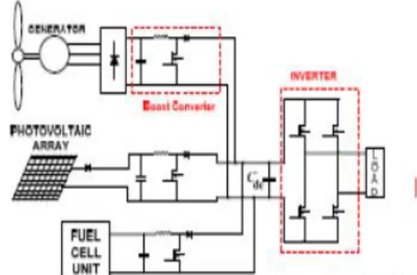
Fig 1: Hybrid system with multi-connected boost converter
II. Proposed Multi-Input Rectifier Stage
becomes a CUK converter and the input to output voltage relationship is given by (1). On the other hand, if only the PV source is available, then D2 turns off and D1 will always be on and the circuit becomes a buck converter as shown in Figure 4.The input to output voltage relationship is given by (2). In both cases, both converters have step-up/down capability, which provide more design flexibility in the system if duty ratio control is utilized to perform
MPPT control.
Fig 2: Proposed rectifier stage for a Hybrid wind/PV system
III. Analysis Of Proposed Circuit
To find an expression for the output DC bus voltage, Vdc, the volt-balance of the output inductor, L2, is examined according to Figure 6 with d2 >d1. Since the net change in the voltage of L2 is zero, applying volt-balance to L2 results in (3).The expression that relates the average output DC voltage(Vdc) to the capacitor voltages (vc1 and vc2) is
then obtained as shown in (4), where vc1and vc2can
then be obtained by applying volt-balance to L1and
L3. The final expression that relates the average output voltage and the two input sources (VW and VPV) is then given by (5). It is observed that Vdc is
simply the sum of the two output voltages of the Cuk and SEPIC converter. This further implies that Vdc
can be controlled by d1 and d2 individually or simultaneously.
= (
= (
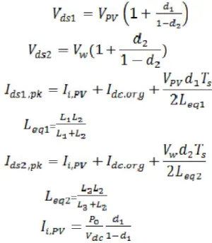
The switches voltage and current characteristics are also provided in this section. The voltage stress is given by equations respectively. As for the current stress, it is observed from Figure 6 that the peak
current always occurs at the end of the on-time of the MOSFET. Both the Cuk MOSFET current consists of both the input current and the capacitors(C1 or C2) current. The peak current stress of M1 and M2 are given by equations respectively. Leq1 and Leq2 represent the equivalent inductance of Cuk and CUK converter respectively.
=
=
IV. Mppt Control Of Proposed Circuit
A common inherent drawback of wind and PV systems is the intermittent nature of their energy sources. Wind energy is capable of supplying large amounts of power but its presence is highly unpredictable as it can be here one moment and gone in another. Solar energy is present throughout the day, but the solar irradiation levels vary due to sun intensity and unpredictable shadows cast by clouds, birds, trees, etc. These drawbacks tend to make these renewable system sinefficient. However, by incorporating maximum power point tracking
(MPPT) algorithms, the systems’ power transfer efficiency can be improved significantly. To describe
a wind turbine’s power characteristic, equation
describes the mechanical power that is generated by the wind.
and the pitch angle. The TSR, λ, refers to a ratio of
the turbine angular speed over the wind speed. The mathematical representation of the TSR is given by equation. The pitch angle, β, refers to the angle in
which the turbine blades are aligned with respect to its longitudinal axis.
λ=
Figure 3 are illustrations of a power coefficient
curveand power curve for a typical fixed pitch (β =0)
horizontal axis wind turbine. It can be seen from figure 3 that the power curves for each wind speed has a shape similar to that of the power coefficient curve. Because the TSR is a ratio between the turbine rotational speed and the wind speed, it follows that each wind speed would have a different corresponding optimal rotational speed that gives the optimal TSR. For each turbine there is an optimal TSR value that corresponds to a maximum value of the power coefficient(Cp, max) and therefore the maximum power. Therefore by controlling rotational speed, (by means of adjusting the electrical loading of the turbine generator) maximum powercan be obtained for different wind speeds.
Fig 3: Power Coefficient Curve for a typical wind turbine
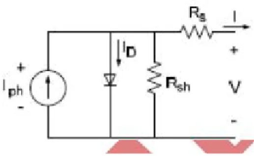
A solar cell is comprised of a P-N junction semiconductor that produces currents via the photovoltaic effect. PV array sare constructed by placing numerous solar cells connected in series and in parallel. A PV cell is a diode of a large-are forward bias with a photo voltage and the equivalent circuit is shown by Figure 4. The current-voltage characteristic of a solar cell is derived as follows:
I =
I =
-Fig 4: PV cell equivalent circuit
Typically, the shunt resistance (Rsh) is very large and the series resistance (Rs) is very small. Therefore, it is common to neglect these resistances in order to simplify the solar cell model. The resultant ideal voltage-current characteristic of a photovoltaic cell is given by and illustrated by Fig 5.
I =
-Fig 5: PV cell voltage-current characteristic
The MPPT scheme employed in this paper is a version of the HCS strategy. Figure 6 is the flow chart that illustrates the implemented MPPT scheme.
Fig 6: General MPPT Flow Chart for wind and PV
IV. Simulation Results
Fig7:Praposed Model
Fig.8:Control Scheme
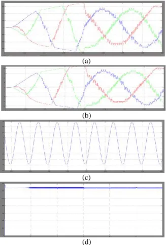
The out put voltages and currents are as shown in fig .
(a)
(b)
(c)
(d)
Fig.9 (a)load voltages (b) load currents (c)load current with fiter (d) battery voltage
Fig.10:Load current without filter %THD = 39.42%
VI. Conclusion
In the thesis load demand is met from the combination of PV array, wind turbine and the battery. An inverter is used to convert output from solar & wind systems into AC power output. Circuit Breaker is used to connect an additional load of 5 KW in the given time. This hybrid system is controlled to give maximum output power under all operating conditions to meet the load. Either wind or solar system is supported by the battery to meet the load. Also, simultaneous operation of wind and solar system is supported by battery for the same load.
References
[1] Joanne Hui*, AlirezaBakhshai, and Praveen K. Jain,“A Hybrid Wind-Solar Energy System: A New
Rectifier Stage Topology “, in Applied Power
Electronics Conference and Exposition (APEC), 2010 Twenty-Fifth Annual IEEE, pp 156-161, 21-25 Feb. 2010
[2] S.K. Kim, J.H Jeon, C.H. Cho, J.B. Ahn, and S.H.
Kwon, “Dynamic Modeling and Control of a Grid-Connected Hybrid Generation System with Versatile
Power Transfer,” IEEE Transactions on Industrial
Electronics, vol. 55, pp. 1677-1688, April 2008. [3] N. A. Ahmed, M. Miyatake, and A. K.
Al-Othman, “Power fluctuations suppression of stand-alone hybrid generation combining solar
photovoltaic/wind turbine and fuel cell systems,” in
Proc. Of Energy Conversion and Management, Vol. 49, pp. 2711-2719, October 2008.
[4] Wind and Solar Power Systems Design Analysis and Operation Second Edition, by Mukund R. Patel, Taylor & Francis Group Publishing Co.
[5] Y.M. Chen, Y.C. Liu, S.C. Hung, and C.S.
Cheng, “Multi-Input Inverter for Grid-Connected
Hybrid PV/Wind Power System,” IEEE Transactions
on Power Electronics, vol. 22, May 2007.
[6] S. Jain, and V. Agarwal, “An Integrated Hybrid
Power Supply for Distributed Generation Applications Fed by Nonconventional Energy
Sources,” IEEE Transactions on Energy Conversion,
vol. 23, June 2008.
[7] D. Das, R. Esmaili, L. Xu, D. Nichols, “An
Optimal Design of a Grid Connected Hybrid Wind/Photovoltaic/Fuel Cell System for Distributed
Energy Production,” in Proc. IEEE Industrial
Electronics Conference, pp. 2499-2504, Nov. 2005. [8] Dos Reis, F.S.,Tan, K. and Islam, S., “Using PFC
for harmonic mitigation in wind turbine energy
conversion systems” in Proc. of the IECON 2004
Conference, pp. 3100- 3105, Nov. 2004
[9] R. W. Erickson, “Some Topologies of High Quality Rectifiers” in the Proc. of the First International Conference on Energy, Power, and Motion Control, May 1997.
[10] D.S.L. Simonetti, J.Sebasti´an, and J.Uceda,