Report No. 430-2
September 2011
Complete:
Correct:
Consistent:
Verifiable:
Coordinate reference system • Geodetic datum
• Map Projection
• Numerically correct
• All conversions and transformations correctly executed • Terminology • Data model • Behaviour • Established integrity • Maintained integrity
Softw
are
revie
w
P
Global experience
The International Association of Oil & Gas Producers has access to a wealth of technical
knowledge and experience with its members operating around the world in many different
terrains. We collate and distil this valuable knowledge for the industry to use as guidelines
for good practice by individual members.
Consistent high quality database and guidelines
Our overall aim is to ensure a consistent approach to training, management and best
practice throughout the world.
The oil & gas exploration & production industry recognises the need to develop consistent
databases and records in certain fields. The OGP’s members are encouraged to use the
guidelines as a starting point for their operations or to supplement their own policies and
regulations which may apply locally.
Internationally recognised source of industry information
Many of our guidelines have been recognised and used by international authorities and
safety and environmental bodies. Requests come from governments and non-government
organisations around the world as well as from non-member companies.
Disclaimer
Whilst every effort has been made to ensure the accuracy of the information contained in this publication, neither the OGP nor any of its members past present or future warrants its accuracy or will, regardless of its or their negligence, assume liability for any foreseeable or unforeseeable use made thereof, which liability is hereby excluded. Consequently, such use is at the recipient’s own risk on the basis that any use by the recipient constitutes agreement to the terms of this disclaimer. The recipient is obliged to inform any subsequent recipient of such terms.
This document may provide guidance supplemental to the requirements of local legislation. Nothing herein, however, is intended to replace, amend, supersede or otherwise depart from such requirements. In the event of any conflict or contradiction between the provisions of this document and local legislation, applicable laws shall prevail.
Copyright notice
The contents of these pages are © The International Association of Oil & Gas Producers. Permission is given to reproduce this report in whole or in part provided (i) that the copyright of OGP and (ii) the source are acknowledged. All other rights are reserved.” Any other use requires the prior written permission of the OGP.
These Terms and Conditions shall be governed by and construed in accordance with the laws of England and Wales. Disputes arising here from shall be exclusively subject to the jurisdiction of the courts of England and Wales.
Part 2 – GIGS software review
Report No: 430-2
iv
©OGP
Table of contents
Preface vii
1 – Organisation of the GIGS software review checklist
1
2 – Filling out the software review checklist
3
3 – Elementary level
5
4 – GIGS Test Dataset
5
5.1
GIGS Test Series 0000 – Coordinates and their geodetic reference...7
5.2
GIGS Test Series 1000 – Documentation and Release Notes ...7
5.3
GIGS Test Series 2000 – Pre-defined Geodetic Parameter Library ...7
5 – Specific comments on the software review checklist
7
5.4
GIGS Test Series 3000 – User-defined Geodetic Parameter Library ...8
5.5
GIGS Test Series 4000 – User Interface ...8
5.6
GIGS Test Series 5000 – Data operations ...9
5.7
GIGS Test Series 6000 – Audit Trail ...10
5.8
GIGS Test Series 7000 – Deprecation ...10
5.9
GIGS Test Series 8000 – Error Trapping ...10
6.1
Coordinates and their Geodetic Reference (Series 0000) ...11
6 – Consolidation of evaluation results – GIGS grading
11
6.2
Documentation and Release Notes (Series 1000) ...14
6.3
Pre-defined Geodetic Parameter Library (Series 2000) ...16
6.4
User-defined Geodetic Parameter Library (Series 3000) ...17
6.5
User Interface (Series 4000)...19
6.6
Data Operations – Index sheet (Series 5000) ... 20
6.7
Data Operations (map projections) (Series 5100) ... 21
6.8
Data Operations (transformations and other conversions) (Series 5200) ... 23
6.9
Data Operations (2D seismic) (Series 5300) ... 24
6.10 Data Operations (3D seismic) (Series 5400) ... 27
6.11 Data Operations (Wells – Surface and Wellbore Deviation Data) (Series 5500) ... 30
6.12 Audit Trail (Series 6000) ... 34
6.13 Deprecation (Series 7000) ... 36
6.14 Error Trapping (Series 8000) ... 37
vi
©OGP
The purpose of this guidance note is to provide geoscience software developers and users with
recommended industry best practice to evaluate the capabilities of their software with respect
to establishing and maintaining geospatial data integrity. The guidance note is a response to
significant concern and user experiences of violations of geospatial integrity of data when using
geoscience software, leading to incorrect results, inconsistent understanding and misleading
information for the user community.
In 2008 this led to the formation of a joint industry project (JIP) sponsored by OGP to review
the situation and produce a series of recommendations, a supported set of standard test data, and
procedures for undertaking software review utilising that test data. OGP has taken the results
of this Geospatial Integrity of Geoscience Software (GIGS) JIP and incorporated them in this
guidance note which is in three parts:
1.
Part 1 – GIGS Guidelines
(OGP report № 430–1), describing the GIGS process;
2.
Part 2 – GIGS Software Review
(OGP report № 430–2, this document), containing a software
review checklist to enable structured testing of geoscience software; and
3.
Part 3 – User guide for the GIGS Test Dataset
(OGP report № 430–3).
This guidance note is supplemented by a number of companion electronic files:
•
Software review checklist
– an MS-Excel spreadsheet intended to facilitate the execution of a
geoscience software review and capture its results;
•
GIGS Test Dataset
– a series of data files to be used for testing of the algorithms and data
exchange capabilities of the geoscience software.
•
Sample MS PowerPoint slides
– explaining GIGS process and business benefits.
The above digital documents and files are available from the OGP Geomatics Committee website
–
http://info.ogp.org.uk/geomatics.
This document, 430–2, contains the text of the software review checklist; however, the evaluator is
strongly encouraged to make use of the MS-Excel spreadsheet provided for this purpose.
viii
©OGP
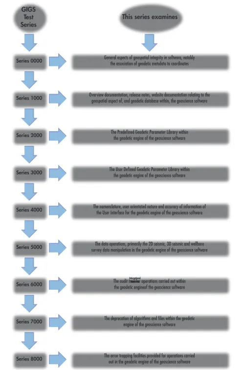
This software review checklist follows the grouping into Test Series as presented in OGP
Document 430 -1 ‘Geospatial Integrity of Geoscience Software – GIGS Guidelines’ and as shown
in figure 1 below.
Figure 1 – GIGS Test Series
International Standards
Series 0000 General aspects of geospatial integrity in software, notably the association of geodetic metsdata to coordinates
Overview documentation, release notes, website documentation relating to the geospatial aspect of, and geodetic database within, the geoscience software
The Predefined Geodetic Parameter Library within the geodetic engine of the geoscience software
The User Defined Geodetic Parameter Library within the geodetic engine of the geoscience software
The nomenclature, user orientated nature and accuracy of information of the User Interface for the geodetic engine of the geoscience software
The data operations, primarily the 2D seismic, 3D seismic and wellbore survey data manipulation in the geodetic engine of the geoscience software
The audit trail for operations carried out within the geodetic engineof the geoscience software
The deprecation of algorithms and files within the geodetic engine of the geoscience software
The error trapping facilities provided for operations carried out in the geodetic engine of the geoscience software
Series 1000 Series 2000 Series 3000 Series 4000 Series 5000 Series 6000 Series 7000 Series 8000 GIGS Test
Series This series examines
The description in this document focuses on the MS-Excel spreadsheet version of the check sheets.
Whereas this document contains a separate chapter for each Test Series, the spreadsheet version
contains a worksheet for each Test Series, intended to facilitate navigation.
For each Test Series sheet the actual Tests are preceded by a banner, indicating the subject of the
Test Series and, where relevant, a box containing notes, applicable to that Test Series.
1 – Organisation of the GIGS
software review checklist
2
©OGP
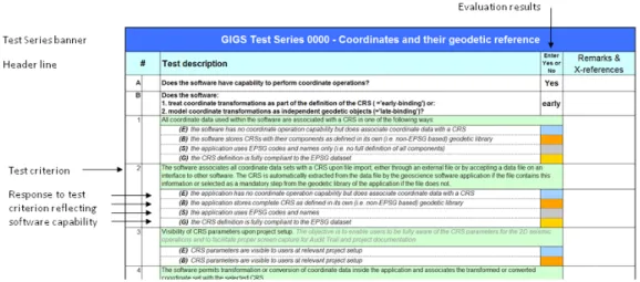
Figure 2 – Example of Checklist lay-outThe tests are numbered (1, 2,
…) and, where relevant, sub-numbered [ i), ii), ii),
…]; the first two
columns of the spreadsheets are reserved for this numbering. The test criterion is written in black
font against a pale green background. Italic text in dark grey has been added to some test criteria to
provide clarification of the test.
2 – Filling out the software review checklist
It is strongly recommended to use the MS-Excel spreadsheet version of the GIGS software review
checklist to conduct the software evaluation. However, software evaluators who do not wish
to do that can use the printed versions of the group of Test Series in this document. The main
advantages of the spreadsheet version are the overview it provides by using ‘worksheets’ or tabs,
and the automatic calculation of a summary score. Furthermore mistakes are less likely because
the spreadsheet contains (limited) functionality for checking the consistency of entries. Also
correction of mistakes is easier.
The evaluator should enter the response of the software to the test criterion into the column
marked in the header with the text “Enter Yes or No”. In the spreadsheet the fields in this column
will only permit a “Yes “or “No” as valid entry values. Some tests offer several possible responses,
reflecting the degree to which geoscience software may satisfy the test criterion. These reflect the
Bronze, Silver and Gold classification levels explained in Section 3.3 of OGP document 430–1,
Geospatial Integrity of Geoscience Software Part 1 – GIGS Guidelines
. The relevant fields are
colour-coded with a colour that symbolizes the classification level of the test; in addition the classification
level of each possible response is indicated by a letter in bold and in brackets:
(E)
: response for Elementary level
(B)
: response for Bronze level
(S)
: response for Silver Level
(G)
: response for Gold level
In a number of instances an informative question precedes the test:
(-)
:
informative question
Where multiple answers for a single test are provided in the checklist, software evaluators should
enter only one response per test, for the classification level that describes the applicable software
behaviour for that particular test. Compliance with lower level classification level is implied in any
of the levels. For example: if a Silver score is appropriate for a particular test, then fulfilment of the
requirements for the Bronze score is implied in the Silver score. If that is not the case, the software
evaluator should qualify the response in the “Remarks and Cross-references column”.
The last column of each Test Series worksheet allows the evaluator to record comments that
qualify or provide additional information on the test response. As space is limited in this column,
software evaluators may wish to create a separate file to record such information, entering
cross-references in this worksheet column.
4
©OGP
3 – Elementary level
Geospatial integrity is also very relevant for geoscience software that has no functionality to
perform coordinate conversions or coordinate transformations (collectively called coordinate
operations). To such software the classification levels Bronze, Silver and Gold are not relevant. Such
software can only attain the Elementary level of geospatial integrity. Software evaluators evaluating
this type of software should ensure that the answer to the question A in Test Series 0000: “Does
the software have capability to perform coordinate operations?” has been set to “NO”.
The test responses relevant for these software packages are indicated separately by an (E) preceding
the response text and a blue field in which to enter the response. For geoscience software that
has no functionality to perform coordinate operations,
do not fill in any of the (B), (S) or (G)
responses!
4 – GIGS Test Dataset
Software evaluators should use the GIGS Test Dataset to evaluate the geospatial capabilities of
their software numerically. OGP Document 430-3:
Geospatial Integrity of Geoscience Software
Part 3 – User Guide to the GIGS Test Dataset
contains a detailed description of each test to be
performed, included the expected outcome of each test. The tests in the GIGS Test Dataset are
grouped per Test Series, with each test having a unique number corresponding to the number of
the relevant Test Series. For example the tests in the GIGS Test Dataset, belonging to Test Series
5100 (Data Operations (map projections)) are numbered 5101 to 5113.
6
©OGP
5 – Specific comments on the
software review checklist
5.1 GIGS Test Series 0000 – Coordinates and their geodetic reference
The tests in this series address general aspects of geospatial integrity, specifically behaviour of the
software with respect to the association of coordinates with a valid CRS. The spatial data involved
includes seismic data and wellbore data but also extends to other spatial data.
In some questions the terms ‘unspecified CRS’, <null CRS> or ‘invalid CRS’ may be presented.
The first two terms refer to situations where no CRS information is associated at all with a spatial
data file, the latter to instances where incomplete or (partially) incorrect information on the CRS
is provided.
Test Series 0000 contains two preliminary questions A and B (see Figure 2 above), that have a
bearing on the entire check sheet and are crucial for the behaviour of the software with respect to
geospatial integrity:
Does the software have capability to perform coordinate operations?
and:
Does the software:
1.
treat coordinate transformations as part of the definition of the CRS (=‘early-binding’) or:
2.
model coordinate transformations as independent geodetic objects (=‘late-binding’)?
These must be answered.
5.2 GIGS Test Series 1000 – Documentation and Release Notes
The tests in this Series refer to the consistency and coverage of the overview documentation and
release notes of the software. Tests referring to specific subjects are grouped in the Test Series
relating to that subject.
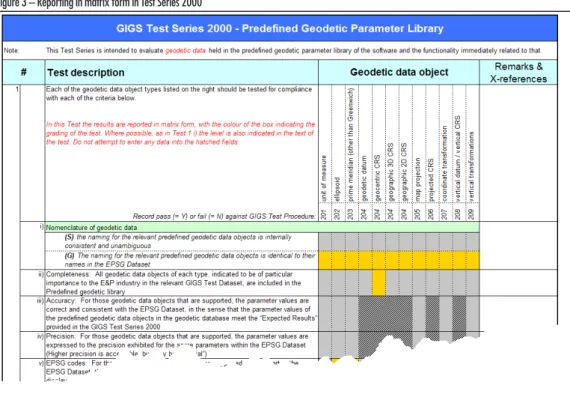
5.3 GIGS Test Series 2000 – Pre-defined Geodetic Parameter Library
This Test Series is intended to evaluate
geodetic data
held in the pre-defined geodetic parameter
library of the software and the functionality immediately related to that.
In Test 1 the results are reported in matrix form (see figure 3 below), whereby the colour of the
box indicates the ‘level’ to which the test refers. Where possible, as in Test 1 i), the level is also
indicated in the text of the test. No entry should be attempted in any of the hatched fields.
8
©OGP
Figure 3 – Reporting in matrix form in Test Series 20005.4 GIGS Test Series 3000 – User-defined Geodetic Parameter Library
This Test Series is intended to evaluate the
functionality
of the user-defined geodetic parameter
library of the software and the geodetic data that the user is able to create.
In analogy with Test Series 2000 the first test has to be reported in matrix form following the same
principles.
5.5 GIGS Test Series 4000 – User Interface
This Test Series contains a number of general tests regarding the user interface, which includes the
Graphical User Interface and any printed output. Most other user interface aspects are embedded
in the other Test Series, as they specifically apply to the subject matter of that Test Series.
5.6 GIGS Test Series 5000 – Data operations
This test series deals with software capabilities with respect to specific types of data, which is
frequently exchanged between software packages through industry standard data exchange
formats. In addition it assesses software capabilities with respect to coordinate operations,
i.e. support of algorithms for map projections, miscellaneous conversions and coordinate
transformations.
Each category of data or tests are grouped in separate worksheets and are separately numbered as
follows:
Series 5100
– Data operations (map projections)
Series 5200
– Data operations (coordinate transformations and miscellaneous conversions)
Series 5xxx
– Index sheet for Test Series 5300 - 5500
Series 5300
– Data operations (2D seismic)
Series 5400
– Data operations (3D seismic)
Series 5500
– Data operations (Surface and wellbore deviation data)
Test Series 5100 and 5200 address the capabilities of the software regarding coordinate operations.
The operation methods (algorithms) addressed in those Test Series and their grading reflect the
view of the original GIGS JIP Executive Committee on their relevance to the industry.
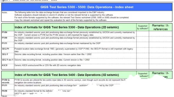
The Index sheet 5xxx is intended to record which data exchange formats are supported by the
software, given its functionality. The extent to which the software supports these formats should
not be recorded in the index sheet, except as a high level indication. The detailed behaviour of the
software with respect to these data exchange formats is evaluated in the Test Series 5300…5500.
For each of the formats supported by the software a separate sheet 5300…5500 should be filled out,
after copying the relevant worksheet (in the Excel version of the check sheet) or the relevant section
of this document.
Figure 4 – Index sheet for Test Series 5300 – 5500
The GIGS Test Dataset contains 2D seismic test data in P1/90 format and 3D seismic data (bin
grid definition) in P6/98 format. This does not preclude evaluation of the software’s support of
other formats and the software evaluator is encouraged to generate some test data for the other
supported formats.
10
©OGP
In the Test Series 5500 a distinction is made between a well track and a wellbore survey. Various
alternative terms are in use in the industry, but no standard exists and the terms proposed in these
Guidelines do not constitute a proposal for such standardisation. In the context of GIGS the
term
wellbore survey data
refers to the raw measurement data of Measured Depth (MD), azimuth,
inclination that have been gathered in a wellbore survey. The term
well track
refers to the collection
of coordinates of identified points along the wellbore, calculated from the wellbore survey data
using one of the algorithms in use in the industry, such as the minimum curvature method
1) or the
LMP method
2.
The GIGS Test Dataset contains test data in P7/2000 format, made available as an ASCII and an
MS-Excel file.
5.7 GIGS Test Series 6000 – Audit Trail
This Test Series works on the assumption that the software generates an audit trail. The audit trail
is populated by auxiliary metadata in respect of each data operation executed (i.e. create, import,
merge, and data processing through to transfer & export). When all requirements, expressed in the
tests below are satisfied, this contributes to the Gold scores of the software. If the software does not
log details of all coordinate operations, this does not block a possible Silver score of the software in
the summary result of the software review.
Some software may capture auxiliary metadata but not capture that in an audit trail. A number of
tests specifically address this scenario.
5.8 GIGS Test Series 7000 – Deprecation
This Test Series describes requirements for the deprecation of geodetic data objects. Since
deprecation is not yet an established aspect of the management of geodetic data objects in
geoscience software, all tests are graded at the Gold level.
5.9 GIGS Test Series 8000 – Error Trapping
All software will include some error trapping mechanisms. The error trapping tests described
in this Test Series aim to capture software behaviour regarding geospatial integrity. In the tests
distinction is made between the following software responses:
•
Warning flag (or message)
–
a message to the user informing him or her that geospatial integrity
may
be violated unless
preventive actions are taken
•
Error flag (or message)
–
a message to the user informing him or her that geospatial integrity
will
be violated; the
software allows the user to proceed
•
Strong error flag (or message)
–
a message to the user informing him or her of an imminent serious violation of geospatial
integrity; the software
blocks the intended action
.
1 See: Sawaryn, S.J., Tulceanu, M.A. A Compendium for Directional Calculations Based on the Minimum Curvature
Method: Part 2. Paper presented at the 2007 SPE Annual Technical Conference and Exhibition, Anaheim, California,
USA, 11-14 November 2007.
2 See: Zinn, N.D. Accounting for Earth Curvature in Directional Drilling. SPE paper 96813. Paper presented at the
2005 SPE Annual Technical Conference and Exhibition, Dallas, Texas, USA, 9-12 November 2005.
The supplied spreadsheet contains formulas that will automatically summarise the entries into
a consolidated result per Test Series. This is helpful in reporting the results of any structured
software reviews conducted with the GIGS methodology. The consolidated score for a given Test
Series is worked out as follows.
To obtain e.g. a Silver level score for a Test Series, all tests that list a Silver-graded response should
have a score of at least Silver, while all tests that only allow a Bronze-level response should have a
score at that Bronze level. If even one test acquires only a Bronze score where a Silver option was
listed, the overall score will revert to Bronze. If a Bronze-rated test response is missed, no GIGS
rating is achieved at all.
The above method of scoring demonstrates the progressive nature of the GIGS rating: A Silver
grade implies that all Bronze-rated requirements are met.
The consolidated score for any given Test Series therefore shows the minimum level at which the
software is rated. It is, in other words, not possible to compensate shortcomings on one aspect of
the software by superior results on other aspects.
The Elementary scores do not play a role in the evaluation of Bronze, Silver or Gold, as it applies
to an entirely different category of software, without coordinate operation capability. For such
software an Elementary grade can only be achieved if all tests containing a response for the
Elementary category have received a “Yes” entry.
The last worksheet in the evaluation spreadsheet shows a summary of the scores obtained from
each of the Test Series. It may be helpful in presenting the GIGS software review results in either
a report of presentation. The contents of the ‘Results’ column are automatically picked from the
original evaluation worksheet.
The person conducting the GIGS software review may have inserted additional worksheets for Test
Series 5300, 5400 and 5500, in order to evaluate the handling of additional data exchange formats
by the software. For such format evaluations an extra line may be created in the summary table of
this worksheet. This is left to the discretion of the evaluator.
The following sections give the evaluation spreadsheet contents in hard copy form for those who
prefer this to using the spreadsheet.
Whereas the software uses a yes/no box, this paper version requires a simple ‘tick’ for a yes and
blank for no.
6.1 Coordinates and their Geodetic Reference (Series 0000)
# Test description Tick if applicable Remarks & X-references
A Does the software have capability to perform coordinate operations? B If the answer to question A is “Yes”, does the software:
1. treat coordinate transformations as part of the definition of the CRS ( =’early-binding’) or: 2. model coordinate transformations as independent geodetic objects (=’late-binding’)?” 1 All coordinate data used within the software are associated with a CRS in one of the following ways
(E) the software has no coordinate operation capability but does associate coordinate data with a CRS ¨
(B) the software stores CRSs with their components as defined in its own (i.e. non-EPSG based) geodetic library ¨
(S) the software uses EPSG codes and names only (i.e. no full definition of all components) ¨
(G) the CRS definition is fully compliant to the EPSG dataset ¨
2 The software extracts the CRS from an imported data file or from the interface to other software; if CRS information is not available in the file or on the interface, it forces the user to select the CRS from its geodetic library
(E) the software has no coordinate operation capability but does associate coordinate data with a CRS ¨
(B) the software stores complete CRS as defined in its own (i.e. non-EPSG based) geodetic library ¨
(S) the software uses EPSG codes and names ¨
(G) the CRS definition is fully compliant to the EPSG dataset ¨
6 – Consolidation of evaluation results –
GIGS grading
12
©OGP
# Test description Tick if applicable Remarks & X-references
3 Visibility of CRS parameters upon project setup
The objective is to enable users to be fully aware of the CRS parameters for the 2D seismic operations and to facilitate proper screen capture for Audit Trail and project documentation”
(E) CRS parameters are visible to users at relevant project setup ¨
(B) CRS parameters are visible to users at relevant project setup ¨
4 The software permits transformation or conversion of coordinate data inside the software and associates the transformed or converted coordinate set with the selected CRS
(B) the software uses coordinate operation defintions from its internal non-EPSG library ¨
(S) the software uses coordinate operations from the EPSG dataset ¨
5 The software permits the CRS, associated with a coordinate dataset, to be changed by a user with sufficient user privileges, without transforming or converting the coordinates
(E) the software has no coordinate operation capability but allows the user to change the CRS associated with coordinate data ¨
(B) the software uses coordinate operations from the EPSG dataset ¨
6 The software automatically associates all coordinate data sets with their CRS upon file export
(E) the software has no coordinate operation capability but does associate coordinate data with their CRS ¨
(B) the software stores the CRS definiton as provided by the data source ¨
(S) the software uses EPSG codes and names ¨
(G) the CRS definition is fully compliant to the EPSG dataset ¨
7 The software prompts user to specify CRS upon file export
(E) the software has no coordinate operation capability but shows the user the CRS parameters exported with the data ¨
(B) the software only allows export of data in the CRS in which it is stored, but shows the user the CRS parameters of the data ¨
(S) the software prompts the use to specify a CRS for export and shows the user the associated geodetic paramters ¨
8 The software exports the CRS definition with the exported data file
(E) the software has no coordinate operation capability but exports the CRS defintion with the data ¨
(B) the software exports the CRS definition in a separate companion file with the exported data ¨
(S) the software exports the CRS definition, embedded with (i.e. in principle inseparable from) the exported data ¨
(G) the software exports the EPSG code of the CRS and/or CRS definition, embedded with (i.e. in principle inseparable from) the exported data ¨
9 The software responds to the user upon attempts to merge and/or co-visualise geodetically incompatiable data in one of the following ways
(-) the software supports merging of datasets ¨
(E) by prompting the user to specify the CRS ¨
(B) by blocking the import, merge or co-visualisation, issuing a warning message to the user ¨
(S) by prompting the user to select the CRS from its geodetic library ¨
10 Regarding merging/co-visualisation of geodetically incompatible data
(-) the software supports merging of datasets ¨
(E) the software blocks merging or co-visualisation of data referenced to different CRSs, or when one is unspecified (null) ¨
(B) the software blocks merging or co-visualisation of data referenced to different CRSs (including non-valid or unspecified CRS) but does not
automatically transform the data ¨
(S) the software automatically transforms or converts coordinates upon merge to a common valid CRS (usually the ‘project’ or ‘session’ CRS),
but will not transform/convert if one or more non-valid CRSs are involved. ¨
(G) the software validates the geodetic parameters of the CRS or transformation against the EPSG dataset and automatically transforms the
data when the CRS of the data to be imported is found to be valid. ¨
11 The software has additional features, offering a user help to identify the CRS of a geospatial dataset. The software will prevent a breach of geospatial integrity by e.g. not storing a dataset until it has been associated with a valid CRS
(G) it will allow merge or co-visualisation of spatial data where one of the data files has no CRS or an invalid, <null>, or unspecified CRS, but
prevents a breach of geospatial integrity (or equivalent advanced feature) ¨
12 Regarding the treatment of invalid or null CRS information, the software…
# Test description Tick if applicable Remarks & X-references
(S) …blocks merging or co-visualisation of spatial data where one of the CRSs is unspecified or a non-valid CRS ¨
13 The software has functionality to determine whether a CRS or a coordinate transformation is valid or not and…
(B) …matches the name to a name in its own geodetic parameter library (pre-defined plus user-defined) ¨
(S) …matches the CRS or transformation to an EPSG code and/or the EPSG name of the geodetic entity ¨
(G) …matches the parameters of the CRS or transformation to the corresponding benchmark EPSG parameters ¨
14 “Late-binding” configurations only: the software has functionality offering assistence to users which coordinate transformation to choose
This may be implemented in various ways, e.g. permitting defintion of one or more preferred transformations, by only offering coordinate transformations for selecting that are relevant for the area of the dataset extent or project area, etc.
(B) the software allows the user to select from a list, without supplying help re: the appropriateness of each transformation ¨
(G) the software has functionality, offering users assistence in the selection of the appropriate coordinate transformation. ¨
15 ”Late-binding” configurations only: as part of the selection process of the appropriate coordinate transformation the user can see the key characteristics of the coordinate transformation.
The key characteristics are considered to be: the EPSG code, the (full) EPSG name, the area of validity or a combination thereof. The values of the transformation parameters may help a skilled user to identify the coordinate transformation but is generally not sufficient as a selection criterion.
(S) the software displays EPSG/company codes and transformation parameter values ¨
(G) the software displays EPSG/company codes and the area of validity (and, possibly, the transformation parameters) ¨
16 Prior to merging or co-visualisation of two (or more) datasets…
(S) …the software transforms/converts the coordinate data if the CRSs of the datasets are different to a common CRS (usually the ‘project’ or
‘session’ CRS) ¨
17 “Early binding” configurations only: coordinate data belonging to two or more coordinate data sets with the same CRS, but associated with different coordinate transformations:
(G) will not be transformed upon to data merge or co-visualisation. ¨
18 Regarding units of measure, the software…
(S) …prevents users from freely selecting the unit of measure of the coordinates ¨
19 Regarding units of measure, the software…
(S) …allows different units of measure for vertical and horizontal coordinates within a project, as defined by the respective horizontal CRS
and vertical CRS ¨
20 Regarding units of measure, the software…
(S) …allows different units of measure for vertical and horizontal linear parameters within a project . Within a project, coordinate units of
measure for length may be different from the drilling units of measure for length. ¨
21 The ellipsoid is a component entity of the geodetic datum, which is in turn a component of the geodetic CRS
(S) the software prevents the selection of a CRS using the ellipsoid as the primary selection parameter ¨
22 Regarding transforming coordinate data upon export, the software…
(S) …permits the user to specify a different CRS for exported coordinate data and transforms or converts the coordinates prior to export. ¨
23 “Support of the two EPSG Dataset 7-parameter transformation methods (Position Vector 7-parameter transformation and Coordinate Frame Rotation transformation).
Appropriate user instruction on how to convert between these two methods is useful and should be documented if present.
(-) the software supports 7-parameter transformation methods ¨
(B) only one of the two methods is supported (the method is implied) ¨
(S) only one of the two methods is supported (method explicitly stated; users are clearly warned/advised on this) ¨
(G) both methods are explicitly named and supported; ¨
24 Definitions of coordinate transformations in the geoscience software…
(B) …are implicitly defined as “from <this CRS> to WGS 84” ¨
(S) …are explicitly defined as “from <this CRS> to WGS 84” ¨
(G) …are allowed to have any Source CRS and any Target CRS ¨
25 Help in selection of valid CRSs and/or coordinate transformations
(S) the software has functionality allowing identification of valid CRSs and/or coordinate transformations), based on textual description of the
Area of Use. ¨
(G) the software has functionality allowing identification of valid CRSs and/or coordinate transformations), based on spatial selection by
14
©OGP
6.2 Documentation and Release Notes (Series 1000)
# Test description Tick if applicable Remarks & X-references
1 i) The overview documentation…
(E) …provides a clear and accurate description of the purpose of the geoscience software ¨
(B) …provides a clear and accurate description of the purpose of the geoscience software ¨
ii) The overview documentation…
(E) …provides a clear and detailed description of coordinate handling in the geoscience software ¨
(B) …provides a clear and detailed description of coordinate handling in the geoscience software ¨
iii) The overview documentation provides a sufficiently detailed description of the geodetic data model used in the software
For example: “A projected CRS is built up of a base geographic CRS, a map projection and a coordinate system”, and “Coordinate transformation requires a source CRS and a target CRS”, “The following coordinate operation methods are used”
(B) at least 80% of the all geodetic object types in the test dataset are covered ¨
(S) all object types in test data set are covered ¨
(G) object types over and above those in test dataset are covered ¨
iv) The overview documentation provides lists of all coordinate operation methods supported by the software
This includes all supported map projection methods (such as Transverse Mercator, Albers Equal Area) and also coordinate transformation methods (such as 7-parameter position vector transformation method), etc.
(S) the overview documentation contains a list of all coordinate operation methods supported by the software. ¨
v) The overview documentation provides a list of data exchange formats supported
This refers in particular to the seismic and well data exchange formats mentioned in test series 5300, 5400 and 5500
(E) the overview documentation contains a list of all supported data exchange formats. ¨
(S) the overview documentation contains a list of all supported data exchange formats. ¨
vi) The overview documentation provides clear descriptions for troubleshooting the merging of datasets from, or export to, third party geoscience software applications
(E) the overview documentation provides instructions and help what such issues may be and how they are resolved. ¨ (S) the overview documentation provides instructions and help what such issues may be and how they are resolved. ¨
vii) Provides clear descriptions for troubleshooting the merging of datasets from, or export to, different versions of the same software
E.g. CRS of a dataset from a previous version was listed as UNKNOWN but in the new version, it is assigned by default the first CRS in the database “look up”; CRS of dataset was UNKNOWN and merged to another dataset with the same CRS assigned the correct name (but without proper transformation being performed, etc.
(E) the overview documentation provides instructions and help what such issues may be and how they are resolved. ¨
(B) the overview documentation provides instructions and help what such issues may be and how they are resolved. ¨
2 Nomenclature for geodetic data objects is consistent throughout the overview documentation in e.g. descriptions of the pre-defined geodetic parameter library, user-defined geodetic parameter library, data operations (including data import and data export)
(B) this nomenclature is internally consistent, possibly partly based on EPSG nomenclature ¨
(S) this nomenclature fully adheres to EPSG nomenclature ¨
3 Availability of overview documentation outside the software
(E) the overview documentation is available outside the software ¨
(B) the overview documentation is available outside the software ¨
4 Availability of the overview documentation or detailed help inside the software
(E) user documentation or detailed help is available for viewing within the software ¨
(B) user documentation or a general help file is available for viewing within the software ¨
(S) a searcheable, indexed help file is available inside within the software application ¨
(G) context-sensitive help is available to the user in any software window ¨
5 Table of Contents
(E) the overview documentation has a detailed table of contents ¨
# Test description Tick if applicable Remarks & X-references
6 Indexed content
(E) the overview documentation has a detailed index ¨
(B) the overview documentation has a detailed index ¨
7 The overview documentation - i.e both user documentation and any training documentation - of the geospatial functionality
(E) is updated with every major software version in which the geospatial functionality was modified ¨
(B) is updated with every major software version in which the geospatial functionality was modified ¨
8 Frequently Asked Questions (FAQ) section
(G) the overview documentation contains useful FAQs for the geodetic and geospatial functionality ¨
9 Version numbering
(E) overview documentation, release notes and software have consistent version numbers ¨
(B) overview documentation, release notes and software have consistent version numbers ¨
10 i) Release notes contain…
(S) …detailed and accurate information of updated geodetic database files ¨
ii) Release notes contain…
(S) …evidence and summary results of validation testing against a development test dataset ¨
iii) Release notes contain…
16
©OGP
6.3 Pre-defined Geodetic Parameter Library (Series 2000)
Note: This Test Series is intended to evaluate geodetic data held in the pre-defined geodetic parameter library of the software and the functionality immediately related to that.
# Test description Geodetics data object Remarks & x-Reference
1 Each of the geodetic data object types listed on the right should be tested for compliance with each of the criteria below.
In this Test the results are reported in matrix form, with the colour of the box indicating the grading of the test. Where possible, as in Test 1 i) the level is also indicated in the text of the test. Do not attempt to enter any data into the hatched fields.
unit of m ea su re ellip so id pri me me ridi an (o th er t ha n G ree nw ich ) ge od et ic d at um ge oc en tri c C RS ge ogr ap hic 3 D C RS ge ogr ap hic 2 D C RS ma p p roje ctio n proje cte d C RS co or din at e t ran sfor mat ion ve rti ca l d at um /v er tic al C RS ve rti ca l t ran sfor mat ion
Record pass (= Y) or fail (= N) against GIGS Test Procedure: 2001 2002 2003 2004 2004 0420 2004 2005 2006 2007 2008 2009
i) Nomenclature of geodetic data
(S) the naming for the relevant pre-defined geodetic data objects is internally consistent
and unambiguous ¨ ¨ ¨ ¨ ¨ ¨ ¨ ¨ ¨ ¨ ¨ ¨
(G) The naming for the relevant pre-defined geodetic data objects is identical to their
names in the EPSG Dataset ¨ ¨ ¨ ¨ ¨ ¨ ¨ ¨ ¨ ¨ ¨ ¨
ii) Completeness: All geodetic data objects of each type, indicated to be of particular importance to the E&P industry in the relevant GIGS Test Dataset, are included in the Pre-defined geodetic library
¨ ¨ ¨ ¨ ¨ ¨ ¨ ¨ ¨ ¨ ¨ ¨
iii)
Accuracy: For those geodetic data objects that are supported, the parameter values are correct and consistent with the EPSG Dataset, in the sense that the parameter values of the pre-defined geodetic data objects in the geodetic database meet the “Expected Results” provided in the GIGS Test Series 2000
¨ ¨ ¨ ¨ ¨ ¨
iv)
Precision: For those geodetic data objects that are supported, the parameter values are expressed to the precision exhibited for the same parameters within the EPSG Dataset (Higher precision is acceptable, but may be “artificial”)
¨ ¨ ¨ ¨ ¨ ¨
v) EPSG codes: For those geodetic data objects that are supported and are part of the EPSG Dataset, the correct EPSG codes are referenced and available to be seen in displays for the users
¨ ¨ ¨ ¨ ¨ ¨ ¨ ¨ ¨ ¨ ¨
vi)
Company codes: For relevant geodetic data objects supported, but which are not in the EPSG Dataset, specific company codes are clearly defined. (Company codes may also be used for items that are contained in the EPSG Dataset)
¨ ¨ ¨ ¨ ¨ ¨ ¨ ¨ ¨ ¨ ¨
# Test description Tick if applicable Remarks & X-references
2 The Pre-defined geodetic parameter library is read only:
(S) pre-defined geodetic data objects and parameters cannot be modified or deleted by any user ¨
3 The source of the geodetic data stored in the Pre-defined geodetic parameter library is:
(B) not or part-based on the EPSG dataset ¨
(S) the EPSG dataset ¨
4 Users can easily and promptly obtain the Version number of the EPSG Dataset used in the Pre-defined geodetic library either via online documentation or by contacting the vendor’s technical support.
(S) the Version number of the EPSG dataset is easily obtainable ¨
5 The user is able to update the Pre-defined geodetic library to a recent release of the EPSG Geodetic Parameter Dataset
(S) by replacement of the library file(S) with new file(S) as and when supplied by the vendor ¨
(G) by using functionality in the software to (semi)-automatically update its library contents with new EPSG dataset ¨
6 Users can view all the component geodetic data object details and parameter values for a given geodetic data object, based on selection of the principal geodetic data object
(S) all parameter values and components of geodetic data objects of pre-defined geodetic parameter library are visible to users through cursor control or drill-down menus
¨
7 User documentation on the pre-defined geodetic data objects is fully comprehensive, as described in Series 1000 GIGS Test Procedures; the documentation for the pre-defined geodetic parameter library is consistent with the overview documentation
6.4 User-defined Geodetic Parameter Library (Series 3000)
# Test description Geodetics data object Remarks & x-Reference
1 Each of the geodetic data object types listed on the right should be tested for compliance with each of the criteria below.
In this Test the results are reported in matrix form, with the colour of the box indicating the grading of the test. Where possible, as in Test 1 i) the level is also indicated in the text of the test. Do not attempt to enter any data into the hatched fields.
unit of m ea su re ellip so id pri me me ridi an ge od et ic d at um ge oc en tri c C RS ge ogr ap hic 3 D C RS ge ogr ap hic 2 D C RS ma p p roje ctio n proje cte d C RS co or din at e t ran sfor mat ion ve rti ca l d at um /v er tic al C RS ve rti ca l t ran sfor mat ion con cat en at ed tr an sfor mat ion
Record pass (= Y) or fail (= N) against GIGS Test Procedure: 3001 3002 3003 3004 3004 3004 3004 3005 3006 3007 3008 3009 3010
i) The software permits definition of the following new geodetic data objects ¨ ¨ ¨ ¨ ¨ ¨ ¨ ¨ ¨ ¨ ¨ ¨ ¨
ii) Units of Measure
(B) Units of defining parameters are implicit; the user is not free to select the unit
when creating the relevant User defined geodetic data object ¨ ¨ ¨ ¨ ¨ ¨ ¨ ¨ ¨ ¨
(S) The user is advised of any default and/or required units of measure assigned to
each specific defining parameter for user-defined geodetic data object creation ¨ ¨ ¨ ¨ ¨ ¨ ¨ ¨ ¨ ¨
iii) The facility for user-defined geodetic data object name is limited to less than the 80 characters allowed in the EPSG Dataset ¨ ¨ ¨ ¨ ¨ ¨ ¨ ¨ ¨ ¨ ¨ ¨ ¨
iv)
Precision allowed: Users are allowed to enter parameter values to the precision exhibited for corresponding parameters within the EPSG Dataset
See GIGS Test Dataset for specific examples
¨ ¨ ¨ ¨ ¨ ¨
v) The documentation provides guidance to users to assist them in creating the following User-defined geodetic data objects ¨ ¨ ¨ ¨ ¨ ¨ ¨ ¨ ¨ ¨ ¨ ¨ ¨
# Test description Tick if applicable Remarks & X-references
2 New geodetic entities can be composed in part from components available in the Pre-defined geodetic parameter library
(S) the software uses a proprietary data model ¨
(G) the software uses the ISO 19111 model (as used in the EPSG Dataset) ¨
3 The user is prompted by the software to make a selection or data entry for all mandatory components and attributes of the geodetic entity being defined.
The mandatory nature of geodetic entity components is specified in the ISO 19111 data model.”
(S) the software uses components in a proprietary data model ¨
(G) the software uses components as defined in the ISO 19111 model (as used in the EPSG Dataset) ¨
4 Creation of incompletely defined geodetic entities (for example as a result of not selecting a mandatory component of that geodetic entity):
(S) storage of incompletely defined geodetic entities is not possible ¨
5 User-defined geodetic data objects are differentiated from Pre-defined geodetic data objects and recognisable as such by the user. (G: codes; S: names)
(S) the software achieves this through the name or by other marker ¨
(G) the software uses codes for at least CRSs and, in the case of ‘late-binding’ soft coordinate transformations ¨
6 There is a facility to identify suitable geographic area of interest for user-defined geodetic data objects (CRS and coordinate transformation)
(S) the software uses a textual desciption of the area of validity ¨
(G) the software uses a graphic (map) interface to preselect or show valid geodetic data objects ¨
7 Geodetic data objects can be defined by:
(B) all users ¨
(S) only users with appropriate security levels ¨
8 Tidying up of the user-defined geodetic library:
(B) no user-defined geodetic entities are ever allowed to be deleted
(S) only users with sufficiently high security privileges can modify or delete non-associated geodetic data objects in the user-defined geodetic library
¨
9 The user-defined geodetic parameter library is secure from being updated (and thus lost) during a software update
18
©OGP
# Test description Tick if applicable Remarks & X-references
10 When a new CRS is created, the presentation of the axes (axes order, axes direction, axes name, axes abbreviation, default unit of measure) is clear and unambiguous, allowing no confusion as to meaning of any abbreviations used in one of the following three manners:
This is particularly important for projected CRS
(B) the presentation is implicit in the application’s user interface and in any exported data (= Bronze score) ¨
(S) the presentation is explicit in the application’s user interface and in any exported data (= Silver score) ¨
(G) the presentation fully complies with the EPSG Dataset definition of the coordinate system for similar CRS using the same conversion (map projection) method (= Gold score)
¨
11 User documentation on the User-defined geodetic data objects is fully comprehensive, as described in Series 1000 GIGS Test Procedures. The documentation for the User-defined geodetic parameter library is consistent with the overview documentation.
6.5 User Interface (Series 4000)
# Test description Tick if applicable Remarks & X-references
1 i) Ordering of latitude and longitude for geographic 2D CRS
(E) geographic 2D CRS coordinates are ordered: latitude, longitude (NOT longitude, latitude) ¨
(B) geographic 2D CRS coordinates are ordered: latitude, longitude (NOT longitude, latitude) ¨
ii) Ordering of latitude and longitude for geographic 3D CRS
(E) when supported, geographic 3D CRSs coordinate order is latitude, longitude, ellipsoidal height ¨
(B) when supported, geographic 3D CRS coordinates in order latitude, longitude, ellipsoidal height ¨
iii) For geographic coordinates (and other angular measures) the degree representation is clear and fully labelled [e.g. decimal degrees or symbol-separated sexagesimal form (123º45’57.891”N)]
(E) geographic coordinate values are explicitly labelled ¨
(B) geographic coordinate values are not labelled ¨
(S) degree representation are explicitly labelled ¨
(G) multiple degree representations are available, each of which are explicitly labelled ¨
iv) For projected CRSs, the coordinates are clearly defined and labelled and use the unambiguous terms ‘easting’ and ‘northing’for projected CRSs that are positive to the East and North
It is important to flag that abbreviations of ‘x’ and ‘y’ without a clear definition of which one is northing and which is easting are non-compliant and should be noted as such.
Such ‘x’ and ‘y’ abbreviations have completely opposite meanings (orientations) dependent on the specific projected CRS in use. In projected systems in standard use in about half the world, ‘x’ means northing and is the first coordinate in the coordinate tuple, and ‘y’ means easting and is the second coordinate in the coordinate tuple.
(E) x and y are fixed directions in the application for all projected CRSs or all coordinate values are explictly labelled ¨
(B) x and y are fixed directions for all projected CRSs; labelling is implicit ¨
(S) coordinates are defined unambiguously and explicitly labelled ¨
(G) coordinates are clearly defined and labelled and follow the coordinate axes order, axes abbreviations, axes names and axes orientations as stipulated in the EPSG Dataset for each specific projected CRS.
¨
2 i) Labelling of geodetic data objects is consistent in all dialog boxes/windows - for pre-defined & user-defined geodetic parameter library, data operations, data import and data export functions
(E) labelling is consistent across application, or, when incosistent, confusion is avoided by clear labelling ¨
(B) labelling is not consistent across application, but confusion is avoided by clear labelling ¨
(S) labelling is internally consistent across application but not following EPSG terminology ¨
(G) labelling is consistent and compliant with EPSG terminology ¨
ii) Key parameters for geodetic data object are visible to users through cursor control or sub menus in all relevant windows of the user Interface
This refers to Pre-defined & User-defined geodetic parameter library, Data Operations, Data Import and Data Export functions.
(B) display of key geodetic data object parameters are inconsistent across application, but confusion is avoided by clear labelling ¨
(S) display of key geodetic data object parameters are internally consistent across application but not following EPSG terminology ¨
(G) display of key geodetic data object parameters are compliant with EPSG terminology ¨
3 7-parameter transformation methods: users are clearly warned/advised which of the two EPSG Dataset 7-parameter transformation methods (Position Vector 7-parameter transformation and Coordinate Frame Rotation) method is used by the software
Appropriate user instruction on how to convert between these two methods is useful and if present should be noted in remarks.
(-) this question is applicable - the application supports one or both 7-parameter transformation methods ¨
(B) warnings on these transformation methods are implicit, mentioned in documentation ¨
(S) warnings on these transformation methods are explicit, mentioned in user interface and user documentation ¨
4 Consistency between user documentation and user interface
(E) the documentation at the user interface is consistent with the overview documentation ¨
20
©OGP
6.6 Data Operations – Index sheet (Series 5000)
Note: The following table lists the data exchange formats that are considered important to the E&P industry.
Software evaluators should indicate in column “”Supported by sotware”” whether or not the relevant format is supported by the software. For each of the formats supported by the software, the relevant Test Series worksheet (5300, 5400 or 5500) should be completed. Copy the relevant worksheet and repeat the evaluation for each of the formats supported by the software.
Index of formats for GIGS Test Series 5300 - Data Operations (2D seismic) Supported by software? Remarks & X-references
P1/84 An industry standard seismic post-plot positioning data exchange format previously established by UKOOA and currently maintained by the OGP. Current version is P1/90 but the P1/84 version is still important for legacy data
P1/90 An industry standard seismic post-plot positioning data exchange format previously established by UKOOA and currently maintained by the OGP
P1/11 An industry standard seismic post-plot positioning data exchange format maintained by the OGP
SEG-P1 post-plot location data exchange format 1983, (generally superseded by OGP P1/90); the SEG-P1 format is still important with legacy data SEG-Y Seismic data recording format, including position data. Version earlier than Rev 1 2002
SEG-Y
rev 1 Seismic data recording format, including position data. Current version is Rev 1 2002 ASCII Generic ASCII unstructured file or CSV file with 2D seismic navigation data
Index of formats for GIGS Test Series 5400 - Data Operations (3D seismic)
P1/90
Q-records P1/90 Q records are utilized for bin-centre input data in 3D seismic surveys, even though such records do not represent the final navigation bin-centre locations P1/11 An industry standard seismic post-plot positioning data exchange format published and maintained by the OGP
P6/98 An industry standard format for the definition of 3D seismic binning grids and the associated data exchange, previously established by UKOOA and currently maintained by the OGP
P6/11 An industry standard format for the definition of 3D seismic binning grids and the associated data exchange, (to be) published and maintained by the OGP; previous version is P6/98, revised in 2000
SEG-P1 post-plot location data exchange format 1983, (generally superseded by OGP P1/90); the SEG-P1 format is still important with legacy data SEG-Y Seismic data recording format, including position data; version earlier than Rev 1 2002
SEG-Y
rev 1 Seismic data recording format, including position data; current version is Rev 1 2002 SPS r & s
records SPS format - SEG Technical Standards Committee on Ancillary Data Formats, Shell Processing Support Format for Land 3-D Surveys, 2006; current version is SPS rev 2.1
Index of formats for GIGS Test Series 5500 - Data Operations (Surface and Wellbore Deviation Data)
P7/2000 An industry standard well deviation data exchange format previously established by UKOOA and currently maintained by the OGP; current version is Rev 5 - contains description of well curve data, through wellbore survey data (measured depth, inclination and azimuth) or calculated positions
P7/11 An industry standard well deviation data exchange format (to be) published and maintained by the OGP - contains description of well curve data, through wellbore survey data (measured depth, inclination and azimuth) or calculated positions
6.7 Data Operations (map projections) (Series 5100)
Note: This series is intended to capture the results of testing map projection functionality of the software, using the GIGS Test Dataset. Compliance can only be claimed if all sub tests of Test 1 pass and none of the tests 2, 3 or 4 fail.
For a Silver score Test 1 (all sub tests) must pass.
For a Gold score Test 1 (all sub tests) must pass, as well as the tests 2,3 or 4, when declared applicable to the software. No Bronze score is possible in this Test Series.
# Test description Tick if applicable Remarks & X-references
1 i) TM: Transverse Mercator conversion results
(-) method supported by application ¨
(S) pass against data in GIGS Test Procedure 5101 ¨
ii) LCC1: Lambert Conic Conformal (1 SP) conversion results
(-) method supported by application ¨
(S) pass against data in GIGS Test Procedure 5102 ¨
iii) LCC2: Lambert Conic Conformal (2 SP) conversion results:
(-) method supported by application ¨
(S) pass against data in GIGS Test Procedure 5103 ¨
iv) Stereo: Stereographic conversion results
(-) method supported by application ¨
(S) pass against data in GIGS Test Procedure 5104 ¨
v) OM-HotB: Oblique Mercator Hotine variant B conversion results
(-) method supported by application ¨
(S) pass against data in GIGS Test Procedure 5105 ¨
vi) OM-HotA: Oblique Mercator Hotine variant A conversion results
(-) method supported by application ¨
(S) pass against data in GIGS Test Procedure 5106 ¨
vii) Polyconic: American Polyconic conversion results
(-) method supported by application ¨
(S) pass against data in GIGS Test Procedure 5107 ¨
viii) Cassini: Cassini-Soldner conversion results
(-) method supported by application ¨
(S) pass against data in GIGS Test Procedure 5108 ¨
ix) Albers: Albers Equal Area conversion results
(-) method supported by application ¨
(S) pass against data in GIGS Test Procedure 5109 ¨
x) LAEA: Lambert Azimuthal Equal Area conversion results
(-) method supported by application ¨
(S) pass against data in GIGS Test Procedure 5110 ¨
xi) MercatorA: Mercator (variant A, 1SP) conversion results
(-) method supported by application ¨
(S) pass against data in GIGS Test Procedure 5111 ¨
xii) MercatorB: Mercator (variant B, 2SP) conversion results
(-) method supported by application ¨
(S) pass against data in GIGS Test Procedure 5112 ¨
xiii) TMSO: Transverse Mercator (South Orientated) conversion results
(-) method supported by application ¨
22
©OGP
# Test description Tick if applicable Remarks & X-references
2 For map projection methods additional to those listed above which are supported by application (list methods in remarks):
(-) the application supports methods in addition to those listed in Test 1 (if yes, please specify) ¨
(G) pass against independent test data ¨
3 If functionality is included in the software to compute grid convergence and scale factor
(-) the application contains functionality to compute grid convergence and, for conformal map projections, scale factor ¨
(G) evidence is supplied that these computations are correct ¨
4 If applicable to the application, azimuth reference…
(-) the application contains functionality for which azimuth reference is required ¨
6.8 Data Operations (transformations and other conversions) (Series 5200)
Note: This series is intended to capture the results of testing transformation functionality of the software, using the GIGS Test Dataset. Compliance can only be claimed if none of tests 1(i) through 1(viii), 2, 3(i) through 3(iii) or 4 fail.
No overall Bronze score is possible in this Test Series. For a Silver score Test 1 must pass.
For a Gold score: none of tests 1, 2, 3 or 4 fail and a pass is required for all of tests 1(i) through 1(viii) and 3(i) through 3(iii) and if 3D seismic data is supported by the application also test 2.
# Test description Tick if applicable Remarks & X-references
1 i) Geocentric translations between geographic 2D CRSs
(-) method is supported by application ¨
(S) pass against data in GIGS Test Procedure 5213 ¨
ii) PosVec: Position Vector transformations between geographic 2D CRSs
(-) method is supported by application ¨
(S) pass against data in GIGS Test Procedure 5203 ¨
iii) CoordFrame: Coordinate Frame Rotation transformations between geographic 2D CRSs
(-) method is supported by application ¨
(S) pass against data in GIGS Test Procedure 5204 ¨
iv) MolBad: Molodensky-Badekas transformations between geographic 2D CRSs
(-) method is supported by application ¨
(S) pass against data in GIGS Test Procedure 5205 ¨
v) NADCON: NADCON transformations between geographic 2D CRSs
(-) method is supported by application ¨
(S) pass against data in GIGS Test Procedure 5206 ¨
vi) NTv2: NTv2 transformations between geographic 2D CRSs
(-) method is supported by application ¨
(S) pass against data in GIGS Test Procedure 5207 ¨
vii) LonRot: Longitude Rotation transformations between geographic CRSs
(-) method is supported by application ¨
(S) pass against data in GIGS Test Procedure 5208 ¨
viii) VertOff: Vertical Offset transformations between vertical CRSs
(-) method is supported by application ¨
(S) pass against data in GIGS Test Procedure 5210 ¨
2 If the handling of 3D seismic bin grids is within the scope of the application: UKOOA P6 conversions
(-) handling of 3D seismic bin grid is within scope of application ¨
(S) pass against data in GIGS Test Procedure 5209 ¨
3 i) Geocentric translations between geocentric CRSs
(-) CRS types and/or method are supported by application ¨
(G) pass against data in GIGS Test Procedure 5211 ¨
ii) Geocentric translations between geographic 3D CRSs
(-) CRS types and/or method are supported by application ¨
(G) pass against data in GIGS Test Procedure 5212 ¨
iii) GeogGeocen: Conversion between geocentric and geographic 3D CRSs
(-) CRS types and/or method are supported by application ¨
(G) pass against data in GIGS Test Procedure 5201 ¨
4 For transformation methods additional to those listed above which are supported by application (list methods in remarks)
(-) CRS types and/or method are supported by application ¨