- Very low profile - typical height of 0.68mm - Low power loss, high efficiency
- Ideal for automated placement
- Halogen-free according to IEC 61249-2-21 definition
Molding compound, UL flammability classification rating 94V-0 Packing code with suffix "G" means green compound (halogen-free)
Terminal: Matte tin plated leads, solderable per JESD22-B102 Meet JESD 201 class 1A whisker test
SYMBOL UNIT
VRRM V
IF(AV) A
CJ pF
TJ °C
TSTG °C
Note 2: Measured at 1 MHz and Applied Reverse Voltage of 4.0 V D.C.
0.60 0.55 150 15 35 Typical junction capacitance (Note 2)
°C/W
Operating junction temperature range -55 to +150
Storage temperature range -55 to +150
Note 1: Pulse test with PW=300μs, 1% duty cycle Typical thermal resistance
RθJL RθJC RθJA
15 20 105
μA
mA Maximum reverse current @ rated VR
@ TJ=25 ℃ @ TJ=125 ℃
IR Maximum instantaneous forward voltage (Note 1)
@ 2.0A / TJ=25°C @ 2.0A / TJ=125°C
VF V
Maximum average forward rectified current 2
Peak forward surge current, 8.3 ms single half sine-wave
superimposed on rated load IFSM 25 A
Marking code D E F
Maximum repetitive peak reverse voltage 20 30 40
Weight: 0.006 g (approximately)
MAXIMUM RATINGS AND ELECTRICAL CHARACTERISTICS
(T
A=25
℃
unless otherwise noted)
PARAMETER SS22M SS23M SS24M
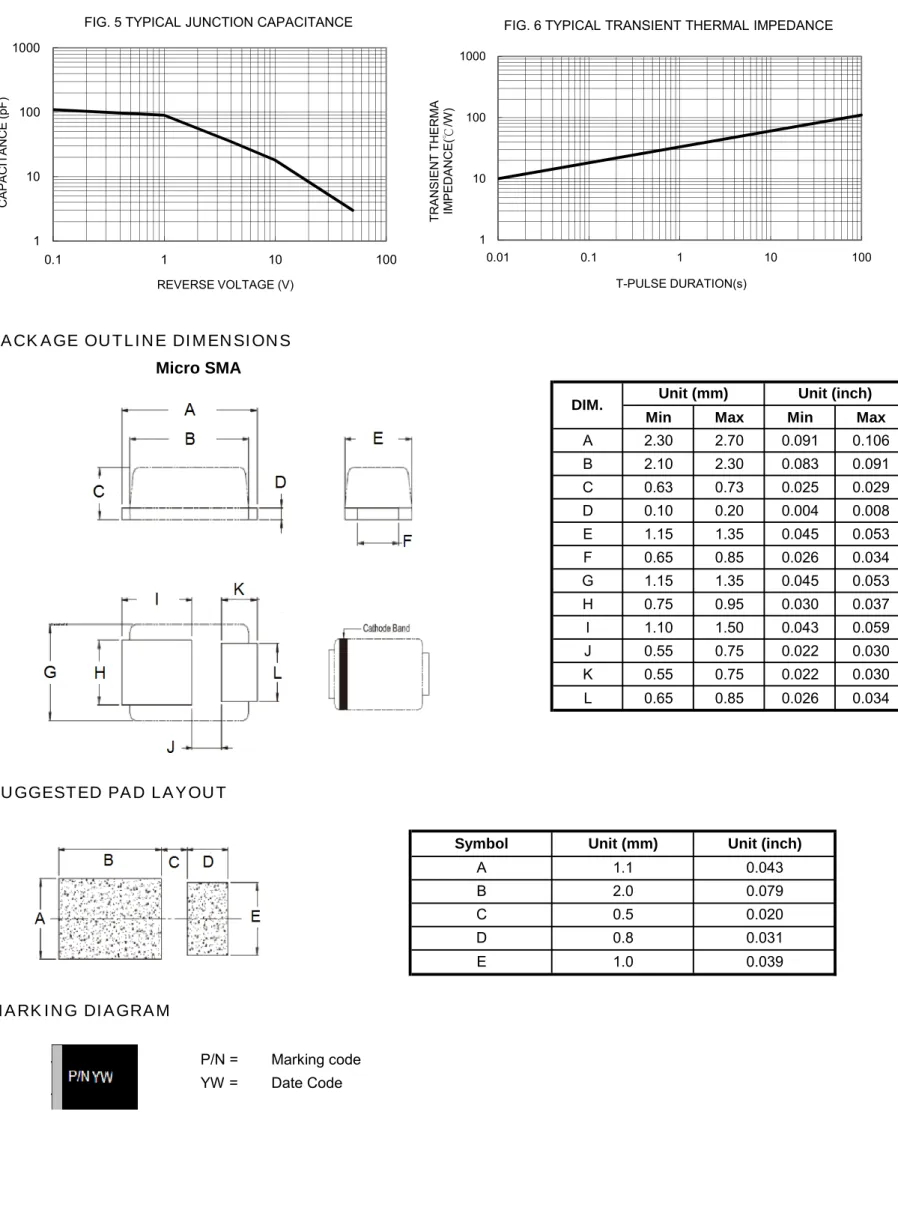
MECHANICAL DATA
Case: Micro SMA
Micro SMA
Polarity: Indicated bycathode band
Surface Mount Schottky Barrier
FEATURES
- Moisture sensitivity level: level 1, per J-STD-020 - Compliant to RoHS Directive 2011/65/EU and in accordance to WEEE 2002/96/EC
CREAT BY ART
PART NO.Note 1: "x" defines voltage from 20V (SS22M) to 40V (SS24M) Note 2: Whole series with green compound
PART NO.
SS24M
(TA=25℃ unless otherwise noted)
Document Number: DS_D1410055 Version: I14
SS22M thru SS24M
Taiwan Semiconductor
PACKING
ORDERING INFORMATION
EXAMPLE
3,000 / 7" Plastic reel
RS G Green compound
DESCRIPTION
PACKING CODE PACKING CODE
SUFFIX
PACKAGE
SS2xM
(Note 1, 2) RS G Micro SMA
PREFERRED
PART NO. PACKING CODE
PACKING CODE SUFFIX
SS24M RSG
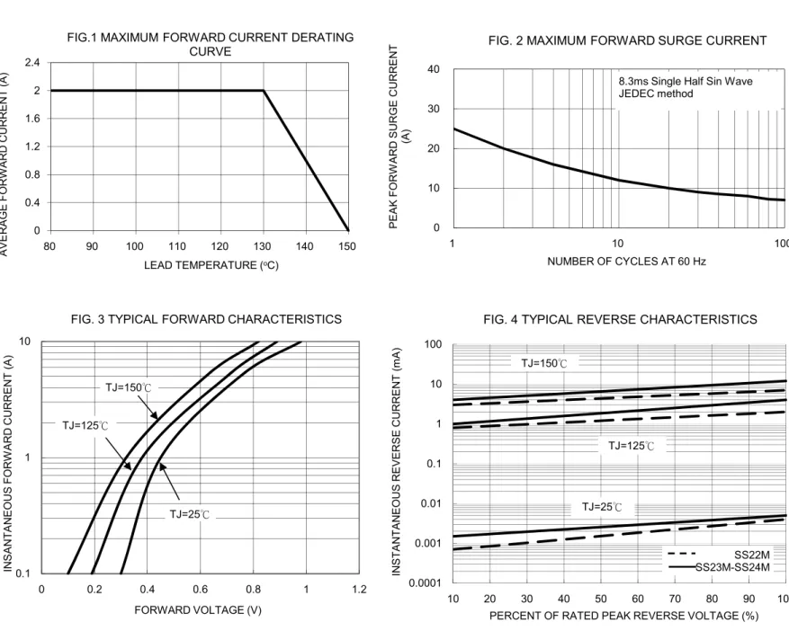
RATINGS AND CHARACTERISTICS CURVES
0 0.4 0.8 1.2 1.6 2 2.4
80 90 100 110 120 130 140 150
A V E R A G E F O RW A R D CURRE N T (A )
LEAD TEMPERATURE (oC)
FIG.1 MAXIMUM FORWARD CURRENT DERATING CURVE 0 10 20 30 40
1 10 100
P E A K F O RW ARD S U RGE CURRE NT (A )
NUMBER OF CYCLES AT 60 Hz
FIG. 2 MAXIMUM FORWARD SURGE CURRENT
8.3ms Single Half Sin Wave JEDEC method 0.0001 0.001 0.01 0.1 1 10 100
10 20 30 40 50 60 70 80 90 100
IN S T A N T A NE OUS RE V E RS E CURRE N T (m A )
PERCENT OF RATED PEAK REVERSE VOLTAGE (%)
FIG. 4 TYPICAL REVERSE CHARACTERISTICS
TJ=25℃ TJ=125℃ TJ=150℃ SS22M SS23M-SS24M 0.1 1 10
0 0.2 0.4 0.6 0.8 1 1.2
IN S A NT A N E O US F O RW A RD CURRE NT (A )
FORWARD VOLTAGE (V)
FIG. 3 TYPICAL FORWARD CHARACTERISTICS
TJ=150℃
TJ=125℃
Min Max Min Max
A 2.30 2.70 0.091 0.106
B 2.10 2.30 0.083 0.091
C 0.63 0.73 0.025 0.029
D 0.10 0.20 0.004 0.008
E 1.15 1.35 0.045 0.053
F 0.65 0.85 0.026 0.034
G 1.15 1.35 0.045 0.053
H 0.75 0.95 0.030 0.037
I 1.10 1.50 0.043 0.059
J 0.55 0.75 0.022 0.030
K 0.55 0.75 0.022 0.030
L 0.65 0.85 0.026 0.034
P/N = Marking code YW = Date Code
MARKING DIAGRAM
Unit (mm)
A 1.1
B 2.0
PACKAGE OUTLINE DIMENSIONS
DIM. Unit (mm) Unit (inch)
Micro SMA
SUGGESTED PAD LAYOUT
Symbol
C 0.5
D 0.8
E 1.0
Unit (inch)
0.043 0.079 0.020 0.031 0.039
1 10 100 1000
0.1 1 10 100
CA
P
A
CI
T
A
NCE
(pF
)
REVERSE VOLTAGE (V)
FIG. 5 TYPICAL JUNCTION CAPACITANCE
1 10 100 1000
0.01 0.1 1 10 100
TR
AN
SIEN
T TH
ER
M
A
IM
PED
AN
C
E
(
℃
/W
)
T-PULSE DURATION(s)
CREAT BY ART
assumes no responsibility or liability for any errors inaccuracies.
Information contained herein is intended to provide a product description only. No license, express or implied,to
any intellectual property rights is granted by this document. Except as provided in TSC's terms and conditions of
sale for such products, TSC assumes no liability whatsoever, and disclaims any express or implied warranty,
relating to sale and/or use of TSC products including liability or warranties relating to fitness for a particular purpose,
merchantability, or infringement of any patent, copyright, or other intellectual property right.
The products shown herein are not designed for use in medical, life-saving, or life-sustaining applications.
Customers using or seling these products for use in such applications do so at their own risk and agree to fully
indemnify TSC for any damages resulting from such improper use or sale.
Document Number: DS_D1410055 Version: I14