Sharif University of Technology
Scientia IranicaTransactions A: Civil Engineering www.scientiairanica.com
Research Note
Reliability-based evaluation of load factors using
unzipping and Bayesian methods
L.H. Naja, M. Tehranizadeh
*and M. Banazadeh
Department of Civil Engineering, Amirkabir University of Technology, Tehran, P.O. Box 15875-4413, Iran. Received 15 January 2011; received in revised form 11 August 2012; accepted 21 January 2013
KEYWORDS Seismic reliability; Bayesian method; -unzipping; Probabilistic design method;
Reinforced concrete frames;
PBEE.
Abstract.In this study, various sources of uncertainty in demand and capacity, and their direct and indirect dependencies according to their signicant function in Performance Based Earthquake Engineering (PBEE), were incorporated proposing a practically new simple procedure. This procedure distinguishes and evaluates the collapse probability of elementary mechanisms, as well as computes their dependencies, utilizing commonly used deterministic computer software through a full probabilistic methodology using -unzipping and Bayesian methods. This procedure has been benchmarked for a typical 2D reinforced concrete moment frame, and the reliability index of the structure for the most probable collapse mechanism was obtained within a reliability-based framework. Moreover, the coecients of dead, live and earthquake loads for a ACI load combination were reevaluated utilizing -unzipping and Bayesian methods through the proposed procedure, and were compared with the code's coecients. Good compatibility between obtained coecients and those of the code ones was perceived, and the probability of collapse, which was implicitly considered in the code, was revealed. It has been concluded that the coecients extracted from the Bayesian method are closer to those of the code compared to those from the -unzipping method. However, as it requires less primary computational eort and due to slight dierences between the results, -unzipping is usually more preferred by evaluators.
c
2013 Sharif University of Technology. All rights reserved.
1. Introduction
Modern constructions must satisfy seismic design cri-teria usually associated with the most adverse com-bination of occurrences with regard to building resis-tance under lateral loads. In order to assure safety requirements in the eld of seismic design, a reliability concept could be supportive [1]. It represents a relevant tool, which makes it possible to quantify the eects of uncertainties and to calculate the probability of failure, starting from the densities of probabilities associated *. Corresponding author. Tel: 00982164543030; Fax:
64543037
E-mail address: [email protected] (M. Tehranizadeh)
with random variables presented as input parame-ters [2-4]. Moreover, modern performance-based design codes are characterized by quantiable performance objectives gained by collaborating reliability concepts and evaluating uncertainties in ground motion, models and corresponding terms, structural responses, damage and important factors of design making [5,6].
The aim of this work is to propose a simple and practical new procedure for obtaining a system reliabil-ity index considering inherent uncertainties, also known as randomness, associated with design parameters, as well as types of uncertainty recognized as epistemic in terms of modeling uncertainties to evaluate coecients used in load combinations of the ACI318-08 code [7] for RC moment frames, without utilizing commonly used
uncertainty propagation modeling procedures, such as Monte Carlo or other computationally expensive actions [1].
With the help of the technique introduced in this study, an evaluator could segregate a model into simple parts and perform a reliability analysis for each part by a commonly used deterministic analyzing computer program, and, nally, integrate the parts.
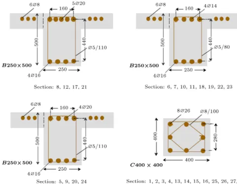
In this research, loading and design were done according to ASCE 7-05 [8] and ACI318-08 [7], re-spectively, and the included load combination is: 1.2D+L+E where any arbitrary load combination could be substituted. Material and loading details are illustrated in Tables 1, 2 and 3, and Figure 1 displays the designed sections.
2. Uncertainties in models and structural response variables
The issue of uncertainty in models and structural response variables, which is the main focus of this work, can be divided into three main categories:
- Design uncertainty: Accounts for possible options for elements and loads implemented in the design process aected by material characteristics and ge-ometric tolerances [1]. In this research, these un-certainties are considered consistent with the design code [7], both in demand and capacity parameters.
- Modeling uncertainty: Modeling the selected design pattern to the simple model representing the be-havior of a structure has its own uncertainties, as
strength and deformation may dier from expected values. It is always believed that the more rened the analytical model, the less modeling uncertainty is inserted into the design process. However, one could claim that the more complicated model, in terms of mathematical congurations, would need to have more input terms, which in turn could shed more ambiguity into the problem [9]. These uncertainties were incorporated into this research by the help of mean values attained through model evaluation and the amount of standard deviation gained by the help of moment-rotation close-form equations and standard deviations of materials, both in demand and capacity parameters.
- Human error and construction qualities: Although these sources of uncertainty are critical components in probabilistic assessment of the structural collapse capacity, they are out of the focus of the current study.
There is also another type of uncertainty which greatly aects the process of assessing structural seismic per-formance and should be considered prior to other uncertainties, which is the uncertainty in future ground motion, both in terms of intensity (obtained through the site specic hazard curve), frequency content and other attributes of ground motion (termed record-to-record variability) [9,10]. This type of uncertainty is considered for applied earthquake loads according to ASCE 7-05 [8] in this research. However, it is not classied in the discussed types of uncertainty because of its inherent dissimilarities.
Table 1. Mean values and standard deviations of material parameters [5].
[8]
Ec(N/m2) Concrete modules of elasticity 2.486E10 0.15
fc(N/m2) Specied concrete compression strength 2.758E07 0.15
ft (N/m2) Specied concrete tension strength 3.271E06 0.15
"c Specied concrete compression strain 2.220E03 0.15
"t Specied concrete tension strain 1.320E04 0.15
Es (N/m2) Steel modules of elasticity 2.001E11 0.1
fy (N/m2) Steel yield strength 3.449E08 0.1
Table 2. Mean values and standard deviations of loading parameters [5].
[8]
Dead load 4905 N/m2 4905*6=29430 N/m 29430 N/m 0.1
Live load 1962 N/m2 1962*6=11772 N/m 11772 N/m 0.334
Earthquake load R = 0:1, Wt= 784:8 N | |
Et 0.1*784.8=78.48 N 78.48 N 0.236
Table 3. Detail of loading.
D1; D3 (ton) D2; D4(ton) L1; L3 (ton) L2; L4 (ton) E1(ton) E2 (ton)
Figure 1. Designed sections according to ACI318-08.
3. Moment Frame system (MF)
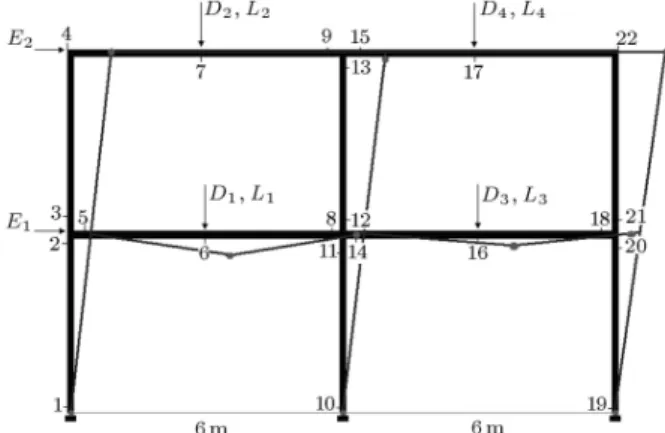
Moment frame systems are usually designed represent-ing a high degree of indeterminacy. As a result, when a structural system is undertaking a likely extreme loading situation, such as earthquake ground motion, collapse occurs only after constitution of an adequate number of component failures caused by plastic hinges with a exural mechanism. A well-designed ductile mo-ment frame comes into collapse mode when a sucient number of plastic hinges are formed. So, according to the number of points altering to the hinge and the number of required hinges for bringing out the frame to the mechanism situation, there could be diverse likely collapse paths, referred to as collapse mechanisms, and, due to dierent collapse mechanisms, dierent collapse probabilities could be attained for a moment frame [11]. For large frames, it is accommodating to system-atize the process of discriminating various potential failure mechanisms [12]. Thus, each collapse mecha-nism is taken apart into some cut sets of elementary collapse modes. This technique was implemented in this study, and for each elementary collapse mode of the system, reliability indexes were estimated. Later, based on the interaction of component failures, their con-tribution to the overall structural collapse and linear relations between contributed elementary mechanisms, the system's reliability index has been evaluated for any arbitrary collapse mechanism. Figure 2 displays the geometrical specications of the moment frame considered in this paper, the label of joints and the position of assigned loads.
Figure 2. Labels of joints and the place of loads assignments.
4. Approach of this research
The approach of this research could be claried briey as follows:
- The elementary collapse mechanisms of the frame were distinguished.
- The function equation (g-function) of each elemen-tary collapse mechanism was generated by discrim-inating the capacity-based and demand-based coef-cients and applying the power equality equation, Wext = Eint (the amounts of work based on external
and internal forces are in equilibrium condition).
- Knowing the function equation, the reliability index of each elementary mechanism was achieved. Then, the safety margin has been obtained in accordance
with the dierence between the capacity and demand of moments in the points altering to hinge.
- The dependency between these elementary
mecha-nisms was estimated by means of both -unzipping and Bayesian methods and the results were com-pared.
- The main collapse mechanism for the whole struc-ture was recognized, based on nonlinear static anal-ysis. (We could also reach this mechanism according to plastic analysis through the lower band theo-rem [12].)
- The collapse probability of the main mechanism
for the whole structure was evaluated utilizing -unzipping and Bayesian methods by the help of linear superposition between the contributed ele-mentary mechanisms in the main mechanism.
- At the nal step, the load coecients for the pre-sumed load combination were estimated and com-pared with the mentioned load coecients in the code [7].
In the following sections of this paper, each step of research, applied methods and comparison with commonly used previous methods were discussed and explained.
5. Elementary collapse mechanisms
Elementary collapse mechanisms are independent mechanisms that cause failure in some parts of the system and some of their linear superposition can lead to the overall collapse mechanism of the system. Distinguishing the elementary collapse mechanisms is an important stage of any research in the collapse assessment eld. A useful parameter in this eld is the reliability index, denoted as , which is calculated by the help of Eq. (1):
Pf = ( ); or 1 Pf = (); (1)
where:
Pf : The probability of collapse for the
referred mechanism.
() : The standard normal distribution
function
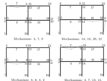
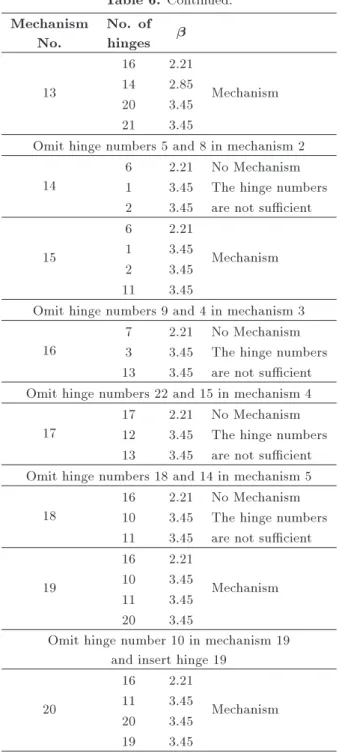
In some proposed methods for distinguishing elemen-tary mechanisms, like the method in [13], the reliability index or was calculated for each hinge, and the hinge with the minimum was selected as the rst hinge. So, the rst dominant elementary mechanism for the system could be distinguished when the number of required hinges was given [13]. In other words, we begin with a hinge including a minimum amount of and proceed to large ones up to conguration of a sucient number of hinges, constituting the mechanism condition. When the collaboration of all hinges was accomplished, all independent mechanisms of the frame were gained. This procedure, called a Heuristic technique, is frequently utilized for dis-criminating elementary mechanisms. The elementary mechanisms detected by this technique for the frame of our research are exposed in Table 4 from [5,13]. For more clarication, some of the mechanisms in this table are represented schematically in Figure 3. The mechanisms in Table 4 are not inclusive; therefore, three mechanisms of (1-2-6-11), (10-11-16-20) and (19-20-16-11) were adjoined by the authors to bring them to completion, then, the fullled mechanisms were illustrated in Table 5.
The procedure followed by the authors in the Heuristic technique was thoroughly presented in Ta-ble 6. The number of independent mechanisms gained by this step-by-step procedure is ten. As seen, this procedure is highly computational and time consuming
Figure 3. Schematic representation of some of the mechanisms in Table 4.
Table 4. Elementary mechanisms by heuristic technique [5,13]. (Joint labels are due to Figure 5.) Mechanism 4, 7, 9-15, 17, 22-14, 16, 18-14, 16, 21, 20-6, 8, 5-6, 8, 3, 2-4, 7, 15, 13
Table 5. Elementary mechanisms by Heuristic technique. (Reviewed and fullled by the authors. Joint labels are due to Figure 5).
Table 6. The approach of obtaining mechanisms for each hinge by the means of .
Mechanism No.
No. of hinges
1
6 2.21 No Mechanism 7 2.21
17 2.21 They are not in one span 16 2.21
Choose in one span 2
6 2.21
Mechanism 8 2.85
5 3.31 3
7 2.21
Mechanism 9 2.85
4 3.31 4
17 2.21
Mechanism 15 2.85
22 3.31 5
16 2.21
Mechanism 14 2.85
18 3.31
Omit hinge number 5 in mechanism 2 6
6 2.21 No Mechanism 8 2.85 The hinge numbers 3 3.45 are not sucient
7
6 2.21
Mechanism 8 2.85
3 3.45 2 3.45
Omit hinge number 4 in mechanism 3 8
7 2.21 No Mechanism 9 2.85 The hinge numbers 15 3.45 are not sucient
9
7 2.21
Mechanism 9 2.85
15 3.45 13 3.45
Omit hinge number 22 in mechanism 4 10
17 2.21 No Mechanism 15 2.85 The hinge numbers
9 2.85 are not sucient
11
17 2.21
Mechanism 15 2.85
9 2.85 13 3.45
Omit hinge number 18 in mechanism 5 12
16 2.21 No Mechanism 14 2.85 The hinge numbers 20 3.45 are not sucient
Table 6. Continued. Mechanism
No.
No. of
hinges
13
16 2.21
Mechanism 14 2.85
20 3.45 21 3.45
Omit hinge numbers 5 and 8 in mechanism 2 14
6 2.21 No Mechanism 1 3.45 The hinge numbers 2 3.45 are not sucient
15
6 2.21
Mechanism
1 3.45
2 3.45
11 3.45
Omit hinge numbers 9 and 4 in mechanism 3 16
7 2.21 No Mechanism 3 3.45 The hinge numbers 13 3.45 are not sucient Omit hinge numbers 22 and 15 in mechanism 4
17
17 2.21 No Mechanism 12 3.45 The hinge numbers 13 3.45 are not sucient Omit hinge numbers 18 and 14 in mechanism 5
18
16 2.21 No Mechanism 10 3.45 The hinge numbers 11 3.45 are not sucient 19
16 2.21
Mechanism 10 3.45
11 3.45 20 3.45
Omit hinge number 10 in mechanism 19 and insert hinge 19
20
16 2.21
Mechanism 11 3.45
20 3.45 19 3.45
As all hinges are contributed in mechanisms, other mechanisms are dependent to these mechanisms
for practical problems because of having to compute for all of the hinges. Moreover, achieved mechanisms do not have rational classication.
If we dene a mechanism that is leading to the partial failure of the system as a partial mechanism, in conformity with the denition in [12], then, noticing the elementary mechanisms in Table 5, it could be realized that all of them are partial mechanisms of the whole system, and their combination leads to the system's main collapse mechanism. In other words,
Figure 4. Example of getting arbitrary mechanism from elementary mechanism [4].
elementary mechanisms are partial mechanisms which are independent from each other. Therefore, elemen-tary mechanisms could be substituted by independent partial mechanisms of the frame and there is no need to perform the previous time consuming procedure to distinguish them. Partial mechanism detection, a typical practice in structural plastic analysis, is usually done by application of a cut-set concept (explained in the next part of this paper) and has been explained in several references related to this concept (e.g. [12]). Moreover, application of the Heuristic technique de-nes an elementary mechanism reecting capacity and demand terms at a member level. However, application of the cut-set concept denes elementary mechanisms by consideration of parameters at the system level [6]. To clarify the concept, it is useful to notice the simple model below. There are two elementary mechanisms for the frame in Figure 4, and other mechanisms could be obtained by superposing these elementary mechanisms [12]. At this point of the study, one is faced with the question of what the collapse mechanism of the whole structure is, and of which elementary mechanisms does it consist.
6. Distinguishing the minimum cut-sets
The minimum cut-set concept has been frequently used in methods of analyzing system reliability. One of these methods, which provides a compact, graphi-cal, intuitive representation, is the Fault Trees (FT) method [14] that was initially used by Bell Telephone Laboratories in connection with the safety analysis of the Minuteman missile launch control system in 1962 [15]. Fault tree models are failure space models describing events that cause system failure. The top event in a fault tree is any undesired event and its branches are the causes of this event. When applied to the eld of reliability, the top event is system failure, followed by all associated elements that could cause the top event to occur. Thus, the top event can be thought of as unreliability, or, in systems with repairable components, as unavailability. There are many methods to compute this top event probability. All of these methods use the probabilities of the causes or basic events and most of them are based on minimal cut sets.
Minimal cut-sets are the minimum combination of events such that, if operational, will cause system failure [16]. Minimal cut sets are equivalent to minimal paths of failure and completely dene system reliabil-ity [17]. Here, in our study, it could be said that the minimal cut sets for each failure mechanism are equivalent to the incorporated elementary mechanisms. In this study, probabilistic quantication of vul-nerability is attempted by means of an approach relying on First-Order Second-Moment (FOSM) ap-proximation of uncertainty. The basis of FOSM lies in the statement that satisfactory estimates of the parameters of a distribution (which may be unknown) may be given by rst-order approximations of Taylor series expansions of second-moment parameters (e.g. mean and variance) of a random variable calculated from samples. The FOSM framework addresses and processes uncertainties in input variables to provide estimates of the uncertainty in vulnerability of the system function equation [18].
In operational terms, FOSM analysis requires at least the denition of a central value and a measure of dispersion [19]. Here, the central value is considered as the mean value and the measure of dispersion as the variance of data. These values, in company with their distribution, is obtained from Tables 1 and 2 or from analyzing results, depending on their types, and is applied to the rst order approximation of the failure function in order to carry out the reliability analysis.
As the First-Order-Second-Moment (FOSM) method utilizes rst-order approximations of the vari-ables, it could be used precisely when the variation of bending moment between each two points is linear. Otherwise, FOSM can lead to inaccurate results in some cases, particularly when the modeling uncer-tainties cause a shift in the prediction of the median collapse point [10].
Frames typically fail after conguring a sucient number of plastic hinges in the most exposed cross sections and transforming the structure to a mechanism condition. For the frame in Figure 1, loading has been dened as concentrated loads ar some points; so, the variation of bending moment between each two points is linear, and distinguishing the bending critical points is simple. In a fully automated analysis, both end cross sections of each frame member and the points under
concentrated forces are considered as critical points (unless the end is connected to the joint by an internal hinge).
Solving the problem by hand calculations, we try to minimize the number of involved joints in elementary mechanisms. Provided that a joint connects only two members and is not subjected to an external moment (it is subjected to external forces only), it follows from the moment equation of equilibrium that the end moments are equal in magnitude (they have opposite hinges). In such a case, it suces to take into account only one of the end cross sections connected by the joint as a critical one. It must be emphasized that this simplication is not admissible for joints connecting three or more members [12]. Consequently, we could reduce the number of joints from twenty eight in Figure 2 to twenty two in Figure 5.
The number of independent partial mechanisms or elementary mechanisms of the system could be con-sidered as the minimal cut-sets or the minimum paths of failure that could be combined through logic gates, and-gates and or-gates. And-gates depict scenarios where all of the descendent events must occur for the event at the current level to occur; or-gates, on the other hand, depict scenarios where only one of the
Figure 5. The place of contributing plastic hinges.
descendent events needs to occur for the event at the current level to occur [16].
The number of independent partial mechanisms could be calculated by the following equation:
n = m s; (2)
where:
m : The number of points with a nonzero
amount of strain during plastic ow.
s : The number of independent
compatibility conditions.
n : The number of independent partial
mechanisms.
For a beam or frame, the amount of m is equal to the number of critical sections and s is equal to the degree of static redundancy of the structure [12]. Conse-quently, for the frame in Figure 5, ten independent par-tial mechanisms or elementary mechanisms have been detected (22-12=10). It should be pointed out that the numbers of elementary mechanisms are the same, either by the approach of Heuristic step-by-step or by consideration of partial mechanisms as elementary ones. For rectangular frames, elementary mechanisms are typically evaluated, so that each of them associates with one fundamental failure mode. Floor (horizontal) displacements are associated to panel mechanisms, joint rotations to joint mechanisms, and deections (vertical displacements) under concentrated forces are related to beam mechanisms [12]. Table 7 displays all elementary mechanisms of the frame achieved through the consideration of partial mechanisms.
7. Denition of component failure in terms of plastic hinge
In this work, beam and columns were modeled as elastic-with-hinge elements by the program SAP2000 (Structural Analysis Program). SAP and its family
Table 7. Specication of elementary mechanisms.
No of mechanism No of joints in mechanisms Category
1 3-4-13-12-22-21 Panel mechanism
2 1-2-11-10-20-19 Panel mechanism
3 4-7-9 Beam mechanism
4 15-17-22 Beam mechanism
5 5-6-8 Beam mechanism
6 14-16-18 Beam mechanism
7 2-3-5 Joint mechanism
8 9-15-13 Joint mechanism
9 8-12-11-14 Joint mechanism
software are packages from Computers and Structures, Inc. [20] developed for structural analysis and design. The SAP2000 package is a fully integrated system for modeling, analyzing, designing, and optimizing structures of a general type [21]. It enables conducting of the analysis and seismic design of buildings, oering various analyzing tools that vary from simple static 2D modeling to more complex nonlinear dynamic 3D modeling. Moreover, it responds to a large number of requirements in the eld of structural and nite element analysis and, in particular, for building design purposes. Since SAP could include many types of nonlinearity, according to the adjustment of analyz-ers like material nonlinearity, geometric nonlinearity, changes in structure, aging, creep, and shrinkage, and nonlinear reactions in some predened points (hinges), pushover analysis is one of its options that are largely used in the context of seismic design and diagnos-tic assessments [22-24]. Also, one may apply any arbitrary combination of load patterns, acceleration loads, and modal loads. Furthermore, the analysis can be done in either manner of load or displacement control [24].
In this study, hinge nonlinear and degradation characteristics were applied according to ASCE/SEI 41-06 [25], with no hardening ratio for the moment-rotation relation. The applied lateral seismic loads vary proportionally, according to a predened pattern con-sistent with ASCE 7-05 [8], in addition to consideration of P eects. Table 1 presents material specications for the elements. A full redistribution method was used for redistribution of forces in pushover analysis. The other assumptions are:
All the hinges are at the plateau state simultane-ously (at least, at some stage of the loading process). In other words, the plastic rotation in each hinge exists until the span or the whole frame comes to collapse or instability. Therefore, the sequence of hinge conguration in a mechanism does not have any importance.
The deformations must be suciently small prior
to collapse, unless we apply nonlinear modica-tion methods when handling the stiness matrix computation, where their application extensively complicates calculations, according to this study procedure.
8. Mechanism of failure for the whole structure and its minimum cut sets
After distinguishing the elementary mechanisms of the system, the mechanism of failure for the whole structure should be recognized in this step.
The moment frames, which are designed accord-ing to common codes, usually do not go beyond
redundancy in all possible degrees. However, the
main collapse mode is detected when the structure is pushed up to the point at which the structural lateral strength is dropped to 80% of its maximum value, (ductile collapse) or the system goes to instability (brittle collapse) [26]. For a frame with twelve degrees of redundancy, collapse happens when the 13th hinge is formed ideally. However, it is superlative for a designer to balance the strength and location of hinges in a frame to account for all hidden capacities of carrying extra forces due to indeterminacy. For a common design conforming to ordinary building code requirements (that is discussed in this paper), it could be said that this capacity is rarely gained.
For the frame of our research, by assuming that none of the hinges went to the fall-down portion of the moment-rotation diagram until the last hinge was created, the main mechanism of the frame could be obtained by pushover analysis of the model. For this purpose, the frame's lateral loading, which is consistent with the lateral loading pattern of the ASCE7-05 code [8], were amplied step by step, in a monotonically statistical procedure, until the frame reached collapse mode, which is dened as falling down to 80% of the maximum capacity of base shear or reaching instability condition [26].
Figure 6 represents the deformed shape in the main mechanism achieved by pushover analysis, caus-ing instability condition and the undeformed shape of the frame. The labels of contributed joints in the main mechanism are: (1-10-19-6-8-16-18-4-13-22), although they did not cover all redundancy degrees of the frame. The pushover curve of the building is presented in Figure 7.
More ductile design patterns should be chosen if one wants to attain the mechanism that covers all degrees of redundancy (ideal mechanism of collapse). However, since the adopted design in our work is a reg-ular code-compliant design, according to a frequently used code [7], the mechanism gained by nonlinear static
Figure 6. Deformation between mechanism situation and initial one.
Figure 7. Pushover curve of the building.
analysis could be considered the main mechanism of failure for the whole structure. It is ne to mention that the proposed approach in this study is a general approach, which can also be used for any arbitrary mechanism.
An important part of the research can be consid-ered the disjointing of the main failure mechanism to the minimum cut sets (elementary mechanisms). The main mechanism of the system could be obtained if elementary mechanisms are superposed as:
Mech No. 1+ Mech No. 2 - Mech No. 9- Mech No. 10 - Mech No. 7+ Mech No. 5+ Mech No. 6 = main mechanism of overall failure for the structure presented in Figure 6.
As analysis programs are not able to create sys-tem function equations in close-form, these equations were evaluated according to the threshold amount of moment in the nal step of the last hinge for each elementary mechanism. Also, since the sequence of hinge conguration does not have any importance in the mechanism, it is not dicult to gure out these equations directly by hand calculation, if the eects of normal and shear forces are overlooked. It must be mentioned that in this study, the eects of normal and shear forces were neglected only in the formation of the equilibrium equation for the mechanisms. However, these eects are incorporated in nonlinear analyses and computation of moments in the joints by the analyzing program.
8.1. Capacity-based coecients
Capacity-based coecients are used to represent mate-rial specications of the system, like fc, fsy, Es, Ec.
The mean and standard deviation of coecients are considered according to ACI318-08 [7], as many re-searchers recommend utilizing code-based capacity pa-rameters because of their mostly semi-empirical nature, blending mechanical considerations with experimental results [6]. These parameters have been presented in Table 1. ASCE 7-05 [8] considers extreme limit and lognormal distributions for some of these parameters, but, in this work, normal distribution has been used for all of them.
8.2. Demand-based coecients
Demand-based coecients are divided into two cate-gories:
(a) Loading coecients;
(b) System coecients.
Coecients of loading are associated with imported loads and displacements like dead, live and earthquake loads. Mean and standard deviation of these coe-cients are derived from ACI318-08 [7].
Coecients of the system associate with the moment (M) and rotation () in each hinge. The mean values of these parameters are equal to the amounts obtained from the analyses, and the standard deviations are estimated based on system equations for moment-rotation and standard deviations of incorpo-rated parameters in second order approximation. 9. Adjusting certain mechanism
In favor of calculating for each elementary mecha-nism, it is necessary to nd out its function equation. Since modeling and analyzing programs consider de-mand and capacity parameters deterministically, we should establish a technique to attain other collapse mechanisms, except the main mechanism by the pro-gram. To do so, it is primarily essential to adjust the pushover analysis to obtain a particular mechanism. In this part of the paper, the procedure followed by the authors to bring about a specic mechanism in the SAP program is explained.
In analyzing the system for the rst time, average amounts for all capacity parameters were assumed in all hinges. There are two approaches for constructing another mechanism with the help of the SAP program:
1. Consideration of over-strength amounts for other points that are not going to become hinge in a particular mechanism.
2. Consideration of under-strength amounts for points that are going to become hinge in a particular mechanism.
For instance, if the mechanism of (4-7-9) is going to be created in the system, one could enter over-strength capacity parameters for the other points in the system (more than mean values). Then, the other points will not become hinges, and the formation of hinges will tend to weaker points. Another approach is strength reduction in points that are going to become hinges to stimulate these points.
In the rst method, the probability of hinge formation is determined conditional to the probability of not becoming hinges at the other points. Therefore, it was estimated as being excessively overestimated. However, the absolute probability of hinge formation
could be attained by the second method. In the above case, the amount of for mechanism (4-7-9) by the rst method is 8.94, and by the second one is 4.85, which seems to be more realistic.
Application of second method has two diculties:
- The amount of reduction in strength properties is not initially denite and should be obtained by trial and error. Then, the minimum reduction of strength should be chosen for the more precise results.
- This method could not be used for mechanism recog-nition; another method should be utilized. In other words, the contributed points of each mechanism should be preliminarily detected and, after that, this method could be only applied for calculation. Since the large concentration of probability in normal distribution is in the domain of [ 8; 8], and the results inherit acceptable accuracy in this domain, we do not go beyond this domain in this paper.
10. Function equation (g-function)
The theoretical, time-invariant structural reliability problem is denoted by the integral:
p = Z
(x)
fX(x):dx; (3)
where p is the failure probability, fX(x) is the joint
Probability of Density Function (PDF) for a vector of random variables, X = [X1; X2; ; Xn]T representing
uncertain quantities, such as loads, material properties, constants and geometric dimensions, and (x) is the failure domain of the structure in the outcome space, x = [x1; x2; ; xn]T of X. For a general structural
system, the failure domain may be dened in the form of:
(x) [
k
\
i2Ck
fgi(x) 0g; (4)
where gi(x) denes the failure surface or limit-state
function of component i for i = 1; ; m, whereas a set of limit-state functions were formulated, so that fgi(x) 0g. In other words, when uncertain response
quantity exceeds a specied threshold, gi(x) takes
a negative value and failure is implied, m denotes the number of components, and Ck is the index set
for the kth cut set or elementary mechanism, where each cut set represents a minimal set of components, whose joint failure constitutes that cut set. The block model could be claried so that, whenever gi(x) is
considered an elementary mechanism, failures of the included components are series events happening one after another. However, when gi(x) is considered the
system's collapse mechanism, incorporated elementary mechanisms are parallel events [27,28].
If we consider each elementary collapse mech-anism by Zi, each Zi could be written as a linear
combination of Mjs contributing to that mechanism:
Zi= n
X
i=1
aijMj; (5)
Zi: Function equation for collapse
mechanism in step i,
Mj : Moment in hinge number, j.
The safety margin in this equation is the dierence of moments between the capacity and demand in the joints that will become hinges. Considering external forces, Eq. (5) could be expressed as Eq. (6):
Zi= q
X
p=1 n
X
j=1
ai;j;pMj;p q
X
p=1 m
X
k=1
bi;k;pQk;p; (6)
i : Number of step that the equation is
written for;
ai;jand bi;k are the coecients that would be attained
in step i by considering the equation of equilibrium, and are dierent for each Mj and Qk.
j : Number of points in the mechanism,
regardless of the point that Zk was
written for;
Mj : Amount of moments in the points of
the mechanism, regardless of the point that Zi was written for;
k : Number of loads contributed in a
certain mechanism;
Qk;p: Applied external load for span p in the
loading step of the linear system by index k;
Dead Load : Q1;
Live Load : Q2;
Earthquake Load :Q3;
p : Number of involved spans in the
mechanism.
The amounts of Qk;p were shown in Table 3. For
example, Q1;1, the dead load in span 1, is equal to
18 ton, or Q3;2, earthquake load in span 2, is equal to
(5:07=2) = 2:535 ton.
matrix form as follows:
Zi= [A]fXg; (7)
[X] =
M Q
; (8)
zi= [A]fXg; (9)
2
zi = [A][Cx][A]t; (10)
where:
zi: Matrix of average of x;
2
zi: Matrix of variance of x.
Therefore, we can dene as: i= Zi
Zi: (11)
Although calculation of ai and bj requires a
consider-able number of iterations for each mechanism, dening the function equation of the system as above has some advantages. The rst is simplication in stiness matrix production. The second, and more important, is the ability to acquire Zi as a linear function of
Mjs and Qks; subsequently, the First-order Second
Moment method could be precisely applied [13]. For clarication, the applied procedure will be explained in detail for the mechanism (14-16-18) in the next section.
11. Attaining safety margin equation
In this section, the applied procedure for generating the function equation or safety margin equation that was explained in the previous section has been described and thoroughly mentioned in a step by step procedure for the mechanism of (14-16-18) under the load pattern of 1:2D + L + E, and has been presented in Table 8. For the other mechanisms, the same procedure will be continued.
Procedure for attaining the safety margin equa-tion for the mechanism of (14-16-18):
1. Modeling the system, applying external forces, running the model and attaining the internal forces and moments in each point.
2. Transmitting forces and moments from other spans to the focused span; in this particular case, the
right-below span. By transmitting forces and
moments, one does not need to analyze the whole frame and it is adequate to analyze one simple frame with one story and one span. In the frame of our research, this action would be done automati-cally by the SAP program at each step. There are several methods to analyze a frame with one story and one span, like the method proposed in [29] or by utilizing the Portal Method.
It is necessary to explain that we assumed the
Table 8. ai;j;p and bi;k;pfor mechanism (14-16-18).
No of Steps
Step 1
a0;18;3 a0;14;3 a0;20;3
2.26
-1 0 0
b0;1;3 b0;2;3 b0;3;3
(L=8) = 0:75 (L=8) = 0:75 h = 4
Step 2
a1;18;3 a1;14;3 a1;20;3
3.79
-1 1.5 0.5
b1;1;3 b1;2;3 b1;3;3
1.2 1.2 -5.5
Step 3
a2;18;3 a2;14;3 a2;20;3
4.24
-1 1.5 1.5
b2;1;3 b2;2;3 b2;3;3
1.31 1.31 -6.3
Step 4
a3;18;3 a3;14;3 a3;20;3
4.85
-1 1.5 1.5
b3;1;3 b3;2;3 b3;3;3
1.44 1.44 -6.7
Load Pattern: 1:2D + L + E, Mechanism: 14-16-18, Span:3, P : 3 Q1;3= 1:2 (18 + 18) = 43:2 ton, Q2;3= (7:2 + 7:2) = 14:4 ton,
Q3;3= (2:92=2 + 5:07=2) = 3:995 ton
live load equal to 1.2 ton/m and the dead load equal to 3 ton/m or live load=(0.4) dead load. Then, the vertical load transmitted to a span in each step are divided as dead load=(1/1.4) vertical load and live load=(0.4/1.4) vertical load.
3. Step 0: The relation between the moment of the joint becoming hinge by the moments of 5 other joints and external forces transmitted to the span was extracted. By this step (Step 0), the equation of Zi in elastic mode and the amount of based on
Eq. (1) that is equal to 2.26 could be obtained at the end of step 0.
Step 0: = 2:26: (12)
4. Step 1: The pushover analysis was performed up to generation of the rst hinge, and the value of the moments and forces in all joints was extracted and transmitted to the focused frame. Also, up to date, values of Mjs and Qks have been estimated
and M14 has been replaced by Mp. Then, the
value of could be derived with the help of the modied stiness matrix utilizing the Unload Entire Structure method applied by the SAP program. This is the elastic reliability index of the system; the reliability in which the rst point of the system is going to be hinge and should be adapted to arrive at the plastic reliability index of the mechanism.
Step 1: = 3:79: (13)
5. Step 2: Now, we consider point 18 becoming a hinge while the consistency of hinge 14 is incorporated, and shear force equivalent to 0:5MP
L is added to the
shear at point 18. Therefore, we have:
Step 2: = 4:24: (14)
6. Step 3: Our model consists of two hinges in this step. To attain the equation in the third point, we should cover the consistency of both previous hinges and add shear equivalent toMP
L to both ends of our
beam. So, we have:
Step 3: = 4:85: (15)
This is assumed as the mechanism's . It should be mentioned once more that in modication of the stiness matrix, slight rotations in plastic hinges have been assumed, unless nonlinear modication methods should be implemented that could not be performed by hand calculations. For other mecha-nisms, a similar procedure was carried out and the amounts of aiand bjwere obtained. Distinguishing
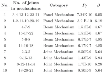
safety margin equations, the value of and the probability of collapse for each elementary mech-anism were executed and mentioned in Table 9.
Table 9. Safety index () and the probability of collapse (Pf) for elementary mechanisms without considering
mechanisms dependencies. No. No. of joints
in mechanisms Category Pf
1 3-4-13-12-22-21 Panel Mechanism 7.24E-10 6.05 2 1-2-11-10-20-19 Panel Mechanism 3.2 E-10 6.18 3 4-7-9 Beam Mechanism 1.51E-6 4.67 4 15-17-22 Beam Mechanism 1.51E-6 4.67 5 5-6-8 Beam Mechanism 6.17E-7 4.85 6 14-16-18 Beam Mechanism 6.17E-7 4.85 7 2-3-5 Joint Mechanism 8.50E-9 5.64 8 9-15-13 Joint Mechanism 1.43E-9 5.94 9 8-12-11-14 Joint Mechanism 1.7E-10 6.28 10 18-20-21 Joint Mechanism 8.50E-9 5.64
11.1. Calculating dependency between probabilities
Each collapse mechanism was represented by Zi, which
could be written as a linear equation of moments at the hinge points.
Zi= n
X
i=1
aiMi; (16)
Zk= n
X
i=1
biMi: (17)
Occurrence probabilities of dierent Zis are not
inde-pendent from each other. In some of them, similar Mis
participated. For instance, Mech (3-4-13-12-22-21) has a dependency on Mech (4-7-9) and (9-15-13) and some other mechanisms. This kind of dependency is called direct dependency. Moreover, there is also dependency among some Zis containing dissimilar hinges. For
instance, Mech (5-6-8) is dependent on Mech (8-12-14-11) and this mechanism is dependent on Mech (1-2-11-10-19-20). Therefore, Mech (5-6-8) is indirectly dependent on Mech (1-2-11-10-19-20), even though they have no similar hinges. For another example, occurrence of Mech (3-4-13-12-22-21) could decrease the probability of occurring other beam elementary mechanisms, like Mech (4-7-9) and (15-17-22), de-spite some similarities in their associated points, or P (Mech3jMech1) P (Mech3).
This type of dependency (named in this paper indirect dependency) has rarely been considered in pre-vious research, especially ones dealing with the values of for each hinge. However, getting the dependency matrix of various mechanisms by enhancement of the safety margin equation, as proposed in this research, is not intricate work, and indirect dependency is included using both -unzipping and Bayesian methods.
11.2. -unzipping method
The -unzipping method is a general strategy for estimating the failure probability of structural systems, initially proposed by Thoft-Christian and Murotso in 1986 [30]. This interactive, sequential, and iterative strategy relies upon the user to interpret and generate information about the system through the use of appro-priate techniques, such as directed experimental design, sampling techniques, response surface, and rst- or second-order reliability methods [31].
In the strategy, one tries to obtain increasingly accurate representations of the signicant failure re-gions and use these representations to arrive at an estimate of system failure probability. The goal is obtaining the probability of failure at the level of a hinge or elementary mechanisms, or for the whole
structure. These probabilities could be combined
through consideration of their dependencies and could be adjusted for obtaining the failure probability of the upper operational levels. For instance, by considering hinge failure probabilities and their dependencies, one could reach from the failure probability at a hinge level to the failure probability at an elementary mechanism level, and could continue until reaching the failure probability for the whole structure. As working with small numbers of probabilities is intricate and does not elucidate the accuracy level well, application of is substituted. Parameter could be calculated by Eq. (18) from the failure probability in each arbitrary system performance level. Eq. (18) is the repetition of Eq. (1), which is presented again in this part of the paper for better understanding. In addition, has geometrical interpretation, which reveals the distance from point (0,0) in the performance plane to the failure surface [32]. So, its application is more relevant than the failure probability for a specic system.
Pf= ( ); or 1 Pf = (); (18)
where:
Pf : The probability of collapse for the
studied mechanism;
() : The standard normal distribution
function.
In the -unzipping method, after modifying the probability of one mechanism based on the dependency of another, the probabilities of the other mechanisms must be also adapted according to this recent amount of probability, resulting in a great quantity of itera-tive calculations. However, the required calculations decrease greatly if indirect dependencies are ignored.
For instance, in our model, as there are seven elementary mechanisms contributing to the main mech-anism, forty two modications (7 (7 1) = 42) must be performed using the -unzipping method for com-prising indirect dependency between the mechanisms,
and, assuming symmetry in the dependency matrix, twenty one modications must be executed. In this situation, the number of modications could also be obtained by the number of possible choices of two from seven or (7!=(2! 5!) = 21). However, if the indirect dependencies were neglected, since only four mechanisms of theses seven mechanisms are dependent directly (4(4 1) = 12), twelve modications must be done, whereas, assuming symmetry in the dependency matrix, the number of calculations decreases to six. Performing these calculations without an analyzing program is too boring and time consuming. Thus, most researchers prefer to pass over indirect dependency, despite the fact that its consideration notably aects the accuracy of the results.
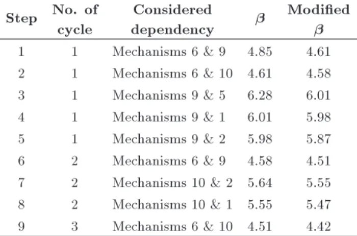
In this paper, a new practical strategy, following the -unzipping method, comprised of both direct and indirect dependencies, has been explained using an ordinary deterministic analyzing program, like SAP. For instance, modication of for mechanism No. 6 (14-16-18) was shown in Table 10 and described in a step by step procedure below:
Step 0: The probability of collapse for all individual mechanisms was revealed from the previous section. So, P (1); P (2); ; P (6); and P (9) have been available.
Step 1: Mechanism No. 1 was modeled, and corre-sponding internal forces and moments were obtained in the associated span in mechanism No. 6 by the help of the SAP program.
Step 2: The model was reset, and internal forces gained from step 1 were applied as additional external forces. Later, mechanism No. 6 was modeled, and the conditional probability of occurring mechanism No. 6, according to mechanism No. 1; (P (6j1)), was gained.
Table 10. Modication of for mechanism No.6 (14-16-18) including only direct dependency of mechanisms by -unzipping method.
Step No. of cycle
Considered
dependency
Modied 1 1 Mechanisms 6 & 9 4.85 4.61 2 1 Mechanisms 6 & 10 4.61 4.58 3 1 Mechanisms 9 & 5 6.28 6.01 4 1 Mechanisms 9 & 1 6.01 5.98 5 1 Mechanisms 9 & 2 5.98 5.87 6 2 Mechanisms 6 & 9 4.58 4.51 7 2 Mechanisms 10 & 2 5.64 5.55 8 2 Mechanisms 10 & 1 5.55 5.47 9 3 Mechanisms 6 & 10 4.51 4.42
Step 3: Calculation of P (6 \ 1) was done according to the equation of: P (6 \ 1) = P (6j1) P (1). Step 4: P (6 [ 1) was determined.
Step 5: The modied probability of mechanism No. 6 was calculated, according to: P (6)modied= P (6 [
1) P (1) + P (6 \ 1).
The occurrence probability of the other mechanisms should be adjusted according to this recent value of P (6)modied. The adjustment should be, thereby,
carried out based on the number of other collaborated mechanisms (in our model, 6 times). This procedure was also repeated for the other mechanisms. Con-sequently, 7 6 = 42 numbers of modication were nally done in iteration No. 1. Now, we can come back to mechanism No. 6 and do the modication over again, according to the recently achieved dependency values. This practice could be halted when permissible accuracy has been obtained. The probability of two mechanisms occurring simultaneously could be com-puted from the modied probability of each mechanism and their conditional occurrence probability, regarding symmetry in the dependency matrix, by the -unzipping method. This matrix can be seen in Figure 8. 11.3. Bayesian method
Bayesian Reliability presents modern methods and techniques for analyzing reliability data from a Bayesian perspective. The Bayesian approach treats the population of model parameters as random, not xed, quantities. In this method, old information or even subjective judgments are used to construct a prior distribution model for these parameters in
the rst step. This model expresses our starting
assessment about how likely various values of the un-known parameters are. Then, the current data of each parameter is used to revise this starting assessment via Baye's formula, deriving what is called a posterior distribution model for the model's population param-eters. Parameter estimates, along with condence intervals (known as credibility intervals), are calculated directly from the posterior distribution. Credibility intervals are legitimate probability statements about the unknown parameters, since these parameters are considered random, not xed.
In most applications, the probability distribution
of random variables is presumed in the rst step by the evaluators. So, modication could be done at each step, based on Bayes formula.
Bayes formula is a useful equation in probability theory that expresses the conditional probability of event A occurring, given that event B has occurred (written P (AjB)), in terms of unconditional probabil-ities, and the probability that event B has occurred, given that A has occurred. In other words, Baye's formula inverts which of the events is the conditioning event. The formula is:
P (AjB):P (B) = P (BjA):P (A); (19)
where P (B) in the denominator is further expanded by using the so-called \Law of Total Probability" to write:
P (B) =
n
X
i=1
P (BjAi):P (Ai); (20)
with events Ai being mutually exclusive, exhausting
all possibilities and including event A as one of the Ais [33].
The Bayesian method could precisely take ac-count of direct and indirect dependencies, since it comprises the indirect dependencies between all collab-orated and non-collabcollab-orated mechanisms in the main mechanism. In this research, the Hugin program was utilized for this purpose. As continuous variables could not be modeled in the Hugin program, Normal distribution modeling was carried out through 200 small discrete boundaries. The length of each boundary is considered equal to (8=100) and the credibility interval assumed for each variable is [ 8; 8]. Fig-ure 9 displays the probabilities of two simultaneous mechanisms in the Bayesian method with the help of the Hugin program, and Figure 10 demonstrates the Bayesian chart for the elementary mechanisms of the model.
Using the Bayesian method has some advantages. The rst is a release from performing time consuming and iterative calculations, and the second is the ability to stop the modication process at each desirable stage of calculation. Finally, one is able to contemplate indirect dependencies between mechanisms more pre-cisely. In the -unzipping method, it is not required to distinguish all elementary mechanisms and determine
Figure 9. Matrix of probabilities of 2 simultaneous elementary mechanisms Bayesian method.
Figure 10. Bayesian chart for moment and rotation mechanisms.
for each of them. It is sucient to evaluate only for elementary mechanisms collaborated in the system's main mechanism. However, in the Bayesian method, it is necessary to evaluate function equations for all elementary mechanisms. Then, calculation of and modeling in the Hugin program should be performed for all of them in order to comprise their indirect dependencies. As seen, obligatory prior calculations for the Bayesian method are more than for the -unzipping method. Calculation of dependency between elementary mechanisms is simpler, and an evaluator should choose between the methods in view of both prior and dependency calculations and the amount of acceptable accuracy. Most researchers, especially for complicated models, prefer to use the -unzipping method, although the -unzipping method is, frankly, not able to include the indirect dependencies between mechanisms collaborated in the main mechanism and in non-collaborated ones.
By the method proposed in this study (founded on achieving the occurrence probability of the main mech-anism in accordance with the occurrence probability of elementary mechanisms), utilizing the -unzipping method is more eortless than the previously used common procedures, based on the amount of in each hinge, and it is sucient for complicated models to distinguish the associated elementary mechanisms in the system's main mechanism and to compute their occurrence probabilities and dependencies. It requires less time, and dealing with elementary mechanisms is
more convenient than complicated mechanisms for the whole structure, according to each hinge's .
After modication of collapse probabilities in ac-cordance with the dependency between two simultane-ous elementary mechanisms, the safety index () values and the probability of collapse (Pf) have been obtained
by the two methods (-unzipping and Bayesian meth-ods). These values are expressed in Tables 11 and 12.
Table 11. Reliability index () and the probability of collapse (Pf) for elementary mechanisms considering
mechanism dependencies by -unzipping method. No. No. of joints
in mechanisms Category Pf
1 3-4-13-12-22-21 Panel Mechanism 4.65E-8 5.34 2 1-2-11-10-20-19 Panel Mechanism 5.35 E-9 5.72 3 4-7-9 Beam Mechanism 5.93E-6 4.38 4 15-17-22 Beam Mechanism 5.93E-6 4.38 5 5-6-8 Beam Mechanism 4.93E-6 4.42 6 14-16-18 Beam Mechanism 4.93E-6 4.42 7 2-3-5 Joint Mechanism 6.17E-7 4.85 8 9-15-13 Joint Mechanism 9.44E-8 5.21 9 8-12-11-14 Joint Mechanism 5.58E-7 4.87 10 18-20-21 Joint Mechanism 6.17E-7 4.85
Table 12. Reliability index () and the probability of collapse (Pf) for elementary mechanisms considering
mechanisms dependencies by Bayesian method. No. No. of joints
in mechanisms Category Pf
1 3-4-13-12-22-21 Panel Mechanism 2.33E-7 5.04 2 1-2-11-10-20-19 Panel Mechanism 1.79 E-8 5.51 3 4-7-9 Beam Mechanism 1.02E-5 4.26 4 15-17-22 Beam Mechanism 1.02E-5 4.26 5 5-6-8 Beam Mechanism 8.16E-6 4.31 6 14-16-18 Beam Mechanism 1.74E-5 4.14 7 2-3-5 Joint Mechanism 2.44E-6 4.57 8 9-15-13 Joint Mechanism 2.21E-7 5.05 9 8-12-11-14 Joint Mechanism 3.91E-6 4.47 10 18-20-21 Joint Mechanism 2.81E-6 4.54
12. Safety index for whole structure
The overall collapse probability of the structure could be obtained by the help of Eq. (21) and the gained collapse probabilities for each mechanism. Occurrence probabilities of three and more simultaneous mecha-nisms were ignored in this study.
P (A [ B [ C [ ) = P (A) + P (B) + P (C) + P (A \ B) P (A \ C) P (A \ D) + P (A \ B \ C) + P (A \ B \ D) +
P (A \ B \ C \ D) P (A \ B \ C \ E) + (21) The main failure mechanism of the whole structure presented in Figure 6 is identied by the superposition of: Mech No. 1+ Mech No. 2+ Mech No. 5+ Mech No. 6 - Mech No. 9- Mech No. 10 - Mech No. 7. Thus, the probability of collapse for a whole structure is equal to:
Pf(Mech1)+ Pf(Mech2)+ Pf(Mech9)
Pf(Mech7) Pf(Mech1&2)
Pf(Mech1&5) Pf(Mech1&6)
+ Pf(Mech9&1)+ Pf(Mech9&2)+ (22)
12.1. -unzipping method
P(failure of the whole system)= 9:91 10 6;
= 4:265:
12.2. Bayesian method
P(failure of the whole system)= 2:581 10 5;
= 4:048:
The probability of collapse from the -unzipping method is less than the probability of collapse from the Bayesian method. However, since the probabilities are very small, the dierences have little inuence on the reliability indexes of the whole structure and are very close to each other.
13. Results assessment according to Jcss probabilistic model code
Table 1 in part 7.2.1 of the Jcss Probabilistic Model Code [34] oers some quantities for . Our frame, as stated by that table, positioned in the class of buildings with moderate consequences of failure, and the cost of
safety measures for usual cases oered in this code, are equal to =4.2, which is too close to our obtained amounts of . Also, for investigation and comparison of obtained values by the values of the same system gained by the hinge-by-hinge procedure, one can refer to [13].
14. Evaluation of design parameters
One of the methods for considering probabilistic terms in the deterministic design process is application of some factors for design load combinations. In this research, the probability distributions for all loads are considered as Normal distribution and the achieved amounts of loads are considered their mean values. So, one could get the design combination factors by using Normal distribution if only the amounts of standard deviations are available.
The assumed load combination in this work is 1.2D+L+E, and standard deviations for loads that have been shown in Table 2 are equivalent to: DL =
0:1, LL = 0:334 and EL = 0:236. So, the standard
deviation for a load combination of (1:2D + L + E) is equal to: = (1:22 0:12+ 0:3342+ 0:2362)0:5 =
0:426. The coecients of loading were obtained with the help of values from the previous section, values of the mean and standard deviation for each of the applied loads and their combination and application of reliability analysis concepts.
The design coecients were obtained from the -unzipping method:
Rn 1:1878Dn+ 1:0343Ln+ 0:9878En: (23)
The design coecients were obtained from the Bayesian method:
Rn 1:1883Dn+ 1:0326Ln+ 0:9884En: (24)
The design coecients were obtained from code ACI318-08[7]
Rn 1:2Dn+ 1:0Ln+ 1:0En: (25)
It is seen that the load coecients are too close to each other from the two methods and also to the factors of the code [7]. This expresses that safety index () and the probability of collapse considered implicitly in the code [7] are close to the amounts of and the probability of collapse gained in our research by -unzipping and Bayesian methods.
15. Conclusions
- This research proposed a simple, practical method for obtaining the collapse probability of a structure from collapse probabilities of elementary mecha-nisms by means of a linear superposition principle utilizing common deterministic analysis software.
- The probability of collapse from the -unzipping method is less than the probability of collapse from the Bayesian method. This is because of more considered indirect conditional probabilities and more precise calculations in the Bayesian method. However, since the probabilities are very small, the dierences have little inuence on the reliability index of the whole structure. The reliability indexes of the whole structure obtained from -unzipping and Bayesian methods are equivalent to 4.265 and 4.087, respectively, while the probability of collapse of the Bayesian method is 2.83 times the collapse probability of the -unzipping method.
- It can be seen that the load factors (factors used in a design load combination) obtained by the procedure of this research are too close to the load factors in the ACI318-08 code [7]. For a live load, the most (percentage of error=3.3%) and for the dead load, the least (percentage of error=0.97%) dierences from the factors in the code [7] were obtained.
- Although the dissimilarities between estimated coef-cients from both -unzipping and Bayesian meth-ods by the code's load combination factors are small, it could be said that the Bayesian method results in more precise coecients than the -unzipping method. However, requiring less primary computa-tional charge and having a small value of dierences, -unzipping is frequently used for probabilistic de-signs.
- Extreme limit and lognormal distribution are usually used for earthquake and live loads, respectively, in most design codes, as well as in ACI318-08. Utilizing unlike distributions is one of the reasons for perceiving some dierences in terms of gained load factors, in this research, with factors in the
code [7]. Normal distribution was used in this
research for simplifying the calculation of standard deviation of the load combination. However, in order to achieve more precise live and earthquake load factors, corresponding distributions should be used for these loads. As extreme limit distribution has larger mean value and lognormal distribution smaller mean value than normal distribution, the obtained earthquake load factor obtained by normal distribution for earthquake load is less, and for live load, more than the amounts in the ACI318-08 code [7].
References
1. Ghoulbzouri, A. El, Khamlichi, A., Bezzazi, M. and Lopez-Almansa, F. \Seismic performance reliability analysis for reinforced concrete buildings", J. of Chem. Eng. and Constr. Tech., 2(3), pp. 45-53 (2011).
2. Hasofer, A.M. and Lind, N.C. \An exact and invariant
rst order reliability format", J. of Eng. Mech., ASCE, 100(12), pp. 111-121 (1974).
3. Ditlevsen, O. and Madsen, H.O., Structural Reliability Methods, Edn. John Wiley and Sons, pp. 75, New York, USA (1996).
4. Rackwitz, R. and Fiessler, B. \Structural reliability under combined random load sequences", Comput. and Struct., 9, pp. 489-494 (1979).
5. Barbato, M., Gu, Q. and Conte, J.P. \Response sensi-tivity and probabilistic response analysis of reinforced concrete frame structures", 8th U.S. Nat. Conf. on Earthq. Eng., San Francisco, California, USA, Paper No. 1872 (2006).
6. Jalayer, F., Franchin, P. and Pinto, P.E. \A scalar damage measure for seismic reliability analysis of RC frames", Earthq. Eng. and Struct. Dyn., 36, pp. 2059-2079 (2007).
7. ACI 318-08 \Building code requirements for structural concrete (ACI 318-08)", American Concrete Institute (2008).
8. ASCE \Minimum design loads for buildings and other structures", VA: ASCE 7-05, American Society of Civil Engineers, Reston (2002).
9. Liel, A., Haselton, C., Deierlein, G. and Baker, J. \As-sessing the seismic collapse risk of reinforced concrete frame structures, including the eects of modeling uncertainties", Special Workshop on Risk Acceptance and Risk Communication, Stanford University (2007).
10. Liel, A.B., Haselton, C.B., Deierlein, G.G. and Baker, J.W. \Incorporating modeling uncertainties in the as-sessment of seismic collapse risk of buildings", Struct. Saf., 31, pp. 197-211 (2009).
11. Toro, G.R. \Probabilistic analysis of combined dy-namic responses", Report 65, Department of Civil Engineering, Stanford University (1984).
12. Jirasek, M. and Bazant, Z.P., Inelastic Analysis of Structures, John Wiley & Sons, Ltd., 1st Edn., UK (2002).
13. Ranganathan, R. \Reliability analysis and design of structures", Indian Institute of Technology, McGraw-Hill, Bombay, India (1990).
14. Amari, S.V. and Akers, J.B. \Reliability analysis of large fault trees using the vesely failure rate", Annu. Rel. and Maint. Sym., pp. 391-396 (2004).
15. Rausand, M. and Hyland, A., System Reliability Theory; Models, Statistical Methods and Applications, 2nd Ed., John Wiley & Sons, New York, USA (2004).
16. Steeger G.M. \Reliability of systems using event oc-currence networks", Thesis No. 06-17, Department of The Air Force, Air University of Air Force Institute of Technology, Ohio (2006).
17. Haimes, Y.Y., Risk Modeling, Assessment, and Man-agement, John Wiley & Sons, New York, USA (2004).
18. Uzielli, M., Duzguny, S. and Vangelstenz, B.V. \A rst-order second-moment framework for probabilistic estimation of vulnerability to landslides", Int. Geo. haz. Eng. Confs., Lillehammer (2006).
19. Raviprakash, A.V., Prabu, B. and Alagumurthi, N. \Mean value rst order second moment analysis of buckling of axially loaded thin plates with random geometrical imperfections", Int. J. of Eng. Sci. and Tech., 2, pp. 150-162 (2010).
20. Computers and Structures, Inc., www.csiberkeley.com.
21. \CSI analysis reference manual for SAP2000, ETABS and SAFE", Berkeley, California, USA (2010).
22. Ghoulbzouri, A. El, Khamlichi, A., Bezzazi, M. and Lopez-Almansa, F. \Reliability analysis for seismic performance assessment of concrete reinforced build-ings", Aust. J. of Bas. and App. Sci., 3(4), pp. 4484-4489 (2009).
23. Hasan, R., Xu, L. and Grierson, D.E. \Push-over anal-ysis for performance-based seismic design", Comput. and Struct., 80, pp. 2483-2493 (2002).
24. Federal Emergency Management Agency \NEHRP guidelines for the seismic rehabilitation of buildings", Report FEMA 273, Washington, D.C. (1997).
25. ASCE \Seismic rehabilitation of existing buildings", ASCE/SEI 41-06, VA: American Society of Civil En-gineers, Reston (2007).
26. FEMA 356. \Prestandard and commentary for the seismic rehabilitation of buildings", Report FEMA-356, Washington, D.C., Prepared by the SAC Joint Venture for the Fed. Emerg. Manag. Agen. (2000).
27. James, T.P. Yao., Safety and Reliability of Existing Structures, Purdue University, Pitman Advance Pub-lishing Program, London, UK (1985).
28. Kiureghian, A.D. \Analysis of structural reliability under parameter uncertainties", Prob. Eng. Mech., 23, pp. 351-358 (2008).
29. Heae Norris, C., Benson Wilber, J. and Utku, S., El-ementary Structural Analysis, McGraw-Hill, 4th Edn., London, UK (1990).
30. Thoft-Christensen, P. and Murotsu, Y., Application of Structural System Reliability Theory, Springer-Verlag, USA (1986).
31. Ibrahim, Y. \General strategy for structural systems reliability analysis", J. of Struct. Eng., ASCE, 117(3), pp. 789-807 (1991).
32. Haldar, A. and Mahadevan, S., Probability, Reliability and Statistical Methods in Engineering, John Wiley and Sons, New York, USA (2000).
33. Engineering Statistics Handbook, NIST/SEMATECH e-Handbook of Statistical Methods, http://www.itl.nist.gov/div898/handbook/, April (2012).
34. Jcss Probabilistic Model Code, Joint Committee on Structural Safety, Published on the Internet, http://www.jcss.byg.dtu.dk/Probabilistic Model Code.aspx (2001).
Biographies
Leila Haj Naja obtained a BS degree in Civil Engi-neering from Sharif University of Technology, Tehran, Iran, in 2005, and is currently studying for her PhD degree in Earthquake Engineering at Amirkabir Uni-versity of Technology (Tehran Polytechnic), Iran. She has coauthored over 10 publications in related elds in conferences and journals. Her research interests include: structural reliability and risk evaluation. Mohsen Tehranizadeh was born in 1954, in Tehran, Iran. He received his BS degree in Structural Engi-neering from Sharif University of Technology, Tehran, in 1975, and MS and PhD degrees in Structural Engineering and Structural Dynamics in 1978 and 1986, respectively, from the University of Southern California, USA. He is currently Professor at the faculty of Amirkabir University of Technology, Tehran, Iran.
Mehdi Banazadeh received BS and MS degrees from the University of Tehran, Iran, and his PhD degree from the University of Ryukrus, Japan. He is currently Assistant Professor in the Department of Civil and Environmental Engineering at Amirkabir University of Technology, Tehran, Iran. His research interests include: nonlinear dynamic analysis, seismic design of concrete and steel structures and performance-based earthquake engineering.

![Figure 4. Example of getting arbitrary mechanism from elementary mechanism [4].](https://thumb-us.123doks.com/thumbv2/123dok_us/8394351.2230296/6.892.172.714.149.262/figure-example-getting-arbitrary-mechanism-elementary-mechanism.webp)