XEROX
4635/4635 MX
System
Program
Description
SST V3A Revision 8.0
Incremental V3A Revision 8.3
SYS UI SU.20.19 UI Dialog D.20.19 IOT 10.53 (level L)
May 18, 1995
a a a a a a a a a a a a a a a a a a a a a a a a a a a a a a a a a a a a a a a a a a a a a a a a a a a a a a a a a a a a a a a a a a a a a a a a a a a a a a a a a a a a a a a a a a a a a a a a a a a a a a a a a a a a a a a a a a a a a a a a a a a a a a a a a a a a a a a a a a a a a a a a a a a a a a a a a a a a a a a a a a a a a a a a a a a a a a a a a a a a a a a a a a a a a a a a a a a a a a a a a a a a a a a a a a a a a a a a a a a a a a a a a a a a a a a a a a a a a a a a a a a a a a a a a a a a a a a a a a a a a a a a a a a a a a a a a a a a a a a a a a a a a a a a a a a a a a a a a a a a a a a a a a a a a a a a a a a a a a a a a a a a a a a a a a a a a a a a a a a a a a a a a a a a a a a a a a a a a a a a a a a a a a a a a a a a a a a a a a a a a a a a a a a a a a a a a a a a a a a a a a a a a a a a a a a a a a a a a a a a a a a a a a a a a a a a a a a a a a a a a a a a a a a a a a a a a a a a a a a a a a a a a a a a a a a a a a a aXerox Corporation
101 Continental Boulevard
El Segundo, CA 90245
©1995 by Xerox Corporation. All rights reserved.
Copyright protection claimed includes all forms and
matters of copyrightable material and information
now allowed by statutory or judicial law or hereinafter
granted, including without limitation, material
generated from the software programs which are
displayed on the screen such as icons, screen displays
looks, etc.
Printed in the United States of America
Publication Number: 910920-11
Xerox© and all Xerox products mentioned in this
publication are trademarks of the Xerox Corporation.
Microsoft© the Microsoft logo, and MS-DOS© are
registered trademarks of Microsoft Corporation.
Changes, technical inaccuracies, and typographic
errors will be corrected in subsequent editions.
This Document was created on the Xerox 6085
Professional Computer System using VP software.
Reference Documentation
The following list of available Reference Documentation for the Xerox 4635 Laser Printing System has
been provided for your convenience. For other documentation information call the Xerox Documentation Subscription Service (XDSS) at 1-800-445-5554.
Title Publication #
Xerox Laser Printing Systems
4635 LPS Operator Guide 721P83010
Xerox Laser Printing Systems
4635 LPS Operations Reference 721P83020
Xerox Laser Printing Systems
4635 LPS Sysgen Guide 721P83030
Xerox Laser Printing Systems
4635 LPS Message Guide 721P83040
Xerox Laser Printing Systems
4635 LPS PDL/DJDE Reference 721P83050
Xerox Laser Printing Systems
4635 LPS Forms Creation Guide 721P83060
Xerox Laser Printing Systems
4635 LPS Product Reference 721P83070
Xerox Laser Printing Systems
4635 LPS Installation Planning Guide 721P83080
Xerox Laser Printing Systems
4635 LPS Operator Command Summary Card 721P83090
Xerox Laser Printing Systems
4635 LPS PC UI Reference 721P83100
Xerox Laser Printing Systems
4635 LPS Master Index 721P83110
Xerox Laser Printing Systems
LPS Font User Guide 600P86174
Xerox Laser Printing Systems
Program
Description
Catalog No. 910920-11
XEROX
4635/4635 MX
SYSTEM PROGRAM DESCRIPTION
May 1995
1.0 OVERVIEW . . . 1
2.0 PRODUCT OVERVIEW . . . 2
3.0 FEATURE DESCRIPTION . . . 3
3.1 OSS - Feature Description . . . 3
3.2 SYS UI - Feature Description . . . 8
3.3 UI DIALOG - Feature Description . . . 9
3.4 IOT - Feature Description . . . 11
4.0 HARDWARE CONFIGURATION/REQUIREMENTS . . . 13
4.1 4635 Base & Optional system configuration . . . 13
4.2 SYS UI . . . 14
4.3 IOT . . . 14
5.0 SOFTWARE RELEASE CONTENTS . . . 15
5.1 OSS - Release Contents . . . 15
5.2 SYS UI - Release Contents . . . 17
5.3 UI DIALOG - Release Contents . . . 19
5.4 IOT - Release Contents . . . 20
6.0 POINTS TO NOTE . . . 22
6.1 OSS - Points to note . . . 22
6.1.1 General . . . 22
6.1.1.1 Illegal or Corrupt Resources . . . 22
6.1.2 Software . . . 25
6.1.2.1 INPUT . . . 25
6.1.2.2 OUTPUT . . . 29
6.1.2.3 UTILITIES . . . 31
6.1.2.4 EXEC/SYSGEN . . . 36
6.1.2.5 Host Interface Processer (HIP) . . . 39
6.1.2.6 DIAGNOSTICS . . . 40
6.2 UI Dialog - points to note . . . 42
6.2.1 General . . . 42
6.2.2 Hardware . . . 42
6.2.3 Software . . . 42
6.3 SYS UI - points to note . . . 46
6.3.1 General . . . 46
6.3.2 Hardware . . . 46
6.3.3 Software . . . 46
6.3.3.6 Error Recovery . . . 47
6.4 IOT - points to note . . . .48
6.4.1 Hardware . . . .48
6.4.2 Software . . . .48
6.4.2.1 DUAL LAMP FUSER . . . .48
6.4.2.2 MICR . . . .48
6.4.2.3 Transparencies . . . .48
6.4.2.4 PC UI Display BarCode Sequence Mismatch . . . .48
6.4.2.5 Recovery Cleanup Loop . . . .48
7.0 KNOWN PROBLEMS . . . .49
7.1 OSS - Known Problems . . . .49
7.2 DIALOG - Known Problems . . . .51
7.3 SYS UI - Known Problems . . . .51
7.4 IOT - Known Problems . . . .52
8.0 PROBLEM FIXES IN THIS RELEASE. . . .54
8.1 OSS - Problem Fixes . . . .54
8.1.1 OSS - SPARs Fixed . . . .54
8.1.2 Change Request . . . .55
8.2 SYS UI Problem Fixes. . . .55
8.2.1 Other . . . .55
8.3 IOT - Problems Fixed . . . .56
8.3.1 IOT - SPARs Fixed. . . .56
8.3.2 Change Request . . . .56
9.0 XPSM/SDI Specific -Points to Note Information . . . .58
9.1 SDI (Shared Disk Interface) . . . .58
9.2 XPSM (Xerox Print Services Manager ) . . . .60
Appendix A SOFTWARE LOADING INSTRUCTIONS. . . .A-1 A1 OSS Software Loading Instructions . . . .A-1
A1.1 Sysgening the V3A R8.0 SST. . . .A-1 A1.2 Loading and applying the V3A R8.3 Incremental . . . .A-1 A1.3 Incremental Loading Instructions for OFFLINE . . . .A-1 A1.4 Incremental Loading Instructions for ONLINE . . . .A-2 A1.5 Applying the R8.3 Incremental Files . . . .A-2 A1.6 OPTIONAL Tape Duplication . . . .A-2 A1.7 Loading Personal User Files. . . .A-2 ’SUFFER.CMD’ (Save User Files For Easy Restore). . . .A-2 A1.8 MICR Specific Information . . . .A-3
MICR diagnostic test pattern callout . . . .A-3 A1.9 XPSM Specific - Configuration information . . . .A-3 A2 SYS UI Software Loading Instructions. . . .A-5 A3 UI DIALOG Software Loading Instructions . . . .A-6 A4 IOT Software Loading instructions - New Machine installations . . . .A-7 A5 IOT Software Loading Instructions ( Level K To 10.43). . . A-11 A6 IOT Software Upgrade Instructions for systems at Level 10.25 OR 10.38. . . A-16 A7 IOT Software Downgrade Instructions for systems at Level 10.XX to Level K 19.XX. . . A-18 Appendix B DOCUMENTATION UPDATES AND CORRECTIONS. . . .B-1
1.0 DOCUMENT OVERVIEW
This document describes features in the 4635/4635 MX Release software, software contents, loading instructions, SPAR and CR information and other problem fix information.
POINTS to NOTE and KNOWN PROBLEMS are found in Sections 6.0 and 7.0 of this document. Refer to Section 9.0 for XPSM/SDI Specific - Points to Note information.
2.0 PRODUCT OVERVIEW
OSS performs the input recognition, verification, and conversion of a variety of host print formats, and the printing of reports. This version of OSS also supports the printing of reports received from devices which are resident on Ethernet. It is compatible with 9700 and 8700 V10 software as well as 4050, 9790 and 8790 V1, V2,V3 and V4 software for features, functions and printing reports, except as otherwise noted in this document and the issued Reference Documentation. The new Advanced Imaging Subsystem (AIS) hardware is supported.
The System User Interface (UI) Software is the ”engine” which supports an object-oriented, color graphics based user interface with mouse or keyboard input. The System UI displays the objects and executes the actions as specified in the UI Dialog and also establishes and manages the communications between the PC UI and the printer. Within the object mode, the System UI supports a Command Line Window to allow direct key in of commands.
The 4635/4635 MX System UI is an enhanced version of the 4135 System UI, supporting UI/ESS SCSI Interface and new features including remote XPSM UI and MICR.
The User Interface (UI) Dialog Software is a Xerox proprietary software product which controls the “look and feel” of the PC User Interface. The Dialog forms commands based upon user selections from the PC windows and sends them to the system controller for processing. From the graphical object mode, a command line window may be accessed allowing direct entry of commands.
The 4635/4635 MX UI Dialog is an enhanced version of the 4135 UI Dialog Software supporting the ESS and IOT enhancements and new features including remote XPSM UI, XPSM, Shared Disk, and MICR.
The 4635F UI Dialog and System UI Software is not backward compatible to 4135 R1.5 hardware or software.
The 4635F IOT Software controls both IOT operation and IOT monitor user interface operations.
3.0 FEATURE DESCRIPTION
Features provided in the 4635/4635 MX software release are as follows:
3.1 OSS - Feature Description Bypass
Transport The 4635 supports High Volume market needs with the addition of a finishing device for post processing activities such as, booklet making, shrink wrapping, etc. In order to mate Third Party devices to the 4635, a Bypass Transport (BT) is offered as an option.
The Bypass Transport performs the following functions:
- Brings the output paper path to a height consistent with Third Party requirements (DFA level 1).
- Passes Command Signals to the Third Party Finishing Device (DFA level 1)
- Accepts Status signals from the Third Party Finishing Device (DFA level 1)
Input
Enablement This option enables the connection of a Third Party bulk input feeding device. The Input Enablement Kit performs the following functions:
- Accepts paper from Third Party feeding device
- Passes Command Signals to the Third Party Finishing Device (DFA level 1)
- Accepts Status signals from the Third Party Finishing Device (DFA level 1)
Color
Compatible The 4635 is capable of processing the following color data streams:
- Color commands specified in a 4850 JDL are processed by INPUT.
- Color commands specified in a 4850 DJDE data stream are processed by DJD.
- Ability to compile 4850 JSLs.
- There are 3 types of IMG files recognized by the 4635. The first version is the black only IMG. The second and third versions are known as RES files. These are one and two color graphic files. They reside on the ESS as IMG file types. The one color graphics are printed in black. (please note section 6.1.2.1.3)
- Recognition of new CME file format and ICT and IDR file types.
- Recognition of ink index in the data record. - Color interpress masters supported.
General
File Transfer ESS supported file types may be transferred between the controller and PC-UI and vice versa.
Image Shift Image shift enables the following:
- Full use of the 14.33 inch scan line.
- PAPERSIZE = B4 and PAPERSIZE = 10.12 x 14.33 PDL commands behave identically.
- SHIFT = -75 and SHIFT = YES PDL and DJDE commands work properly.
- The EDGE command works properly to prevent fuser jams.
Shift and Edge are implemented by hardware and software which cause the first x number of scan lines of the rasterized image to be discarded. The number x varies, depending on the properties of the job.
There are no new PDL, DJDE, or operator commands
Multi-pitch
Mode In order to improve printing performance, 4, 5 and 6 pitch modes are added for intermediate paper sizes.
N TO 1 Certain finishing applications require Output to be delivered N to 1 (backward) faceup. There is a limit, referred to as the ”N to 1 threshold,” imposed on the size of the report. If the report exceeds this limit, then the system defaults to printing it in 1 to N order.
Ordered
Stock For the command OST, the maximum MOD value is decreased from 255 to 254.
PFEED
Command The PFEED command is changed to allow the user to specify multiple feeders to be used as purge trays. The IOT is able to select a purge tray corresponding to the paper size being used.
Tape List
Performance The EDI.TSK has been modified to send tape file names using a large
data transfer scheme. This shortens the display time on the PC-UI.
Customer
Billing Report The Billing Report will display/print the number of good impressions
that were successfully delivered in 3, 4, 5, 6 and 7 & 8 combined pitch modes.
7" x 10"
3rd & 4th Feeder
/Stacker Third and fourth feeder/stackers provide two additional output bins and two additional feeders. This will add flexibility by allowing additional stock loading, and increase production due to less required operator intervention.
* bulk input not included.
** finishing device capacity not included. Configuration Input (pages) Output (pages) # of Feeders BPT Allowed? Input kit Allowed? 1st F/S 4000 * 2500 ** 3 yes yes 2nd F/S 6500 * 5000 ** 4 yes yes 3rd F/S 9000 * 7500 ** 5 yes yes 4th F/S 11500 10000 6 no no 8 Pitch
Mode 8 pitch is the default pitch mode for paper of width 7.4” (188. mm) or less. 8 pitch increases the maximum system output speed to 154 ppm.
AIS Support allows greater performance, and offers many advanced imaging features. Seven PWBAs which make up the CD/IG and GVG imaging system are replaced by three PWBAs: AIP, PBI, and GIFM, which make up the AIS (Advanced Imaging Subsystem.)
Assured
Printing Under certain conditions of page density, the system will go into a ”reduced performance” mode. In this case, holes will be intentionally inserted between sheets in the machine in an effort to allow as much time as possible for the dense page to be processed properly. After the dense page has been imaged correctly the system will return to full performance. Messages to the operator on the system user interface will indicate that this is happening.
Bar code consists of a rich set of features that allow processing of bar code data streams with the ability to cross-check the three components of the system, namely, the PC-UI, the ESS and the IOT. It is in cross-checking that the 4635 is able to ensure that any bar code sheets printed has been accounted for by each component of the software. This handshake activity is synchronized using presence and sequence number information. New operator and PDL commands have been added to enable bar code processing.
IBM 4245
Emulation provides the ability to emulate IBM's newer generation line printers. It still supports the current IBM 3211 channel connectivity. To support IBM 4245 emulation, support for two new channel commands were added. They are SENSE ID and CLEAR PRINTER. SENSE ID responds with a data stream indicating IBM4245. CLEAR PRINTER is implemented as a NOP. 4635 implementation is based
Image
Dump Utility fixes, displays, or prints the content of IMG files in compressed and decompressed format. The 4635 system is designed to handle RES format image files. RES is stricter than the format supported by earlier version systems (ie 4135 Release 1.0, 1.5). Therefore, not all images that work on these systems will work on the 4635.
IOT Version
Number displays the IOT software version number through both the OCS keyin and the System Version screen on the PC UI
IOT File
Transfer allows downloading of an IOT file containing historical fault information or other machine-unique data to the ESS disk. Thus making the file available to be transfered to the UI disk via PC File Transfer or copied to floppy. The file is then accessible to a non-system UI application for analysis. The file is stored on the ESS disk as a ’.TMP’ file.
MICR Mode allows the user to switch between Base mode and MICR mode. Base mode is the standard 4635 processing mode. MICR mode restricts or disables features that could compromise the MICR image.
Negative
Alignment permits negative parameters by changing the ALIGN and DALIGN commands, e.g. ALIGN -10,0. The restriction that ”dot value is rounded to nearest multiple of 4” still applies. The range of values allowed for the scan line (first) parameter is -75 to 297. For the dot (second) parameter the range is 0 to 1500.
Page Detail/
Report Audit supports the PC-UI report audit logging feature which creates an audit log on the UI hard disk. The audit log is initiated and terminated by including enabling data in the job stream. A new PDL/DJDE command, BTEXT, is implemented primarily to support bar code audit logging. BTEXT options syntax checks are performed by SYS-UI. BTEXT report definition parameters are, however, useful without the installation of a bar code reader. Page definition parameters, on the other hand, are meaningless without barcode text or a bar code reader.
Page Inversion inverts the image on a physical page by 180 degrees. With the arrival of an AIS-based ESS, the 4635 has the capability of inverting a page using the Inverse Dump feature of AIS.
SDI Support enables transmision of LCDS (Laser Conditioned Data Set) data using one or more SCSI shared disks for printing on the Xerox 4635 Laser Printing System.
Waste
Management gives more control of sensitive paper stocks by increasing the amount of information available with regard to how many sheets were fed from which tray, and the final destination of these sheets. This information covers all feeders, and destinations. It must be noted that sheets removed from the bulk input feeder before their entry into the IOT paper path will not be included in this count. This is also true of sheets that have exited the bypass transport on the way to a finisher.
XPSM Support enables communications between the 4635 and the Xerox Print Service Manager printer server.
XSHIFT allows the image to be shifted in x-direction to support Short-edge binding. This feature is enabled via the XSHIFT option of the DJDE and the OUTPUT command in a JSL.
3.2 SYS UI - Feature Description
The UI/ESS SCSI Interface provides faster performance. The faster comm interface allows file transfer while the printer is either printing or online.
Supported MICR features provided by the System UI are described below.
Bar Code
Reader Echo The presence of a bar code reader and its status is obtained from the ESS and saved in system variables for dialog and System UI processing.
MICR Mode
Echo The presence of a MICR system is obtained from the ESS and saved in system variables for dialog and System UI processing.
Audit Logging Audit Logs capture the sheet delivery information for every page in an audited report, certain details about each sheet, the planned and actual report control totals, and waste management information. Each record is time stamped on delivery. Full floppy support of audit logging is also provided.
Audit Log
Management An Audit Log can be displayed, printed, saved to floppy, converted, or transferred to the ESS and a list of saved audit logs generated.
Audit Log
Reporting The format of an Audit Log Report contains general report, expected sheet, delivered sheet waste management, and reconcilliation information.
Report Rerun
3.3 UI DIALOG - Feature Description
4635 Dialog provides the following list of feature:
Bar Code
Reader Echo The bar code reader echo is an icon on the desktop indicating the state of the bar code reader on the IOT. The bar code reader icon is displayed only if the option is enabled.
MICR Mode Echo The MICR Mode Echo is an icon on the desktop which indicates if the MICR hardware is installed and turned on or off. The MICR mode icon is displayed only if the option is enabled.
Bar Code Reader
ControlUtility The Bar Code Reader Control Utility is a new entry in the Job Control Menu. This utility allows the operator to turn the bar code reader on and off and specify alignment and other related options. The bar code reader window is displayed only if the option is enabled.
MICR Mode Utility The MICR Mode Control Utility is a new entry in the Job Control Menu. This utility allows the operator to turn the MICR mode on and off. The MICR mode window is displayed only if the option is enabled.
Audit Log Utility The Audit Log Utility is new entry in the System Control Menu. This utility allows the operator to display, print, and save audit logs on a report or job basis as well as other optional criteria. Audit logs may be saved on a report basis only.
Audit Log Administration
Utility The Audit Log Administration Utility is new entry in the System Control Menu. This utility allows the operator to list audit logs, delete an audit log, and display disk status.
Disk Usage
Notification Utility The Disk Usage Alert window is displayed automatically to inform the operator of disk full conditions which would prevent the logging of audit data on the hard disk.
Report Rerun
Notification Utility The Report Rerun Notification Window is displayed auto-matically to inform the operator when an audit report is rerun before a pre-specified date has occurred.
Printer Status Bar Code status is displayed within the printer mimic on systems installations with Bar Code hardware.
Print Darkness The print darkness window is unavailable when the printer is in MICR mode.
Lead Edge Screen The lead edge screen is unavailable when the printer is in MICR mode.
Exit to DOS The Exit to DOS feature is unavailable while the System UI is logging report audit data.
Restrict PC Feature allows any feature to be made availlable to non-privileged operators.
PC Editor Saving files on the ESS while audit logs are being transferred or printed is disabled.
PC File Transfer Transfer of files to the ESS while audit logs are being transferred or printed is disabled.
Print Console Log The printing of a console log while audit logs are being transferred or printed is disabled.
3.4 IOT - Feature Description
The following IOT features are supported in this release:
7“ x 10“ Paper Paper size 7" x 10" is now supported. To fully enable this capability, a retrofit kit is needed.
Duplex Tabs Duplex tabs are supported both in software and system mechanics.
Middle
Module Support The 4635 system can be configured with up to four feeder stackers.
Enablement Magnetic Image Character Recognition capability is supported for check printing.
Bar Code Reader A bar code reader kit is availiable for MICR and non MICR printers for increased job assurance.
• The System will attempt twice to make a sheet with a valid Bar Code. If an error occurs after 2 attempts the system will cycle down will a fault code.
Valid Fault Codes are:
30-201 - Bar Code Mismatch 30-202 - Bar Code No Read
30-203 - Unexpected Bar Code Found 30-204 - BarCode Reader Laser Failure
03-249 -PHN can not communicate with the AIIOP board.
• As long as error checking is enabled on a sheet by sheet basis, PHN will declare a fault if one exists. If error checking is not enabled for a sheet PHN will not declare any faults against that sheet, even if the bar code read does not match the one from the ESS.
DFA C7
Command Signal The C7 command signal for the second finishing function is now supported.
IOT Monitor
Screen Saver Screen saver display option is available to increase the IOT monitors life.
Operator
Jam Bypass Several jam sensors in the paper path can now be bypassed when defective which enables the system to operate until service can be called.
4.0 HARDWARE CONFIGURATION/REQUIREMENTS
4.1 4635 Base & Optional System Configuration The 4635 base configuration consists of:
- System Controller
- 1024 K-word of task memory
- Advanced Imaging Subsystem with 3 Mbits of Text and Metric Memory - 32 Mbits of Bitmap memory
- One 1.2G Byte disk interfaced to HP-SCSI PWBA - PC and mouse
- Standard 4635 Image Output Terminal (135ppm)
- Processor feeder trays 1 and 2 (total capacity: 1700 sheets) - One inverter feeder/stacker (total capacity: 2600/2500 sheets) - High capacity Feeder/Stacker (capacity 2600 sheets/2500 sheets) - 1/4“ Streaming cartridge tape drive (QIC)
Optional Configuration elements include:
- Up to 3 additional 1.2 G SCSI disks - 256 Mbits Bitmap memory
- Xerox Print Service Manager - On-line Interface
- Magnetic Tape Subsystem ( 9-track reel to reel) - IBM 3480 compatible Cartridge Tape Drive - Raster Imaging Processor (RIP) PWBA
- Multinational Keyboard/display - XPAF-VMS (online to DEC VAXs) - Floppy Disk Drive
- Mouse tray
- Peripheral Cabinet - Bypass Transport - Input Enablement Kit
- Xerox Dynamic Document Interface (requires second HP-SCSI PWBA) - Combined Remote Interface (CRIB) for E-net
4.2 Sys UI
The hardware required for this release of the UI Dialog Software to be functional and meet required performance is as follows:
- AIS
- DEC 560 LPX (Pentium) PC UI with Acculogic ISAPort SCSI Host Adapter Board, UI/ESS Cable, and 100MB hard disk minimum configured as follows:
C: 30% of available space; minimum of 40 MB is required D: 70% of available space.
4.3 IOT
The Level-L IOT software is compatible with both the current ESS hardware configuration currently in the field and with the new ESS hardware configuration.
The following IOT hardware configurations are supported in Level L IOT software. • Dual Feeder/Stacker configuration
• Dual Feeder/Stacker with 3rd Party Output (TM Module) • Dual Feeder/Stacker with 3rd Party Input
• Dual Feeder/Stacker with 3rd Party Output and Input together • Three Feeder/Stacker configuration
• Three Feeder/Stacker with 3rd Party Output (TM Module) • Three Feeder/Stacker with 3rd Party Input
• Three Feeder/Stacker with 3rd Party Output and Input together • Four Feeder/Stacker configuration
5.0 SOFTWARE RELEASE CONTENTS
The 4635/4635 MX software release contains the following items:
910920-11 System Program Description This document 910020-86 V3A R8.0 System Software 9Trk tape
910020-82 V3A R8.0 System Software 26 Trk 1/4 inch cartridge 910020-66 V3A R8.3 Incremental 9Trk tape
910020-62 V3A R8.3 Incremental 26 Trk 1/4 inch cartridge 910820-88 SYS UI SU.20.19 1 - 3.5 Diskette
910920-88 UI Dialog D.20.19 2 - 3.5 Diskettes 910620-88 IOT SW 10.53 (level L) 16 - 3.5 Diskettes
5.1 OSS - Release Contents
5.1.1 SST (System Software Tape) Release Contents
NOTE: For specific SST files content, refer to the provided SST Tape files list-ing.
The Operating System Software (OSS) for the printing system is on the System Software Tape (SST.)
The supplied SST consists of files with a variable number of records in each file. These files are seperated by a single of-file mark with a double end-of-file mark at the end of the tape.
File #1 - 878 are the standard files necessary for a regular off-line sysgen.
File #879 is the next to last physical file on the SST. It contains those files required to perform and update on-line sysgen.
File #880 is the last physical file on the SST. It is a concatenation of all the system files on the SST. It is used during an on-line sysgen to build a new operating system on the LPS system disks.
The supplied SST utility allows creation of off-line or on-line only SSTs, or combination of both off-line and on-line SST tapes.
5.1.2 OSS Incremental Release Contents
V3AINC.CMD Loads patch files from the V3A Incremental. V3AIGN.CMD Duplicates the V3A incremental software media.
V3AINC.PCH Contains Output, Input, HIP, DSR, OCS, AIM, PDL, PRF, DUM, IDM, DVR, XFR, Editor, SST and SDI patches. It also updates the system software version number.
AIPOS.SYS AIS firmware version 1.24
IMD.TSK allows Image Dump utility to be more user friendly. PQTEST.JSL Source file for PQTEST.
DUST10.FSL Source file for 10" papersize. PQTEST.JDL JDL file for PQTEST.
ENDFIL.END marks end of media.
The Xerox supplied incremental consists of 12 files with a variable number of records in each file.
File #11 - are the standard file necessary for a regular off-line sysgen.
File #12 is the last physical file on the incremental. Although it is labeled with the same name as file #1, it is a concatenation of all files on the incremental. This file is used during on-line sysgen.
5.2 SYS UI - Release Contents
The 4635/4635 MX System User Interface Release Diskette contains the following files, some of which are in compressed format. Compressed files are decompressed upon installation:
File Description
install.bat is a batch file which initiates the automatic loading of the System UI Software from the diskette to the proper directories on a new hard disk or a disk that is to be restored on the UI PC.
readme is a text file containing general notes about this diskette and how to start the installation process for the System UI Software.
setup.files Microsoft Windows system installation and setup files.
autoexec.bat is the MS DOS autoexec.bat file customized for the System UI. It will replace the existing autoexec.bat file on the hard disk.
config.sys is the PC configuration file. It will replace the existing autoexec.bat file on the hard disk.
manui.bat is the batch file which executes Microsoft Windows 3.1 and ”sysui.exe” when ”manui” is entered from the DOS command line.
no is used to support cleanup of orphan disk files during application initialization
sysui.cfg is the System UI configuration file which defines application specific values.
sysui.exe is the actual System UI Software executable.
uifdp.ini contains the File Descriptor Prototypes.
audrpt00.rdf contains the script for the Btrieve report writer for audit logging.
audsui00.flt is used to filter UI message for audit logging
audess00.flt is used to filter ESS message for audit logging
vxdscsi.386 is the UI SCSI Virtual Device Driver for Microsoft Windows. kb2mouse.dll is the keyboard-to-mouse dynamic link library.
muikbmgr.dll is the keyboard manager dynamic link library.
mgdalias.dll is the Manage Graphics Display Alias dynamic link library. monitor.dll is the monitor dynamic link library.
traceab.dll is the Action Block Trace dynamic link library. win87em.dll is a MSWindows dynamic link library
mimmlkup.dll is the file that contains the UI Internal Error Message text.
sercomm.dll is the file providing the direct control of the serial port communi-cation to the ESS.
sysalias.dll is the System Control dynamic link library.
scsicomm.dll provides the protocol layer between the System UI and the physical UI/ESS SCSI layer.
scsiapi.dll provides a set of of Applications Programming Interfaces (APIs) to access the services provided by VxD.
uisaud.dll is the file containing audit functions..
wbtrcall.dll is a file distributed under license from Novell for Btrieve.
wbtrlocl.dll is a file distributed under license from Novell for Btrieve.
wbt32res.dll is a file distributed under license from Novell for Btrieve.
wbtrvres.dll is a file distributed under license from Novell for Btrieve.
wbtr32.exe is a file distributed under license from Novell for Btrieve.
bti.ini is a file distributed under license from Novell for Btrieve.
kbdxm.dll is a dynamic link library used for the Xerox Multi-National Keyboard
kbdxm.drv is a keyboard driver for the Xerox Multi-National Keyboard.
uivga.drv is the customized VGA graphics display driver syncui.bat is a batch file used to execute syncui.trm.
syncui.trm is a data file used to get the PC UI and ESS back in synch.
uicursor.rlb is a resource library file that contains all the cursor definitions.
manfonts.fon is the file that contains the fonts that are used throughout the UI Dialog.
5.3 UI DIALOG - Release Contents
The 4635/4635 MX UI Dialog software Diskette contains the following files:
File Description.
install.bat is a batch file which initiates and terminates the automatic loading of the UI Dialog data and message files from the diskette to the proper directories on the hard disk on the UI PC.
setup.files Microsoft installation files that control the setup and installation of the system.
master.ddb is the Dialog master data file object.ddb is the Dialog object data file bitmap.ddb is the Dialog bitmap data file symbol.ddb is the Dialog Symbol data file text.ddb is the Dialog Text data file
text_ess.ddb is the file containing the ESS message text data text_uis.ddb is the file containing the UI message text data
5.4 IOT - Release Contents
The IOT software consist of 11 - 3.5 inch software upgrade diskettes, 4 blank-formatted diskettes and 1(one) Transform diskette.
Files residing on the IOT software upgrade diskettes are as follows:
FILE DESCRIPTOR DC108 FILENAME CHECKSUM
DOSs
User Interface DOS U19RA90.004 21 26 F7 Electronic Data Node DOS E19A3.081 21 A5 39 Base DOS C1990.060 29 27 85
Host Interfaces
User Interface HI UHI25R09.000 37 8B CB User Interface Load Table LOAD0221.L7X 00 6C 64 Electronic Data Node HI EH24R19 55 AA AE Electronic Data Node Load Table *EDNload.K02 01 4C 02 Base HI CH21R11 19 23 5C
Viedo Engine
VE Control Code VVL113 55 E9 3A VE Pattern File *VEPattrn.501 00 1F 3D VE Boot Record File *VERecord.501 00 85 DB *Boot Record *BootRec.503 *00 A5 BA
Patterns
User Interface Pattern UIpat.L04 00 41 91 Electronic Data Node Pattern EDNPAT.L7X 00 75 A3 Paper Handling Node Pattern PHNpat.L04 00 50 7E Marking Imaging Node Pattern MINpat.L04 00 50 5A Finisher Stacker Node 1 Pattern FSN1pat.L04 00 7B BB Finisher Stacker Node 2 Pattern *FSN2pat.L04 *00 7C 38 T ransition Module Node Pattern *TMNpat.L04 *00 50 E7
Software Upgrade files*
*Bootable DOS *U19RA93.BTL *21 27 AB *Floppy HI *KFloppyh.BTL *21 A0 EF *SWUpgrade *SWUP27B*.BTL
•User Interface Module Code
*USTCL7K0.000 00 76 19 *UT1DL7K0.000 *00 FE 4C USM2L7K0.000 3B 15 7E *UT2DL7K0.000 *01 5F 3B UDM3L7K0.000 2B D3 8C *UT3DL7K0.000 *01 7D 41 USU4L7K0.000 3A EF 83 *UT4DL7K0.000 *01 DA 7D UIM5L7K0.001 25 BE E4 *UT5DL7K0.000 *01 65 88 UDA5L7K0.001 21 A4 74 *UP12L7K0.000 *00 8D D7 UCC6L7K0.001 1B 70 CB *UP22L7K0.000 *00 AB E6 UXR6L7K0.000 23 FE 81 *UP32L7K0.000 *00 B8 EE UPP7L7K0.000 48 AC 5E *UP42L7K0.000 *00 CA 8D UCS8L7K0.000 39 1C 8F UFO9L7K0.000 31 36 F1 USSAL7K0.001 44 07 BB UCMBL7K0.001 31 F1 6B UFACL7K0.000 0A 93 E0 UOTCL7K0.000 20 C4 7B UFSDL7K0.002 34 AC 35 *Dialog Version *J01-60 (2/16/94)
FILE DESCRIPTOR DC108 FILENAME CHECKSUM
Electronic Data Node Code EDN STCB 00 81 AC
Link Name: EML70H EDN Apps Pg. 1 00 00 FF
EDN Apps Pg. 2 30 C7 42 EDN Apps Pg. 3 2A 97 CC EDN Apps Pg. 4 3B 42 9C EDN Apps Pg. 5 30 F5 5B EDN Apps Pg. 6 36 74 2B EDN Apps Pg. 7 27 2A 4E
Marking / Imaging Node Code MIN STCB 01 04 5D
•Link Name: MML70G MIN Apps Pg. 1 2C D9 38
MIN Apps Pg. 2 44 7A D1 MIN Apps Pg. 3 47 D7 66
Paper Handling Node Code PHN STCB 01 66 0A
•Link Name: PML70C PHN Apps Pg. 1 23 3C F2
PHN Apps Pg. 2 3B 65 CC PHN Apps Pg. 3 38 64 07
Transition Module Node Code TMN STCB 00 E6 C6
Link Name: TML705 TMN Apps Pg. 1 3F E1 78
TMN Apps Pg. 2 75 19 4E TMN Apps Pg.3 7B 75 8B
Feeder / Stacker Module 1 Code FSS1L700.001 01 6F 38 F0S1L700.001 1C 3B 46 FIS1L701.001 09 93 60 FSKAL701.012 21 76 67 FSKBL701.012 21 D4 97 FFD3L701.000 16 BC 6F FFD4L701.000 16 A0 74 FLF1L701.000 03 10 06 FPT1L701.000 02 DF 76
Feeder / Stacker Module 2 Code FSS2L701.000 01 6F 42 F0S2L701.000 1C 39 F8 FIS2L701.001 09 93 65 FSKCL701.012 21 75 B2 FSKDL701.012 21 D3 C8 FFD5L701.000 16 BD 7A FFD6L701.000 16 A0 E9 FLF2L701.000 03 10 17 FPT2L701.000 02 DF 93
6.0 POINTS TO NOTE
For SDI and XPSM information, refer to Section 9.0, XPSM/SDI Specific - Points to Note. 6.1 OSS - Points to note
6.1.1 General
6.1.1.1 Illegal or Corrupt Resources
Resource files (i.e. fonts, forms, logos or images) that do not meet specifications for a specific file type, may cause unpredictable results including rollovers, corrupt output, imaging errors, purging, or other error messages.
The Input processing software is designed to check for specific items in the headers of each type of resource and declare ”invalid file” if these checks fail. It is possible to create a file which passes these checks but is still corrupt in some other way.
Specific case examples :
• Copying a file of one type on top of another file of different type and attempting to treat it as the second type (e.g. copying a font and trying to use it as an image)
• A font or logo which is internally corrupt in such a way that it points ”outside” itself.
• Images whose header values (scan line length, etc.) are wildly out of range.
• Fonts which utilize the ”repeat vertical” feature within their font specification table will generate a ”page format error” and the page will be purged and not printed.
In customer variable data, special control characters ”meta codes” may be embedded in the text string to invoke control operations. These characters are defined indirectly by encoding the alignment word of the Font Specification Table associated with an arbitrary character code.
If the alignment value from the Font Specification Table is negitive (bits 15=1), then bits 14.:5 must be zero and bits 4:0 are interupted as special control ”Meta code” or ”Meta Function Character”.
If bits 14:5 in meta function character are not equal to zero, it will generate ”page format error” and the page will be purged and not printed.
Caution must be used when using fonts which have their font specification tables modified in such a way that the basic meta functions do not operate as documented. The Input processing software and forms compiler assumes that the meta functions do work as specified.
A font was encountered, which had modified the ”end of line” meta function to be a character instead, so there is effectively no end of line meta function when this font is in use. In this situation it is possible for the AIS (and CD/IG, for that matter) to get into an infinite loop and time out because it cannot find a terminating condition. If such a font must be used then the user must ensure that another, properly formatted, font is switched to before the data record is terminated, if not, unexpected results may occur.
6.1.1.2 Special Stocks and Paper Sizes Labels
To print labels, JSL must specify ’FACEUP=YES’ and ’SIMPLEX’ in order to prevent label delamination.
Multiple Paper Sizes within job
Paper sizes with differences exceeding +25 mm in either dimension cannot stack in the same bin. Feed Auto must be used, and manual collation of job is required upon completion. Some applications written for a 9700F printer using multiple paper sizes (e.g. 8 x 11 variable data merged with 8.5 x 11 forms) may not run on the 4635 system due to added capability for paper size checking between feed trays and user defined paper size statements in the JSL/FSL.
6.1.1.3 Logon Command
A password is always required when accessing a logon level that is numerically higher than the current level. A password may not be required when logging on to a lower logon level from a higher level. The user is not required to enter a password when accessing logon level 1 from any higher level since level 1 is not a password protected classification.
Since logon level 2 and 5 are intended for customer usage, changing from logon level 5 to level 2 is permitted and does not require entering a password. In addition, Xerox Customer Service representatives can access logon levels 3 and 4, therefore, changing from logon level 4 to level 3 is also permitted and does not require entering a password first.
For any other combination, the password is required.
Upon initial building of a system, the password for level 2 is null, and any level is permitted to log down to level 2 without entering a password. Once a password for level 2 is defined by the user, changing from logon levels 4 or 3 to level 2 will require entering a password.
When the user changes to a new log level, the password will be visible in command line until the screen is reinitialized. After pressing “ENTER“, the PC-UI screen will then be reinitialized.
6.1.1.4 Patch Restriction
PCH is not allowed to run while HIP is active. This prevents the attempted patching of a background task while it is running.
6.1.1.5 Patcher Interruption
Interruption of the Patcher (PCH) before it has completed (for example, by doing a <Ctrl>V before allowing the Patcher to process the response to the query ”END PCH?”), may cause erroneous abort analysis dump output and/or improper system operation.
6.1.1.6 Power Failure
It should be noted that in the event of a power interrupt (i.e., power drops to the point where the display indicates a ’FAIL’), while power failure recovery can be fully successful under most circumstances, it is not guaranteed. In addition, a normally expected operator re-covery message may fail to appear on the keyboard/display. Failure to follow the prescribed recovery procedures after such an occurrence may result in system recovering in an unpredictable state where full recovery might have been possible. If in an on-line print mode, the proper recovery procedure for a failure of this type, is to enter a ‘C’ at the keyboard, or press the power off button. After job recovery, the job queue should be identical to the job queue displayed prior to the power drop. Remaining reports should continue to print with no perceived data loss.
6.1.1.7 Character Sets
Only the character ’A’ to ’Z’, ’0’ to ’9’ are valid characters that can be used in file names. The period (.) can be used only as a delimiter between the file name and the file type and cannot be used in the file name itself. Users with Ethernet workstations must make certain that document file names use only the aforementioned characters to prevent printout errors when sending files to the printing system.
6.1.1.8 Raw Image Mode Limitation
If a raw image starts prior to a compressed image and the raw image ends somewhere before the compressed image ends, you will receive a hardware error. The compressed image will not print correctly. By slightly repositioning the images the images will print correctly.
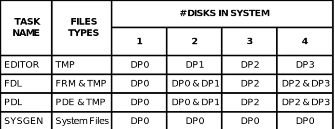
6.1.1.9 Disk Space
Several tasks need disk space in order to operate properly. The ESS editor creates large TMP files when editing a file or preparing to print. FDL and PDL need space to create forms, PDE’s and listing files. SYSGEN needs space to create new files, and to replace files that are larger. The consequence of SYSGEN running out of space on disk 0 may be catastrophic, possibly requiring a FORMAT and a resysgen to recover.
The disk on which each processor places files varies with the number of disks in the system. Table 6.1.1.9 shows which disks have critical usage by various tasks.
Table 6.1.1.9 Disks used by various tasks TASK NAME FILES TYPES # DISKS IN SYSTEM 1 2 3 4 EDITOR TMP DP0 DP1 DP2 DP3
FDL FRM & TMP DP0 DP0 & DP1 DP2 DP2 & DP3 PDL PDE & TMP DP0 DP0 & DP1 DP2 DP2 & DP3
The amount of needed space varies, depending on what the task is doing. A minimum of 2000 contiguous free sectors and a total of 3000 free sectors is recommended for each disk. An FCHECK can be done periodically to determine disk space availability.
6.1.1.10 Starting Jobs (Restrictions)
1. When HIP submitted jobs are running, the commands START and SAMPLE (with parameters) are not allowed.
2. When Tape, Disk, or SAMPLE jobs are running, the commands START and SAMPLE are allowed. In this case the SAMPLE command may be entered with or without parameters.
3. If a job includes GRAPHIC= or FILE= DJDEs to create perm-anent files on the printer, then subsequently uses those files, then this job must be allowed to complete before another job can be started. If this is not done, unpredictable results will occur.
6.1.1.11 Accounting Page Information
The accounting page information has been compressed to allow it to completely fit on a 10 inch page. This can be undone by copying ACTLDL.SYS off of the SST after the sysgen process is complete.
6.1.2 SOFTWARE
6.1.2.1 INPUT
6.1.2.1.1 Compatibility with other JDL Formats
4635/4635 MX has expanded the JDL format to include 9 parameter presence words. As such, any JDL generated using the 4635 PDL compiler will cause a crash on other 4000F printers. However, any 4000F generated JDL files will be compatible with 4635. Those 4890-unique features will be handled gracefully by 4635.
6.1.2.1.2 DJDE Processing
If the user JSL is coded with ’GRAPHICS=NO’, the DJD task will not recognize DJDE graphic commands (ALTER, BATCH, CANCEL, IMAGE, INDEX, SAVE). The following two conditions will occur:
- an INVALID command error message will be printed on the operator information sheet
- a SYNTAX error message will be displayed on the screen.
6.1.2.1.3 Color Compatibility (Standard Color Form Files)
Standard color forms are not provided with the 4635 V3A Release software. However, the 4635 supports printing of these forms.
6.1.2.1.4 Logos and Images in relation to Forms
Forms which reference images do not have the constraints imposed on them as with forms referencing logos. The user may mix color forms with non-color images.
6.1.2.1.5 Bar Code
JSLs using the BARCODE statement must be recompiled.
BSEQ is used to either reset the sequence number at the start of a report (RESET), not reset the sequence number (NORESET), or, recognize the presence of bar codes without specifying sequence numbers (NOSEQ). The 4635 makes the determination to perform RESET/NORESET/NOSEQ processing at the start of every report. The start of report for BSEQ processing includes any DJDE packets specified prior to any data in the report. Any BSEQ DJDE’s specified thereafter will be ignored, including any JDE/JDL DJDEs.
6.1.2.1.6 Segment Management
In aSegment management job which specifies RSTACK criteria and PRINT=TRAY, output destination=BIN and SEP=FIRST, the Delimiter packet at the beginning of the data stream which satisfies the RSTACK criteria will be printed on a sheet regarded as the first data sheet and will be delivered to both the TRAY and the BIN. The copy delivered to the BIN is essential since this is a separator sheet (with SNUMBER text if applicable) and must be grouped with the rest of the job.
6.1.2.1.7 Jobs Running from the ESS Disk
When running a disk job where the data file which resides on the ESS disk was created by using ESS EDITOR, the size of all DJDE packets can not be more then 72 characters including the terminating END command. Otherwise, the EDITOR’s line number will be treated as part of the DJDE packet.
6.1.2.1.8 DJDE C Command
When the DJDE record starts with a comment, then the whole record is treated as a comment. Any DJDE parameters specified after the comment but within the same comment record will be treated as a comment. This implies that the comment record need not require a comma or semi-colon to terminate the comment. An end-of-record will suffice.
When a DJDE record starts with some parameter other than a comment and is immediately followed by a comment within the same record, then the comment DJDE must end with a comma or semi-colon. This implies that a comment specified in this manner may not use comma or semi-colon as part of the comment since it will be treated as a comment delimiter.
6.1.2.1.9 X850 Host Type
X850 is no longer supported as a host type.
6.1.2.1.10 Interpress Job From Tape
Interpress job running from tape is no longer supported.
6.1.2.1.11 Online File Processing Jobs
File processing jobs, such as one that does font downloading, perform a cleanup step after the Input task knows that Output is no longer working on the report. In some cases the cleanup occurs at the start of the next job. In some cases cleanup occurs when Input is attempting to exit to do an EDIT, TAPE, FILE, etc or other non-print action. There is no message displayed indicating the activity as it is usually brief, but for some many-file file processing jobs the
6.1.2.1.12 BSELECT TEST Criteria
When specifying the test criteria for the BSELECT command, users must specify CONSTANT mode. No support is provided for CHANGE mode criteria for the BSELECT command.
6.1.2.1.13 FDL and PDL
The 4635 will support color data stream compatibility. JSLs with color statements specified can be compiled with the 4635 PDL compiler. However, due to the problem associated with the form and logo having the same file format, the 4635 FDL compiler does not support color FSLs.
6.1.2.1.14 JDE Ink Abnormal Errors
For any JDE ink abnormal errors (i.e., JDE forms call out where the form uses an undefined ink) , Input will use the parameter in the ABNORMAL ERROR statement to decide how to handle the error condition. This is a change to the way 4850 would handle the error condition where it would immediately abort the job.
6.1.2.1.15 RFEED Command
The first data record that passes the RFEED criteria for the page will be used to determine the cluster to use.
6.1.2.1.16 DJD IDEN Statement
The IDEN statement with its associated parameters (PREFIX, SKIP, OFFSET, OPRINFO) are treated as a set. If an IDEN statement is specified at both the system and job level, then all parameters that are not specified at the job level will not default to the system level parameters
6.1.2.1.17 Input Processing Hardcopy
XPPI and XDGI Release 3.1 or earlier images are formed such that a HARDCOPY cannot be performed on them. HARDCOPY requires an accurate implementation of the .IMG header block. This is a known HARDCOPY limitation. XPPI and XDGI Release 4.1 have correct .IMG header implementation.
Maximum Block Size
The maximum block size that may be processed by Input is 24,576 bytes. The Input task has increased the dynamic memory space available; thus, it is able to allocate at least one input buffer for off-line tape jobs where the tapes are written in blocks as large as the maximum length allowed.
SAMPLE Command - Aborting a job
When aborting a SAMPLE operation that is utilizing a mask option, enter ABORT job id to completely abort the job. For more information refer to the Operations Reference under ABORT.
Tape Job Operations
Data found nothing to print, or an occasional INPUT crash may occur.
To avoid this problem, key in TAP REW or TAP UNL from the console.
Invalid Font File Header Error Message
Logos are checked, just as fonts, for a valid orientation byte, the first byte in the logo header. Valid orientations are Portrait, Landscape, Inverse Portrait, and Inverse Landscape, and these appear as the ASCII letters P, L, J, and I, respectively. If Input Processing encounters a logo that does not contain a valid orientation, the system displays the name of the logo and the 'Invalid font file header' message.
6.1.2.1.18 INTERPRESS
Intepress Scaling of Images
Automatic scaling of 300 spi .IMG files for printing at 600 spi may not appear correct for Interpress jobs. The two most common cases are images referenced from a Viewpoint document in an Image Name frame and Proof Copy jobs submitted from a 150-GIS on user request.
The advanced functionality of RIP allows precise scaling of images. Thus, documents printed on a printer with RIP may be scaled differently from a printer without RIP. Use of VIEWPOINT's Image Name frame is one example. Images referenced from these frames will be scaled to the size of the frame. Therefore, modifications to the frame size will change the size of the resulting image. IMG type compressed images always have integral scaling applied. You can invoke fractional scaling with the INTERPRESS=FRACTIONAL option in ENET.JSL file.
Integral scaling is defined as integer increments from 1 to 8. For IMG/IM6 type compressed images or if RIP is not present, Integral scaling will apply; i.e., an image cannot be scaled down at the printer. Consequently, the minimum scale is 1. When an image is requested in a Viewpoint document via an image Name frame, the size of the frame is the requested size of the image. In most cases, an unmodified Image Name frame would indicate a size smaller than the actual .IMG size. The previous is also true at 600 spi, therefore, the resulting scale factor of 1 would cause the image to appear one quarter the size of the same .IMG at 300 spi. An adjustment of the size of the Image Name frame in the Viewpoint document to more closely conform to the actual .IMG size would solve this incompatibility. SAMPLE OR HARDCOPY provides the height and width of images in pixels. Dividing these numbers by the resolution of the image (also available in the SAMPLE and HARDCOPY statistics) converts the height and width units to inches which may be used to set the image frame size.
The 150-GIS submits a Proof Copy job to the printer as per the Printing Service Integration Standard (XNS Standard 198506). The 150 does not specify the optional parameter for the Control vector ’scale’. The following sentence is taken form the PSIS and defines what a printer must do in the absence of ’scale’. “If scale is absent, the scanned image is assumed to be at printer resolution and no adjustment is made.” According to this
description, the same image would appear one quarter the size (half the scale factor) when printed at 600 spi versus 300 spi.
If a 300 spi Proof Copy job is going to be imaged at 600 spi and the reduction in size isn’t satisfactory, ENET.JSL may be edited to request a resolution of 300 spi.
Accounting Sheet
Though the File Receive time is listed in the Accounting Sheet for interpress documents, it is not used, the value for File Receive time is set to zero.
ENET.JSL
Modifying ENET.JSL to use forms on Interpress Jobs is not sup-ported. For FRM inclusion in Interpress Jobs, please use a FRM definition in a frame.
Segment management is not supported in Interpress jobs. 6.1.2.1.19 IPD
The maximum paper size supported by IPD is 8.5’’ x 14’’.
6.1.2.2 OUTPUT
6.1.2.2.1 Imaging Faults
The retry algorithm for imaging faults is such that once an imaging fault is encountered, the page will be retried only once more, rather than twice as in previous releases. If the page cannot be imaged a second time, and it is determined that ”reduced performance mode ” will not correct the problem, then the printer will cycle down with a message to the operator. The operator will have the option of continuing the job or aborting it. Should ”CONTINUE O” be selected the bad page will be skipped.
6.1.2.2.2 Output Processing PFEED
In ordered stock jobs, such as with tabs, care must be exercised when selecting the PFEED tray. Jam recovery will not work properly if the tray selected for PFEED is one containing ordered stock.
OSTK Restriction
The P/L parameter permits tab stock to have both portrait and landscape options. The supported tab stock is portrait (P) which is the default condition. If landscape (L) is selected and the actual tab stock is loaded such that the tab is located on the registration edge (outboard) this combination will not run due to skew induced jams within the IOT.
FONTS, FORMS, and GRAPHICS commands with Duplex Pages
The 4635's resource handling design requires that all fonts, forms, and images for both sides of a duplex sheet be loaded into memory before the sheet can be fed. The consequence is that the values of the FONTS, FORMS, and GRAPHICS commands apply not just to a single page, but to the total requirements of both sides of a duplex page. For example, if the front side uses 30 fonts and the back side uses 40 other
6.1.2.2.3 Reduced Performance Mode
This refers to a feature which enhances the handling of dense pages. The printer will accept a lower pages per minute value in exchange for correctly printing a job.
If a page is encountered which requires longer than one page timeto ”fill” (i.e. create the raster bitmap), then the printer will purge sheets to the purge tray. The printer then determines whether the page may be ”filled” correctly if given a little bit more time to process. If not, then a ”Page Density Error” is declared and the printer cycles down.
If, however, it is felt that the page might be processed correctly given more time, then the printer enters ”reduced performance mode.” This means that paper path holes will be inserted prior to the dense page in an effort to allow the required time for the ”filling” to complete. The maximum number of paper path holes that will ever be inserted is the ”scheduling offset” - 1.
Once this mode is entered the system continues to insert paper path holes prior to every sheet until an overall average shows that ”filling” times have fallen back to normal. Then the system will terminate ”reduced performance mode” and print normally thereafter.
Messages to the operator are displayed when ”reduced performance mode” is entered and when it is terminated. No special action is needed--it happens automatically.
6.1.2.2.4 Accounting
Accounting Sheet Processing Time
When ACCT USER = BOTH is specified in the JSL, the two accounting pages will show different values for “Output Processing Time.” The sheet sent to the stacker will show a time about one second longer than the the sheet sent to the sample tray. All other values should match.
Accounting Sheets and Bypass Transport
When accounting sheets are sent to the sample tray as user sheets are going to the bin, skips are inserted by the IOT into the paper path to guarantee sequential delivery. This can be avoided by sending accounting pages to the bin.
Accounting pages for reports sent to the bypass transport are *forced* to the sample tray, regardless of where the destination is by job programming. What this means is that the only way to guarantee optimum performance for BT jobs is to specify that no accounting pages be provided.
Accounting in Segment Recovery
If segment recovery should be necessary, pages in the current segment will possibly be reprinted. The set of pages for that segment printed prior to the problem will be discarded. The 4635 will NOT count this first set of pages in the accounting file or on the accounting sheet. The 4635 page count will reflect only the number of "actual" pages in the job.
This is in contrast to the 9000F, which counts every page printed and delivered, whether or not the sheet is ultimately discarded due to a segment recovery situation.
It is possible on the 9000F for the 'Pages delivered by Output' count to exceed the 'Pages processed by Input' count for this reason. This will not happen on the 4635.
6.1.2.2.5 Segment Spec/Finishing (End of)
An end of segment will also occur when a new separator is specified. 6.1.2.2.6 Crash Code Reference Table
Below is the crash code reference table for the OUTPUT task. If an output rollover with CODE=*BPT is encountered, then refer to page 1 of the crash dump, or, if the system is run on level 4, when the register is displayed following the crash dump, refer to the R0 table below. This will give an idea as to the reason for the crash.
R0 R
eason
* Directive error other than IE.IDM PC Code = 3676
* I/O error (not NSF) during read attributes at task initialization 010101 Couldn’t find cluster to select
010202 Couldn’t get memory for FSC context initialization 010303 CLUSTR.LIB not there, and can’t be created 010404 CLUSTR.LIB exists, but can’t be read
010505 Read attributes of CLUSTR.LIB failed, but not IE.NSF 010606 Error in CLUSTR.LIB I/O
010707 Couldn’t find cluster to display
011000 Cluster count less than max, but no free entries 011010 Couldn’t find cluster to set preferred trays 011111 Couldn’t find MAIN/AUX cluster
020210 $ALTPB input parameters were incorrect
020220 RCL entry is not a header (FUT release processing) 020230 Duplex offset out of range during retry processing
020233 ”Reduced Performance” mode requires too many holes (higher than pitch count)
020240 $T75 marktime computation yielded a negative value
020250 Couldn’t find specified Variable Data buffer during lock/unlock 020260 Unknown command code in .BARFL
020270 Overlap error upon task memory deallocation (not EOL) 020310 PSL entry buffer has wrapped - no free entries
020320 No VDCT entry for current page during resource setup 020330 No FRMCT entry for current page during resource setup 020340 Delivered page’s PTB shows improper state for delivered page 030303 Couldn’t find ASPMSG.SYS during task initialization
030304 Couldn’t read message file during task initialization 050111 Invalid page log entry
R0 R
eason
060111 TCW conflict (XN/EJ)060222 IOT is cycled up during pre-cycleup processing 060333 Page spacing terminated for unknown reason 101111 Zero byte length GetBuffer request
101122 Trying to release already free buffer 111010 Can’t init page buffer, fill in progress 111020 Fatal error on Page Buffer Clear
111030 Error upon AIP GO was beyond table range 111040 Unexpected soft error upon AIP GO
111050 Page buffer status not appropriate for DUMP initiation 111060 Invalid status during FILL process
111070 Invalid status during DUMP completion processing 112010 First RCL entry was not a header
112020 Subsequent RCL entry *was* a header 112030 No RCL entry during resource setup
121111 Unanticipated error in IOT interface I/O (send) 121122 Unanticipated error in IOT interface I/O (receive) 121133 Hint received without cycling page sync
121144 IOT rejected a critical ESS message
121155 Abort-requested PTB is not within the last n entries
121211 IOT Crash Recovery message (AKA Job History) is wrong size 121222 IOT Job History message instructs recovery to delivered sheet 122011 Good sheet delivery received, couldn’t find active PTB entry to
match
122022 Couldn’t find PTB entry for hinted page 122033 Couldn’t find PTB entry during NBR setup 122044 Couldn’t find PTB entry for hinted page
122055 Couldn’t find PTB entry for EOS NBR processing 123211 Couldn’t get a buffer during task initialization (recovery) 123311 Couldn’t get buffer for User’s Accounting Summary Block 123322 Couldn’t get buffer for Xerox Accounting Summary Block 131313 Couldn’t find PTB entry for video-requested page 133111 Bad virtual address during VA to PA conversion 133122 Requested memory bank is not selected 133133 Bank select locked out
R0 R
eason
151522 Segment Tracking Buffer has wrapped - no free entries 151533 Segment Tracking Buffer is about to wrap...
151544 Trying to remove an already free STB entry 151555 Hit an unexpected hole in STB
151566 STB count nonzero but no STB entries 161611 Delivery Queue has wrapped (accounting) 161612 Delivery Queue has wrapped (8C processing) 161633 Too many entries in delivery queue while printing
* - This varies with the fault encountered 6.1.2.3 UTILITIES
6.1.2.3.1 FLOPPY
Sysgen with Floppy
The ability to create a bootable floppy or sysgen the machine from floppy will not be supported. It is determined that sysgening the machine from floppy is not desirable due to the speed and convenience of the Quarter Inch Cartridge.
DUM
DUM is now able to dump in EBCDIC, through the FORMAT E command, files that reside on the disk in EBCDIC format.
Image Dump Utility
Wild cards are not allowed when IMAGE PRINT is used
File Transfer
File Transfer activities must be complete before OSD or any TEM tasks is invoked.
6.1.2.3.2 IFU
IFU ADD Command
4635 no longer supports the IFU ADD command. IFU SAMPLE Command
IFU SAMPLE creates a command file that contains all the fonts to be sampled. If user types ABO, IFU task will be aborted. However, the command file may have been created already; therefore, to abort the command file, the user should type @ABO.
SST ADD Command
Syntax for use of the SST ADD: ADD/BF:n <file1> <file2>
Note that there is no space between ADD and /BF:n, a space between n and <file1>, and a space between <file1> and <file2>.
Sample Option
6.1.2.3.3 EDITOR SORT
Due to a dynamic memory limitation, the maximum number of filenames that can be sorted by the sort command depending on the amount of available dynamic memory.
LIST SORT
Due to a dynamic memory limitation, the SORT option of the LIST command is limited to only 2550 file names. If there are more than 2550 file names to be sorted, the warning message indicates the maximum number of file names to be 3600.
EDI Line Numbers
Unlike the other versions of LPS software, the V3A Editor displays the line numbers on the left side of the page.
Tape Error ”Ignore ” Option
If a media is offline and a command is issued, the following message will be displayed:
TAPE UNIT IS OFFLINE TYPE R TO RETRY
I TO IGNORE X TO ABORT
If ”I” is typed, the system will proceed as if there had been no error. For example, a TAP CAR REW command is being issued and the tape is offline. If 'I' is typed, the message REWINDING TAPE will be displayed because that message would have displayed had there been no error. It is possible for subsequent errors to occur if ” I” is typed in the first time. Beware.
FIX Command
The FIX command is used primarily to modify licensed and standard fonts/logos, as well as to format the font/logo matrix for correcting the IG version. When the FIX command finds a font matrix that does not match the correct IG version, it displays the message ’Fixing XXXXXX.FNT’ and tries to convert the matrix to fit the correct IG version. However, if a font file has previously been converted by the FIX command, then the message ’Fixing XXXXXX.FNT’ will continuously displayed on the screen when the FIX command is invoked again. This is caused by the incorrect information in the font header. To ensure accuracy, it is recommended that the user should verify the font header of the font file.
Uninitialized Magnetic Volume
If an attempt was made to read a 9 or 18 track tape that has never been written or initialized, the read operation will continue until the physical EOT is encountered.
6.1.2.3.4 SFS
SFS CREATE- if no status file exists one is created and the following
message is is displayed:
SF1000 JOB COMPLETED SUCCESSFULLY
SFS ? - if the status file exists, and is empty, the following message
If no status file exists the displayed message is:
Status file doesn’t exist, create using SFS CREATE command
The Xerox 4635 LPS Operations Reference manual indicates:
SFS ?, and performs a search for an existing status file. If the status file exists, nothing is done. If no status file can be found, a new status file is created, and the operator is prompted for warning and frequency flag settings.
6.1.2.3.5 SFT
SFT only supports the transferring of files from DSR tapes generated on a 4635 printing system. The software level of DSR tape being used for the SFT must be the same as the current system software level.
6.1.2.3.6 Meter Message in Billing Report
In the billing report, the (x100) in the meter messages denotes that the multiplication of 100 times the meter value has been done. The displayed value is the meter value multiplied by 100. For example, the displayed value for 6 pitch is 2800, this means that the meter value is 28.
6.1.2.3.7 IMP
IMP has been modified in the following areas:
1) Once IMP Trace has been initiated, it will continue to trace until: a. An IMP EXIT is given
or
b. A Sysgen (including Mini) is performed
2) Imp now captures two traces. The first trace includes information logged before the most recent rollover. The second trace is an ongoing trace of current system activity.
To print the trace containing information logged before the rollover, invoke DCD and type ”DUM U”. To print the ongoing (current) trace , type ”IMP PRI”. In either case, if there is not a trace present, the following message will appear:
”The Trace Buffer is empty, Type IMP RESET to start tracing” 6.1.2.3.8 Bad Block Entries
The markings that indicate whether a disk is marked bad by MBAIS * or by the BBU task # are missing from the FCHECK display/print docu-ment.
6.1.2.3.9 Patch History
The Patcher (PCH) logs all patches applied so that they will be printed out as part of an Abort Analysis Dump.
To obtain a copy of the patch history, key in DCD <ENTER>, and then DUM H <ENTER> (in log level 3 or 4). The messages: PATCH HISTORY FILE FULL, PATCH HISTORY ERROR, or PATCH HISTORY OPEN ERROR may be displayed during the execution of the Patcher. This indicates that patches can no longer be logged (or printed out as part of an Abort