Agile Business Process Modelling Framework and Enterprise
Architecture.
INTRODUCTION
Agile Modelling (AM) approach to developing software-based systems aims to improve system modelling process by combining best practices of selected modelling methods in a context of a particular project. “Simply put, Agile Modelling (AM) is a collection of values, principles, and practices for modelling software that can be applied on a software development project in an effective and light-weight manner” [1]. AM frees the modeller from the constraints and often – the bureaucracy of a particular methodology (none of which seems to suite all kinds of projects) and lets them become more effective in the art of modelling the system to be developed. Therefore, AM should be perceived as a
panacea for the common methodology drawbacks that slug many of the software development projects to the detriment to the interests of the project stakeholders. In author’s opinion, the main reason this idealistic perception is far from today’s reality is that AM harbours intrinsic paradox which applies to any kind of human endeavour and can be expressed as follows: the more freedom you have the more discipline you need to reach your goal. This discipline is needed on both individual and organisational level. Agile methods, more than any other require seasoned modelling practitioners and multidisciplinary methodology mentors of the highest order to configure and implement the best modelling process for the project. At the organisational level, a right-weighted strategy should be put in place to adopt an agile approach. At the minimum, the strategy should define where the organisation is now and where it wants to be at some point in the future. For example, a big-size organisation may decide to achieve Level 3 of CMM first based on a well-defined methodology and only then to augment its development process using agile modelling extensions, possibly at the Enterprise level.
A good metaphor depicting the challenges of agile approach would be coming up with a interdisciplinary program combination of yoga, gym, aerobic and let’s say aqua exercises and applying it to improve overall fitness and well-being of the program participants. Try to imagine what would be the outcome of such an ‘agile’ project without
multidisciplinary fitness experts and disciplined well-planned approach. Freedom without an in-built discipline often reverts to chaos.
As “many agile methods are perceived as architecturally weak, disconnected from the realities of delivering large systems in complex enterprise environments.” [2], the goal of this paper is to confront the dilemma of bringing ‘just enough’ discipline to the agile modelling to address the problem. As the models are the actual language of the
Architecture Framework, which in turn provides a logical structure for classifying and organizing the descriptive representations of an enterprise, the author is convinced that the best way to address the problem is by “bringing agility to architecture and
architecture to agility” [2]. Along this line, the paper provides an example of agile approach to building Enterprise Architecture by defining an agile Business Modelling Framework and applying it by using a tool independent Modelling Process. Agility with discipline at all levels!
AGILE ENTERPRISE ARCHITECTURE FRAMEWORK
An Enterprise Architecture Framework (EAF) is a generic classification scheme for all the artifacts that can be used to describe the Enterprise. In its classic form EAF is presented as a two-dimensional matrix with rows and columns defining two aspects of the Architecture (e.g. Views and Levels as shown in Fig. 1). An intersection of a
particular row and column (a cell) defines an Architectural focus. For a short overview of the most applied Enterprise Architectural Frameworks see [3].
EAF serves the following purpose:
1. Divides the enormous amount of information content into manageable chunks. 2. Provides a navigation map for frameworks and methodologies defined at the next
level.
3. Provides a sense of the contextual perspective when focusing on selected aspects of the Enterprise.
4. Helps to prevent the isolation of a single problem area from the other areas by providing a relation map between the cells.
From the business perspective, the Framework is a tool that helps to understand all aspects of the business (processes, information, people, etc.) and their interrelations. It also helps to align IT strategies with business strategies.
Figure 1. Zachman’s Enterprise Architecture Framework.
The primary strength of the Enterprise Architecture Framework exemplified by Zachman Framework [12] as shown in Fig. 1 is that it provides a single, high level map of all the possible views at the Enterprise level. However, as emphasized by many practitioners,
EAF is only a tool for thinking about the information you need to capture in the enterprise, and a vehicle for organizing, displaying, and accessing that information. In other words, EAF is only a structured container adopted by the organization and used for a strategic purpose defined by its stakeholders. In particular, EAF does not specify how many levels of modelling decomposition would be needed to reach the level of detail adequate for the purpose (e.g. improving business processes) nor does it define the
modelling process and guidelines to be followed. If applied in a rigid manner EAF can lead to a documentation heavy implementation with a lot of unsynchronised and overhead activities not necessarily addressing Enterprise needs and therefore providing limited value to the Organisation.
As outlined above, an agile implementation of EAF addressing both its decomposition and process deficiency requires creating at least two more frameworks at a grater level of detail:
• Modelling Framework
Modelling Framework (MF) is a decomposition of selected cell(s) of EAF into next level of detail. The difference of magnitude between these two levels is that while EAF cells reflect Enterprise Architecture, their extension on the MF level provides structure at the Artifact level (models, documents and other deliverables) i.e. MF defines artifact type and level which can be directly linked to a diagram or file type of a supporting toolset. As in the case of EAF, MF is defined by several different Views that can be described by system model Artifacts at several Levels. MF can be considered as a static structure defined at the artifact level that provides a roadmap for Process Framework (PF).
• Process Framework
A dynamic aspect of the framework is described by a Process that produces its static outcome contained in MF. PF is two-dimensional as well. The first dimension represents the lifecycle of the process and is expressed in terms of Phases. The second dimension is formed by Disciplines which are groups of Activities performed across several Phases (e.g. Project Management). This type of process specification described in context of inter-related Architecture Framework is often referred to as a system development
methodology (business and IT systems are typical examples of systems being developed). As each comprehensive system development process can be customised to suit the goals of a particular project we refer to it as a Process Framework (PF). A classic example of PF is RUP [5]. Examples of MF and PF will be provided and discussed later in the paper. The two-dimensional aspect of modern System Development Methodologies (Phases and Disciplines) put in context of multilayered Architectural Frameworks (such as MF and EAF) is what makes them quite difficult to understand and properly apply on a specific project with additional project constrains adding even more complexity to the equation. To address this complexity in a systematic manner a metamodel of Enterprise Modelling and Process Frameworks with their components and relationships between them has been defined in [8].
The goal of this paper is to use the concepts of MF and PF described above to provide an example of decomposing EAF in an agile manner down to the level of modelling
activities that can be used directly by the modellers using a supporting modelling toolset. The author believes that without such decomposition in place the transition from
Enterprise Architecture level down to the modelling and process levels would always remain something similar to alchemy.
BUSINESS MODELLING FRAMEWORK AND ITS RELATION TO THE ENTERPRISE ARCHITECTURE FRAMEWORK
Even though EAF may seem unwieldy for a purpose of agile modelling it in fact contains in-build flexibility for defining Modelling Frameworks at the next level. As described by Popkin Software [4]:
“The Information (models) in a specific cell of the Framework may be related to one another in a hierarchy while remaining completely within the cell. For instance, in the Enterprise Model Perspective and How Cell are what are commonly referred to as business process models. Business process models, however, come in a variety of flavours (e.g., Function Models, Process Flows, Functional Hierarchy, etc.). These models may be related to one another in a way where one adds value and information to the other, while still fitting the criteria that has them living as a part of the same cell. In theory, each cell may contain an Enterprise Architecture Framework. This nesting of Frameworks within cells may be infinite.”
Modelling Frameworks tend to fall into one of four categories: Business Process Models, Data Models, Object-Oriented Models, and Structured Models. The rest of this section provides an example of Business Modelling Framework which serves as a road map for the modelling process described in the last section of the paper. Modelling Frameworks for other three categories can be constructed in a similar way (which is beyond the scope of the paper).
Overview
Architectural models define the business structure and are the key to understanding the business and its functionality. As stated in [7]: “A good architecture allows the modeller to abstract the business into different aspects or views and to concentrate on only one aspect at a time.”
The Business Modelling Framework presented in the paper summarizes a collection of perspectives selected to describe Enterprise Business Architecture, as depicted in Figure 2. The rows represent three different levels of views from the highest organizational level to the most detailed individual job level. The columns represent different aspects or views of the Architecture.
The Three Levels of Business Modelling
In system modelling, a technique used to master the complexity of very large systems is called layering. The idea behind this technique is to separate the activity-specific parts from the more general parts of the system, so that the business units and services can be reused. When structuring organizations, the same principles are naturally applied. For example, in the bottom layer you find resources that provide job-specific services; somewhere in the middle layer you often find resources that support business-specific activities; and in the top layer you find business area-specific or product-specific
specialists, Research and Development, and sales force activities. Core business processes can use resources from all layers.
Organization level
This is the highest of the three levels that represents interactions between organizational units and external agents and shows fundamental functions and variables. Analysis of the business at this level often identifies greatest potential for performance improvement within the Enterprise.
Process Level
Process level provides workflow models or process maps which define how work currently gets done and how it should be done to support the business goals.
Business Process is a series of steps designed to produce a product or service. Most business processes are cross-functional. Examples of processes include: product/service development and introduction, order fulfilment, warranty administration. Business processes have the following characteristics:
• They have defined inputs, add value and produce defined outcomes and
deliverables.
• They have customers (internal or external) who are recipients of an outcome or
deliverable.
• They normally cross existing organization or functional boundaries. • They are measurable.
• They have defined triggers (initiating events).
Job level:
Describes in detail the activities each job is responsible for and the goals to be achieved Provides a “micro” picture of people and their immediate environment.
The Four Views of Business Modelling Architecture
To describe an organization’s operations, (current and planned) we need to examine four aspects or views of the organization (the content of each View is listed under its name):
Strategy
Business strategy
Goals
Problems
Work Flow
Organization Structure
Process and Activities Work Flow
Business Rules
Information
Business Objects: Information and Materials
Business Objects Model and Flows
Conceptual and Logical Data Model and Flows
Management
Organization management: strategy, goals, organization level flows
Process management: process administration and execution
Job management: resource and task management to optimize efficiency and effectiveness.
Information management
Having described Views and Levels of the Framework we can define the Business Modelling Framework itself.
Business Modelling Framework
The business architecture is what we use to communicate with different stakeholders about the business to ensure a common, consistent understanding. We can describe the business architecture as the framework within which we make changes to the
organization to enable the business to ultimately realize the business idea. Because business architecture is complex and difficult to measure, we divide it into a number of different views and levels, as shown in the Fig 2.
The three levels of business modelling described earlier constitute one dimension of our framework. The second dimension comprises four views specified above. Combination of the free levels of business modelling with the four views results in the Business
Modelling Framework (BMF) consisting of cells shown in Fig. 2. The content of each cell is the generic component that captures what is important when building instances of business models for the enterprise in the same way as Zachman’s framework provides a conceptual map for Enterprise Architecture.
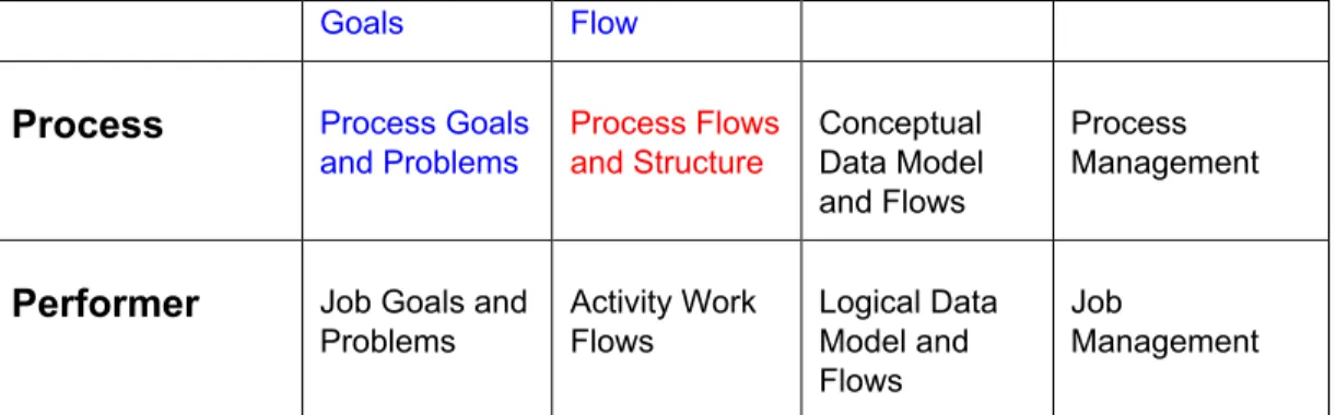
Domain Level
Strategy Work Flow Information Management
Organizational Organization Strategy and Goals Organization Structure and Flow Business Objects Model Organization Management
Goals Flow
Process Process Goals and Problems Process Flows and Structure Conceptual Data Model and Flows Process Management
Performer Job Goals and Problems Activity Work Flows Logical Data Model and Flows Job Management
Figure 2: Business Modelling Framework
Understanding the content of the BM Framework cells (and therefore understanding system development methodologies and supporting tools), is a basis for disciplined business modelling process. Without such a framework there would be little cohesion in the resultant business system implementations, regardless of how valid or robust the methodologies and tools, plus the systems would have provided little lasting value as the Enterprises changes over time.
Relation of Business Modelling Framework to Enterprise Architecture Framework As Business MF is an extension of EAF into next level of detail the cells of BMF should map to a subset of EAF. What provides for an agile way of using EAF is that the type and number of Views and Levels of decomposition chosen for MF can vary depending on the Architectural or Project goals. Some of the cells (these that are in focus) of EAF can extend (map) to several cells of MF while others (out of focus) can be left implicit. In both cases the decision which cells to put in/out of focus should be derived from well-defined goals for defining the frameworks in the first place. Defining the content, configuration and focus of MF is one of the main tasks of agile architect.
Let’s note that the cells of BMF as defined in Fig. 2 can be mapped into relevant cells in the first two rows of EAF from Fig.1; this kind of mapping is in line with the guidelines for using EAF [4]: “You may use a subset of the perspectives as long as the set chosen is immediately adjacent;”.
PROCESS FRAMEWORK AND ITS RELATION TO THE MODELLING FRAMEWORK
To navigate through the MF in a disciplined way as modelling process unfolds we need to describe the lifecycle of the modelling process itself. For that purpose the modelling process is decomposed over time into several Phases (e.g. Define, Develop and Deploy). Each Phase shows the dynamic aspect of the activities performed in the modelling process. Activities of similar nature are logically grouped into Disciplines (Business Modelling is one of disciplines in a full SDLC). Workflows of activities detail how to perform a particular Discipline at a particular Phase(s) to produce a desired set of MF Artifacts. Artifact can be produced in the form of Model Diagram (graphical model of any kind) or File (e.g. text file, source code, executable file). Workflows detailing the modelling process are usually layered themselves to gradually unfold the increasing level of details as the process is being fleshed out.
A detailed description of PF even when restricted to Business Modelling is beyond the scope of this paper. Examples of PFs include RUP, Popkin Process [10] and other methodologies focused exclusively on Business Modelling [6, 9].
Even though MF maps may cover a lot of territory, this does not mean that a particular process instantiation of PF needs to travel through all the cells of the related MF. Once again, selection of the MF cells most related to the project goals and configuring the modelling process accordingly (to be focused on those cells) is what constitutes the essence of Agile Modelling approach to the project.
As an example, let’s assume that the main goal of the project is to analyse existing core business processes of the organisation and recommend improvements and
implementation strategy for them. We will show how to define a business improvement process within PF aligned with this goal that uses Business MF from Fig. 2 as a
navigation map in an agile and efficient manner. First, as BP Management is out of scope of the project (we need to improve the processes first) the last column (View) of our MF is out of focus. Second, to deliver improvement recommendations and implementation strategy at a process level as a main result of the project the Performer level of detail is not necessary to be covered by the business analysis effort (typically – not even possible to include into the project schedule within given time and budget constrains). Thus – the third level of Business MF is out of focus as well.
The primary focus of the improvement process will be ‘Process Flows and Structure’ cell (marked in red in Fig. 2) of the MF containing diagrams of the selected processes’ flows and their decomposition structure. These should trace back to Organisation Structure and Flow which shows the structure of the organisation units used in the process flows and general flow of work showing how organization units interact with each other as well as the external environment (system view of the organisation). The project scoping diagram representing the main sub-processes to be redesigned together with the major work flows between them should be produced at this level as well. Typically six to eight
sub-processes are included in the scoping diagram. To provide direction to the improvement effort processes’ Problems and Goals linked to the Organisation Strategy and Goals should be included in the analysis as well. These three cells of the MF will therefore constitute a secondary focus of the improvement process (marked in blue). The process flows diagrams might also show Business Objects used as inputs and outputs of the process steps. Thus, an initial Business Object Model can be drafted at this stage as well (third priority cell marked in green).
The kind of topology of the improvement process as described above – one main cell in focus spreading out into adjacent cells is characteristic of modelling processes. Process-centred approach is the most typical of modern system architectures [7, 9]. The other common approach is to focus on Data Models and Flows cell (data-centred approach). Deciding which cell use as a main focus (Process or Data) is one of the main architectural decisions at this level.
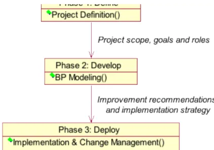
To describe the dynamic of our Business Improvement Process let’s define its three Phases: Define, Develop and Deploy as shown in Fig. 3 (as is the case e.g. in the well-known Rummler-Brache methodology [11]). The Deploy Phase is shown as context only the assumption being that the project formally ends with delivery of the improvement recommendations and implementation strategy (Go/No Go decision is then made for an implementation project).
The main activity of Define phase is Project Definition as a result of which project scope, goals and roles are defined. During this phase the Case for Action is prepared,
sponsorship for the project is developed, the project is initially scoped (how much to attack in this project), and the internal climate is assessed. This phase will operate at the Organisation level and deliver artifacts that belong to the upper two cells.
Main artifacts of the project will be produced as a result of BP Modelling activity of Development phase and we will describe it in more detail (Define phase can be described in the same manner).
Figure 3: Three Phases of the BPM Project.
BP Modelling defined for our project consists of two activities: IS Analysis and SHOULD Design. The objective of the IS Analysis is to describe how the process is being performed now and how well it is performing in order to improve the process for the future. In the SHOULD Phase the new process design to meet the Project Goals is prototyped, and the high-level requirements for the infrastructure are developed.
IS Analysis
SHOULD Design
Figure 4: BP Modelling Activities.
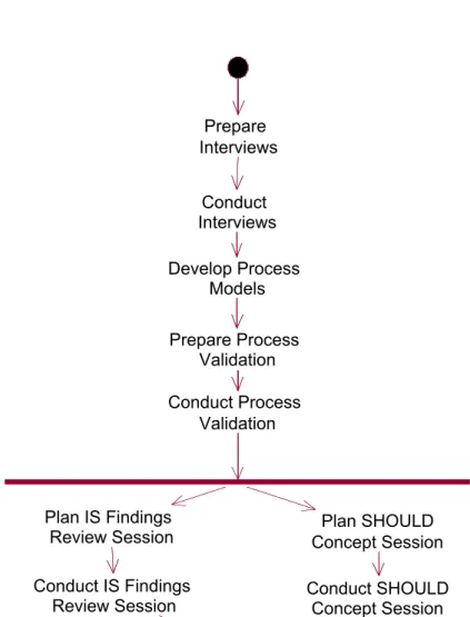
IS Analysis consists of a number of Steps that can be modelled as an UML Activity Flow diagram in Fig. 5. Responsibility for each Step can be assigned to a designated and defined role(s) such as Process Owner, Design Team, Steering Team, Stakeholder etc. This can be defined on a project basis and shown using swim-lanes. Defining the Work Flow Diagrams of this type showing how the modelling process will actually work on the project can be done using the principles of Agile Modelling [1] and should be assigned to a senior staff member such as Project Mentor or Process Engineer.
Needless to say, SHOULD design can be described in a similar way (through its Activity Flow diagram). Prepare Interviews Conduct Interviews Develop Process Models Prepare Process Validation Conduct Process Validation Plan IS Findings Review Session Conduct IS Findings Review Session Plan SHOULD Concept Session Conduct SHOULD Concept Session Figure 5: IS Analysis Steps.
Each Step is then decomposed into consisting Tasks that show Input and Outcome (deliveries) of the Project at the lowest level (an example of Prepare Interview Tasks is shown in Table 1.
Table 1.
Task Input Tool Outcome
Task 1:
Finalize Interview Schedule
List of interviewers and interviewees along with their locations and available interview sites IS Interview Scheduling Guidelines Interview schedule distributed to all interviewers Task 2: Prepare Interviewees
Interview schedule Pre-Interview Communication Interviewees prepared Task 3: Acquire Background Information Interview schedule and Project Definition Worksheet
None applicable Interviewer prepared
Each Task is yet further detailed by specific Guidelines (such as Modelling Guidelines, Patterns or examples such as the one shown in Fig. 6) and Document Templates (e.g. Business Rule document template).
XYZ Corporation Sales Finance Human Resources Manufacturing Marketing Product Management Product Marketing Lead Management Product Development Labor Markets Research Community Capital Markets Market Partners Customers Suppliers People Technology Capital Market Feedback Market Feedback Sales Forecasts Sales Orders Product Specifications Software Purchase Orders Supplies Leads Customized Solutions Software Customized Solutions Sales Tools Leads Technical Assistance
Figure 6: Organisational Flow of XYZ Corporation.
The Project Guidelines and Templates at the Task level should be geared to the development environment with its supporting tools, team preferences and experience, and/or Project constraints (e.g. using a particular modelling notation such as BPMN as a standard). Project Guidelines and Templates are the main body of the knowledge base of
the project and are extensively used and referred to by all project participants responsible for the quality of its deliveries (business analysts, reviewers, project mentor(s) and managers alike). Such Guidelines and Templates can be adopted from a generic
knowledge base (such as RUP, Rummler-Brache etc.) and customised at the organisation level to form Enterprise body of knowledge supporting its Architecture Framework. CONCLUSION
EAF provides a conceptual think-map for developing architecture at the enterprise level. Agile Modelling technics provide flexible solution to system modelling needs at the project level. The ‘white space’ between EA and AM poses significant issues on both sides. Without a systematic approach to address this gap EA will be perceived as an ‘ivory tower’ type of construct by hard-core modellers working on specific project tasks while the deliveries of the later will be often construed as ad-hoc improvisation of questionable quality aimed to address nagging project needs rather than provide value from the organisation point of view.
The paper provides conceptual road map for building Architectural Frameworks and decomposing them in a disciplined, traceable manner into system modelling level so that the gap between the two can be bridged with a comprehensive logical approach from both sides.
References
1. Agile Modelling, http://www.agilemodelling.com 2. Agile Architect, http://www.agilearchitect.org
3. Architecture and Architecture Modelling Techniques, S.W. Ambler,
http://www.agiledata.org/essays/enterpriseArchitectureTechniques.html#MDA 4. Building an Enterprise Architecture: The Popkin Process, downloaded from
http://www.popkin.com
5. Enterprise Unified Process, http://www.enterpriseunifiedprocess.com
6. H.E. Eriksson, M. Penker, Business Modelling with UML, Rational Software White Paper, downloaded from http://www.rational.net/
7. H.E. Eriksson, M. Penker, Business Modelling with UML, Business Patterns at Work, J. Wiley & Sons, 2000.
8. Z. Jackowski, Metamodel of the System Development Method, Agile Alliance, http://www.agilealliance.org/articles/articles/MetamodelOfSDM.pdf
9. Z. Jackowski, Business Modelling with UML: A Process Centered Architecture, Agile Alliance, http://www.agilealliance.org/articles/articles/BPM.pdf
10. Popkin Process, Popkin Software White Paper, downloaded from http://www.popkin.com/
11. G.A. Rummler, A.P. Brache, Improving Performance, How to Manage White Space on the Organization Chart, J. Wiley & Sons, 1995 (second edition). Link:
http://www.rummlerbrache.com/