6032
MICRO CONTROLLED AND DIRECTED ALARM SYSTEM
FOR BLIND PERSON
Dr. RASHID A. FAYADH
Middle Technical University, College of Electrical Engineering Techniques, Baghdad, Iraq E-mail: [email protected]
ABSTRACT
Blindness is a lacking state of visual perception due to neurological or physiological factors. Partial blindness represents the integration lack in the optic nerve growth or the eye visual center. The total blindness is defined as the full absence of light visual perception. The deaf and blind persons are frequently suffering at mostly exercising of basic things in daily life. This suffering makes lives almost at risk during traveling through obstacles, due to necessary equipment lack in my country that provides them an assistance state to avoid or cross over the risk. For this reason, the idea of research was come to design and manufacturing ultrasonic sensor. The proposed work contains friendly user, cheap, and simple alarm system that is implemented and designed support the mobility of both visually impaired and blind people in a specific area. This work includes wearable equipment that consists of cummerbund for helping the blind person in the way navigation safely alone by avoiding encountered obstacles whether mobile or fixed to prevent any possible hard accident. The main system component is the ultrasonic wireless sensor which is used for scanning the predetermined around area of the blind by emitting-reflecting waves. The echo or reflected signals are received by Arduino microcontroller which are coming from barrier objects. The issued commands are carried out by the microcontroller to communicate the status of device back or given appliance to the vibration device. In this project a sensor is used to detect around obstacles within 150 cm of designed range. It can change the distance by simply changing the variable resistance button to avoid the blind person through the vibration when there is a risk.
Keywords:Arduino Microcontroller, Blind Mobility, Blindness And Darkness, Emitting Reflecting Waves, Ultrasonic Sensor.
1. INTRODUCTION
Sound is defined as mechanical vibration uses elastic medium to transmit. The frequency range of humans hearing is approximately 20 Hz to 20 KHz. The previous range is audible frequency spectrum that varies individually and reduces with age. Any ear senses frequencies around 3.5 KHz. The sound below 20 Hz known as infrasound and over 20 KHz is known as ultrasound [1].
Ultrasound is oscillating sound with frequencies greater than the range of human ability hearing. It is not separated fare of normal or audible human sound by differences in physical properties of sound and in fact the ears of human cannot hear sound over this range. Although this range limit varies between persons which is approximately 20 KHz in healthy spatially in young adults. The ultrasound device operates with frequency range starting from 20 KHz up to many gigahertz and use in many different science fields. So that, ultrasound devices are used for detection of measure distances
6033 heard by adults or younger humans. Older people can hear signals around upper hearing threshold because of age considerable variation of related deterioration. Electronic devices (Mosquito) are used for high pitched frequency by young people to deter loitering [4].
Additionally, this paper was organized to represent the ultrasound navigation in Section 2. Section 3 shows ultrasonic sensor. In Section 4, the microcontroller Arduino is presented to implement architecture of AVR. Arduino programing analysis is given in Section 5. Finally, Section 6 represents system design and practical implementation and section 7 appropriates conclusions.
2. ULTRASOUND NAVIGATION
[image:2.612.312.535.80.229.2]In the darkness, bats use ultrasounds for navigation and to detect frequency bands beyond 100 KHz up to 200 KHz for echo hearing of reflected emitting sound to know its location from obstacles during the fly in darkness as shown in Figure 1 [5]. To identify ultrasound, there is an Indoor Positioning System (IPS) or Real Time Locating System (RTLS) technology used automatically for tracking and identifying in real time the location of objects. These can be done by using simple, embedded in objects and devices or inexpensive nodes (badges/tags) attached to devices. Then transmit an ultrasound signals for communication of their location to microphone sensors. The sound travel speed depends on the nature medium that passes through. In general, the sound speed is proportional to its density and to the stiffness of the medium (the square root of the ratio) which it is a fundamental of medium property. The speed of sound and physical properties are changing with depend on conditions of environment. The speed of sound is approximately 343 m/s in the air and depends on the surround temperature, in a bar of steel 5000 m/s, and in water the speed is 1500 m/s. There is a common use of ultrasound is to find range and also called sonar which is working similarly to the radar. The ultrasonic pulses are generated in a particular direction. These pulses are reflected back as an echo to the sender and the detection will take place. Measuring of time difference between the received echo and transmitted pulses gives determination to how the object is far away. This variety of ultrasonic frequency ranging is used by bats to detect their location or prey (echolocation).
Figure 1. Ultrasounds are used by bats for navigation in the darkness [5]
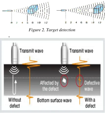
For proposed system, it is important to measure the distance of reflected sound signal which is a longitudinal wave to strikes a flat area surface that usually the shape of indoor obstacles. This hard and smooth surface is to reflect a greater amount of incident signal than a soft surface, while rough surface reduces the dissipating or operating distance of ultrasonic sensor and leads to decrease the sensor accuracy. Sound is then reflected, provided that the dimension of the reflective surface is large compared to the wavelength of the sound and shorter distance from ultrasonic sensor provides stronger echo. The required part of this research is to detect the reflected signals from near and far surfaces with angle of far surface signal to change the direction of the blind through indoor walking.
3.
ULTRASONIC SENSOR
6034
Figure 2. Target detection
,
Figure 3. Defective wave through materials
Figure 4: Time-Frequency Representation of the UWB Wavelet Transform
4. MICROCONTROLLER AND ARDUINO
To make a complete microcomputer system, only micro- processor is not sufficient. It is necessary for this system to add other peripherals such as read/write memory (RAM), read only memory (ROM), drivers, decoder, and number of I/O devices to make a complete microcomputer system. In addition, special purpose devices, such as interrupt controllers, programmable timers, programmable I/O devices, DAM controllers may be added to improve the capability and performance and flexibility of a microcomputer system. The Microcontroller corporate all the features in microprocessor, it has also added features to complete microcomputer system on its own. The microcontroller has built-in RAM, ROM, Serial I/O, Parallel I/O, clock circuit, and counters. Advantages of built-in peripherals are listed below [6]:
1. They have short access times which lead to more speed.
2. Their hardware reduces due to small single chip microcomputer system.
3. Less hardware increases reliability of the system and reduces the PCB size.
Microcontroller unit (MCU) is a single chip computer to make small device for controlling many applications. Another term for microcontroller is embedded built controller in devices they control [7]. A microcontroller or MCU is a computer implemented on a single very large scale integrated (VLSI) circuit. To mention the microcontroller families, there are five major microcontrollers of 8-bits. They are: Free scale Semiconductor's (formerly Motorola) 68HC08/68HCII, Atmel's AVR, Intel's 8051, Zilog's Z8, and PIC from Microchip Technology [8]. Since in this project the microcontroller used is one of the Atmel's family so we will focus on the AVR Microcontroller, Zilog's Z8 Microcontroller, and PIC Microcontroller. AVR microcontrollers are available in three categories:
1. Tiny AVR is suitable only for simpler applications because of small size and less memory. 2. Mega AVR is the most popular ones having higher number of inbuilt peripherals, with a good amount of memory (up to 256 KB), and suitable for complex or moderate applications.
3. Xmega AVR is commercially used for complicated applications, which requires large program memory and high speed.
4. Mega AVRs (ATmegaxxxx) are powerful microcontrollers with instructions more than 120 and lots of different peripheral capabilities that used in different designs. In addition, some of their characteristics are package of 28 to 100 pins, program memory of 4K to 256K bytes, extensive peripheral set, and extended rich instruction sets.
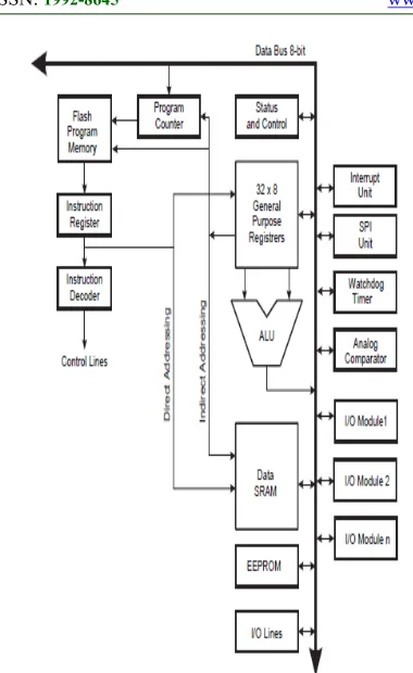
4.1. Microcontroller Architecture
6035
Figure 4. Block Diagram of Microcontroller Architecture (AVR)
4.1.1. Memories
In microcomputer system, memory is an important part and classified into data memory and program memory depending on their applications. Program memory is read-only memory (ROM) that stores all the program codes. Other types of memories such as EPROM and PEROM flash memories are generated and used for low-volume applications. Data memory is a read/write memory (RAM) for complex applications of large amounts of memories and can be used to interface external memory chips to most microcontrollers. The following memories are considered in microcontrollers:
• Flash – It is card's flash memory used to store program code or to microcomputer board and this memory is nonvolatile that's mean the contents of flash memory remain intact when the board is disconnected from its power source. Memory of 2K to 8K can be used for the stored software that allows us to communicate with external devices. • SRAM – It is Static Random Access Memory (SRAM) where program data is getting stored during processor execution of program and can be lost at removing power from the controller board. • EEPROM – It is nonvolatile Electrically Erasable Programmable Read Only Memory (EEPROM)
where data is stored and need to be retrievable after removing the power from board or restored.
4.1.2. Arithmetic logic unit (ALU) and status register
The ALU operations are divided into three main categories bit-functions, logical, and arithmetic operations between registers to execute data. Some architecture implementations provide a powerful multiplier to support both signed and unsigned fractional format and multiplication. The result of the most recently executed arithmetic instructions are contained as information in status register. This information is used to alter the program flow for performing conditional operations.
4.1.3. General purpose register and stack pointer
The purpose register file is optimized for the AVR enhanced RIS instruction set. To achieve the required enhanced performance and flexibility, most of the instructions are operating on the Register File have direct access to all registers, and most of them are single cycle instructions. The stack is mainly used for storing temporary data, local variables, and return addresses after subroutine calls and interrupts. The stack pointer register is implemented as growing from higher to lower memory locations and always points to the top of the SRAM stack area.
4.1.4. Microcontroller I/O pins and execution timing instruction
The AVR microcontroller has from 3 to 86 pins for I/0 ports and this number depends on pins number in the package itself. In this proposed work, the number of used pins for the AVR package is from 8 to 100 pins. There are 3 pins for I/0 in case of the 8-pin AT90S2323 while 86 8-pins can be used for I/0 in case of the 100pin ATmegal280. The execution timing describes the general access timing concepts for instruction execution such as AVRCPU is driven by the clock of CPU which is directly generated from the specialized chip for selected clock source.
4.1.5. Microcontroller peripherals
6036 channels that is depending on package pins number. There are 6 timers besides the watch in the AVR. The presenting of USART peripheral allows us to make connection between AVR-based system and serial ports such as the COM port of the x86IBM PC. Most of the AVR family members come with the SPI and I'C buses and some of them have CAN bus or USB as well.
4.2. Microcontroller Programming (I/O Ports)
Port pins are configured either as output or input to be bidirectional ports. There is corresponding TRIS register for each port to determine if the port is designated as output or input. A value of 0 in the TRIS register port is making the mapped port as output and a value of 1 is making port as input. Typically, input ports are used to communicate with input devices such as input data lines from external hardware devices or keypads and switches. Output ports are used to communicate with output seven-segment displays. Although port pins are bitmapped to be read and write units. For example, the PORTA register holds status of eight pins that possibly mapped to Port-A, while writes to the port latches and these operations are actually read, modify, and write operations. In other words, the port pins are first read and the value is modified, and then written to the port’s data latch. Some of the port pins are multiplexed; for example, pin RA4 is multiplexed with timer 0 module clock input; therefore, it is labeled RA4/T0CKI pin. Other PORTA pins are multiplexed with analog inputs and with other functions. Data sheets for device contain information about the processing functions assigned to each pin. All AVR ports have true Read-Modify-Write functions when they are used as general digital I/O ports. This means that the direction of one port pin can be changed without unintentionally changing the direction of any other pin with the CBI and SBI instructions. The same function applies at changing drive value of configured input and output. Each output buffer has got symmetrical drive characteristics with both source cap ability and high sink to directly drive LED displays. There are individually selectable pull-up resistors for all port pins with supply voltage invariant resistance and all I/O pins have got protection diodes to both Ground and VCC. Each port pin consists of three register bits such as PINxn, PORTxn, and DDxn. The DDxn bit selects the direction of this pin in the DDRx Register, if it is written logic 1 or logic 0, Pxn is configured as an output pin or input pin, respectively. To switch off the pull-up resistor, PORT xn has to be written
logic 0 or the pin has to be configured as an output pin. Port pins are tri-stated selection, no clocks are running when reset condition becomes active. General Digital I/O Ports
These ports are I/O bi-directional ports with optional internal pull-ups. Functional description of one I/O-port pin, here generally called Pxn (General Digital I/O).
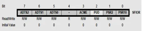
Alternate Port Functions
Most of port pins have alternate functions in addition to being General Digital I/Os. Figure 5 serves as a generic description applicable to all port pins in the AVR microcontroller family.
[image:5.612.315.541.317.367.2] Special Function I/O Register – SFIOR Bit 2 is Pull-up disable (PUD) bit and this bit is written to one disabled /O ports of the pull-ups even if the PORTxn and DDxn registers are configured to enable the pull-ups ({PORTxn, DDxn} = 0b01).
Figure 5. Port pins in the AVR microcontroller family
4.3. Timer and Counter
Timer/Counter 0 is a general purpose with PWM of 8-bit module and single compared unit. The main features for this Timer/Counter are Glitch-free, Phase Correct PWM, Single Compare Unit Counter, Frequency Generator, Clear Timer on Compare Match (Auto Reload), 10-bit Clock Prescaler, External Event Counter, and Compare Match Interrupt Sources (TOV0 and OCF0). The Timer/Counter is internally clocked to via the prescaler, or on the T0 pin by an external clock source. All times, the Timer/Counter value is compared with the double buffered Output Compare Register (OCR0). The comparing result is used to generate PWM by the waveform generator or output variable frequency on the Output Compare Pin (OC0).
4.4. Interrupt
6037 Program Counter that is known as actual interrupt vector to make execution for interrupt handling routine and clearing the corresponding interrupt flag. Also interrupt flags are cleared by writing a logic 1 to the flag bit positions. When interrupt occurs at cleared corresponding bit of interrupt enable, the interrupt flag will be remembered and set until the flag is cleared by software or the interrupt is enabled. Similarly, if one or more interrupt conditions occur at cleared Global Interrupt Enable bit, the interrupt flags can be remembered and set until setting the bit of Global Interrupt Enable, and it is executed by priority order. The second type of interrupts are triggering as long as the interrupt condition is present so not necessarily having interrupt flags. This interrupt will not be triggered when the interrupt condition disappears before it is enabled. Because of an interrupt, AVR exits and always return to the main program and execute one more instruction before any serving of pending interrupt. Status Register is not automatically stored when entering an interrupt routine, nor restored when returning from an interrupt routine which is handled by software. To disable interrupts, CLI instruction is using and no executing the interrupt after the CLI instruction even it simultaneously occurs. The bellow programmed example was done to show how this can be used to avoid interrupts during the timed EEPROM write sequence.
Char cSREG;
cSREG = SREG; /* store SREG value */ /* disable interrupts during timed sequence */ _CLI();
EECR |= (1<<EEMPE); /* start EEPROM write */ EECR |= (1<<EEPE);
SREG = cSREG; /* restore SREG value (I-bit) * 4.5. Arduino
Arduino is an open source physical computing platform based on input/output (I/O) board and a development environment that implements the Processing language [9]. It is used to make development for standalone interactive objector that is connected to software on personal computer. The Board is assembled by purchased preassembled or hand. It is a multiplatform environment and run on Linux, Macintosh, and Windows. It is based on programming process of IDE and easy to use development environment by designers or artists. The programing is done by USB cable, so not a serial port and expressed as useful because of most
modern computers are not supplied with serial ports. It is open source software and cheap hardware with circuit diagram can be downloaded and buying all the components to make own Arduino without paying anything to designers. The cost for USB board is about US$35 and easy to replace a burnt-out chip on the board that costs about US$4, so be afford to make probability mistakes. For these reasons, Arduino Projects were developed in scientific laboratories or educational environment and be great for newcomers for getting things work quickly. The Arduino philosophy is based on making designs and it is constant research for faster processing with more power full ways to build up better prototypes. So that, several prototyping techniques have been explored and developed ways of thinking by own hands.
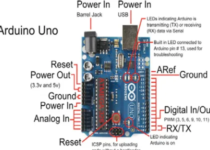
4.6. Arduino Architecture
Arduino Uno hardware is shown in figure 6 and the physical parts are introduced bellow in more detail:
4.6.1. The USB and power connectors
On the board and at the far left there is a Universal Serial Bus (USB) port connector. By this connector, the board is connected to the personal computer for three main reasons, firstly, to upload your instructions to the Arduino, secondly, to supply power to the board, and thirdly, to send and receive data from operating computer. At the right of the board, there is a power connector to power the Arduino with a standard mains power adapter.
4.6.2. The microcontroller
The microcontroller is the Arduino brain or a tiny computer that contains a processor to make execution for instructions and contents various memory types to hold instructions and data from system sketches, and provides various avenues of receiving and sending data. Just below the microcontroller, there are two rows of small sockets.
4.6.3. The analog and power sockets
6038 detect whether or not a presented electrical signal is generated as a signal on command.
4.6.4. The onboard LEDs
Light-emitting diodes (LEDs) are useful server tiny devices to be light up with passing current through them. There are four LEDs on Arduino board, one is labeled ON at the far right to indicate the board power supply and another three are shown in figure 6. The LED labeled TX is light up at transmitted data and LED labeled RX is light up at received data between attached devices and Arduino by USB and the serial port. L LED is used for operator own use which is connected to the pin number 13 as a digital I/O pin. To the left of the LEDs, there is a little black square part known as a tiny microcontroller to control the interface of USB that allows Arduino to receive data from computer or to send data to computer
4.6.5. The RESET button
[image:7.612.313.536.300.433.2]Sometimes, computer goes wrong with Arduino or any else fails, the system should be reset and restart the Arduino. The system is restarted by using simple RESET button to resolve the above problems. The software is the companion to the Arduino hardware which is collecting of instructions for telling the hardware how to do it and what to do. There are two types of software are used, firstly, is the integrated development environment (IDE) and secondly is the Arduino sketch which is created by the operator.
Figure 6. The hardware architecture of arduino
5. ARDUINO AND USER PROGRAMMING
The Arduino IDE resembles a simple word processor and divides into three main operating
[image:7.612.93.303.490.640.2]areas: the message window area, the text area, and the command area [10]. At the top of Figure 7, the command area is shown and includes icons, menu items, and the title bar. The title bar displays the sketch_mar22a (sketch’s filename) and the Aduino version 1.0 of the IDE. Below this bar, there is a series of menu items such as Tools, Sketch, Edit, File, and icons. In the middle of Figure 7, the text area is displayed to create sketches. At upper left of text area, so the name of the current sketch is shown in the tab while the default name is the current date and the contents of sketch can be here entered as in any text editor. Window area message is shown at the bottom of Figure 7 and IDE appears jn the lower black area. These messages you can see will vary and includes sub messages about verifying status updates, sketches, and so on.
Figure 7. Arduino IDE areas
6039 compiler to convert the script into machine code in order to run on the microcontroller.
6. SYSTEM DESIGN AND PRACTICAL IMPLEMENTATION
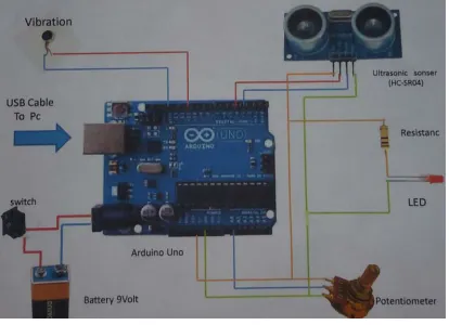
[image:8.612.92.300.229.277.2]The proposed system of the problem under consideration is shown as block diagram in figure (8) and the system hardware connection is shown in figure 8 of three main components: ultrasonic sensor [12], Arduino Uno, and alarm system.
I. II.
Figure 8. Block diagram of the proposed system
In this research, HC-SR04 module is used as ultrasonic ranging that provides non-contact measurement function of 2 cm to 400 cm. The accuracy of ranging reaches to 3 mm and effectual angle less than 15°. This module is powered by 5V power supply. Now each pin can be used as listed below:
VCC: It connects to positive voltage of 5v for power supply.
Trig: the pulse is sent to sensor for object detection in ranging mode.
Echo: echo signal is sent back if there is an object was detected or if not there is no object has been detected.
GND: Completes electrical grounded pathway of the power.
6.1. HC-SR04 Specifications
The values of HC-SR04 parameters are: DC 5 V working voltage, 15 mA working current, working frequency is 40 Hz, 4 meters as a maximum range and 2 cm minimum range, 15 degree of measuring angle, 10µs pulse width for TTL (Trigger Input Signal), the range and echo output signal are in proportion, and board dimensions of 45 x 20 x 15 mm3.
6.2. Arduino Uno
The Arduino Uno is a microcontroller board as shown in figure 9 based on datasheet of ATmega328 with practical connections. It has 14 digital I/O pins, 6 of them are used for PWM outputs, another 6 are used for analog inputs, USB
connection, power jack, ICSP header, 16 MHz ceramic resonator, and a reset button. It is supporting the microcontroller with simply connection to the computer by USB cable and power supplied with AC to DC adapter or DC battery to start.
[image:8.612.315.522.313.463.2]Microcontroller is a Tmega328 of input voltage (recommended) = 7 – 12 V, input Voltage (limits) = 6 - 20V, operating voltage = 5 V, 14 digital I/O Pins that 6 of them provide PWM output, 6 pins for analog input, 40 mA DC current per I/O Pin, 50 mA DC Current for 3.3V Pin, 32 Kbyte flash memory (ATmega328), 0.5 Kbyte is used by boot loader, 2 Kbyte for SRAM memory (ATmega328), 1 KB is used for EEPROM memory (ATmega328), clock speed of 16 MHz, structure dimensions of 53.4 mm width and 68.6 mm length, and weight of 25 g.
Figure 9. Connection of system design 6.3. Alarm System
In alarm system, a simple knob potentiometer is provided with variable resistance, to read the analog value of Arduino board. So that, this value controls the specific rate at LED blinks. Three wires were connected to the Arduino board. The first one is connected to the ground that comes from one of the potentiometer outer pins. The second wire is used to transfer 5 volts to the other potentiometer outer pin. The third wire is used for analog input 0 to the potentiometer middle pin. By turning the potentiometer shaft, the amount of resistance is changed on either side of the wiper and this wiper is connected to the potentiometer center pin. This process changes the relative closeness of that pin to the ground and 5 volts, giving different value of analog input. At turning the shaft all the way in one direction, there are zero volts passing to the pin, and 0 will be read. After that, when we turn the shaft all over the way in other direction, the 5 volts goes to the required pin and 1023 can be red. Ultras
onic Senso
Arduino and
6040 In addition, the number between 0 and 1023 is proportional to the applied voltage to the pin.
Figure 10. A photo of Practical System Design
The proposed system is implemented practically whose final circuit and connection is shown in figure 9 while figure 10 shows a photo of the implemented system.
6.4. System Software
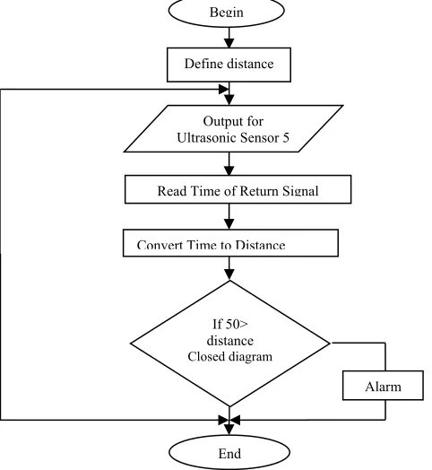
[image:9.612.62.303.428.690.2]In this paragraph, we will explain who the system work through the programing. And we show that firstly in the algorithm in Figure 11.
Figure 11. Flow chart for software processing
Time = Time/2 in µ Sec Distance = Speed + Time
= 0.0343 cm/ µ Sec * Time/2 Distance = 0.01715*Time
Distance = Time/(1/0.01715) = Time/(58.3) cm Speed = 343 m/sec
= 343*166/1000099 = 0.0343cm/ µ Sec 50>distance
7. CONCLUSINS
The blind and deaf persons are frequently suffering in mobility through indoor or outdoor fields when exercising the daily life basic things and could put their lives at risk while traveling. In my country, due to the lack of necessary equipment to provide them with assistance to avoid the daily life risk. For this reason, the idea of research was come to over this risk. The proposed design with manufacturing ultrasonic sensor handheld sensor that can detect obstacles within the wireless system designed ranges (2 cm-400 cm) to avoid and attend the blind person through the vibration device. The ultrasonic sensor system in this project is designed to alert for blind persons and deaf persons by the vibration device for alarm them when you walk a rod vibrated when approached from obstacles or when there is a risk. The proposed device has suitable great and easy used for deaf and blind person than white cane. The sufficient range of this device (50-150 cm) for this system design, and can be reached to 400 cm if they need to be worked in wide indoor distance.
8. ACKNOWLEDGMENT
The author would like to sincerely thank electrical power engineering department staff for their help to finish this work. Special thanks to Middle Technical University in Baghdad for support me to do this research.
REFRENCES:
[1] William Stallings, Cryptography and Network Security Principles and Practices, Fourth Edition, Prentice Hall, November 16, 2005.
[2] U. C. Berkeley, Advanced Computer Networks, Brighten Godfrey, 2011.
[3] Alfred J. Menezes, Paul C. van Oorschot, and Scott A. Vanstone Handbook of Applied Cryptography, Massachusetts Institute of
Technology, June 1996. Begin
Define distance
Output for Ultrasonic Sensor 5
Read Time of Return Signal
Convert Time to Distance
If 50> distance Closed diagram
End
6041 [4] Lawrence C. Washington, Introduction to
Cryptography with Coding Theory, Second Edition, Pearson Education International, Department of Mathematics, University of Maryland, 2010.
[5] JOHN F. KENNEDY, Cryptography, Fifth Edition, Chapter 5, Security Engineering: A Guide to Building Dependable Distributed Systems, 2009.
[6] Grant Gipson, How to get started with the Mifare MF522-AN and Arduino, www.grantgibson.co.uk, April 2012.
[7] Mikro Elektronika, Arduino library for MFRC522 and other RFID RC522 based modules. https://github.com/miguelbalboa/rfid, 2016.
[8] NXP Semiconductors, Standard performance MIFARE and NTAG frontend (MFRC522), Product data sheet, COMPANY PUBLIC, April 2016, http://www.nxp.com
[9] Massimo Banzi, Michael Shiloh, Getting Started with Arduino, ISBN 1-4493-6333-4, 2014.
[10] Simon Monk, Programming Arduino Next Steps: Going Further with Sketches, ISBN 978-0071830256, 2013. [11] Jack Purdum, Beginning C for Arduino: Learn
C Programming for the Arduino and Compatible Microcontrollers, 2012. ISBN 978-1430247760.
[12] Durante Gabriel Becari, Wesley Lima, Felipe A. S. Peres, Henrique E. M., "Electrical Impedance Sensor for Real-Time Detection of Bovine Milk Adulteration," IEEE Sensors Journal. Vol. 16, No. 4, pp. 861–865, February
![Figure 1. Ultrasounds are used by bats for navigation in the darkness [5]](https://thumb-us.123doks.com/thumbv2/123dok_us/8905565.956649/2.612.312.535.80.229/figure-ultrasounds-used-bats-navigation-darkness.webp)