Full Length Research Article
INTEGRATING SOIL-STRUCTURE INTERACTION ALONG BASEMENT WALLS IN STRUCTURAL
ANALYSIS PROGRAMS
1,*
Désirée Hanna Khoueiry and
2Michel Farid Khouri
1,2
Department of Civil Engineering, Branch II, Lebanese University, Lebanon
ARTICLE INFO ABSTRACT
Recent field and laboratory studies have shown that the effect of Soil-Structure Interaction (SSI) can be not conservative to a structure if not considered. In evaluating the SSI effect along basement walls on the seismic response of moment-resisting frame buildings with multiple basements, a parametric study is performed on multiple story buildings resting on flexible grounds. The number of basements is varied and UBC suggested site conditions are considered. Comparing results obtained by Plaxis that considers SSI along basement walls and Robot that consider it only at foundation level (by mean of springs), one can observe that SSI along basement walls greatly affects the seismic performance of buildings subjected to ground movements. Results obtained from Plaxis and integrated into the Robot model by means of springs along basement walls with specific extracted stiffness values proved the accuracy of the method. These stiffness values are calculated using force-displacement relationships, and charts that relate stiffness to depth of basements are generated.
Copyright © 2015Désirée Hanna Khoueiry and Michel Farid Khouri. This is an open access article distributed under the Creative Commons Attribution License, which permits unrestricted use, distribution, and reproduction in any medium, provided the original work is properly cited.
INTRODUCTION
The assumption of fixing the building at the base used in structural analysis programs, neglects the flexibility of the soil under foundation and around basements. Even though this assumption is a common practice, it has been proved that SSI could clearly affect the seismic response of the building. Khalil et al. explained that the flexibility of the soil induce an increase in the period of the structure (Khalil et al., 2006).Most building codes treat low and medium rise regular buildings with multi-level underground stories with the same recommendations used for buildings with surface foundations. The U.S. seismic regulations (FEMA 450, 2003) suggest a simplified procedure to take into account the effect of SSI. These procedures that are based on traditional expressions of SSI, assumes that the ground has a linear-elastic behavior. Other, the seismic code ATC-3-06 offers a simple formula for estimating the fundamental period and damping coefficient of a structure.
*Corresponding author:Désirée Hanna Khoueiry,
Department of Civil Engineering, Branch II, Lebanese University, Lebanon.
According to PS92, when buildings have underground stories, the code demands the use of a part of the underground height depending on the type of the foundation soil (Règles, 1995). As far as Eurocode 8 is concerned, considering the effect of soil-structure interaction is beneficial for most conventional building structures since it reduces the bending moments and shear forces in various elements of the superstructure (Eurocode, 1998). In brief, the current state-of-practice for seismic design of buildings with multiple underground stories involves approximate approaches that primarily differ according to the designer’s judgment and experience. This is a consequence of lack of relevant recommendations in building codes. However, it is important to incorporate the underground stories, basement walls, foundation soil and side soil explicitly in the mathematical model of the structure to be able to assess the actual effect of the seismic load on the building. Foundation engineers generally use Geotechnical programs such as Plaxis (Plaxis, Version 8)that take into consideration SSI, while structural engineers use programs such as Robot, (Autodesk, 2013)that do not involve SSI along basement walls in the dynamic analysis of structures. The objectives of this work is to evaluate the effects of SSI along basement walls on the seismic behavior of structures by comparing the two
ISSN:2230-9926
International Journal of Development Research
Vol. 5, Issue, 04, pp. 4061-4068, April,2015
DEVELOPMENT RESEARCH
Article History:
Received 15th January, 2015
Received in revised form 17th February, 2015
Accepted 21st March, 2015
Published online 29th April, 2015
Key words:
Soil-Structure Interaction (SSI), Basement Walls,
Seismic Behavior, Moment Resisting Frames, Base Shear,
programs and to find a procedure to integrate these effects obtained from Plaxis into structure analysis programs, such as Robot. This study will be limited to the effect of soil-structure interaction on the top displacement of the building and its fundamental frequency, noting that the soil-structure interaction is not limited to variations in the fundamental period of the structure, but has also lots of different effects.
Description of the building models
[image:2.595.79.245.342.375.2]The parametric study involves the investigation of seismic behavior of buildings with 5, 10, 15 and 20 stories with 3, 5 and 7 basements. The models adopted herein are reinforced concrete moment resisting frames of 5m spans. Each story height is 3m, the thickness of the floor was taken equal to 0.25m according to the rules of the ACI 318M-08 (American, 2008).The slabs were considered rigidly connected to the columns and the buildings were assumed to rest on a mat type foundation. The gravity loads assigned to the buildings were the dead loads consisting of the own weight of structural components, in addition to the load due to non-structural elements and the live load. These loads are presented in the Table 1.
Table 1. Gravity loads acting on the buildings
Unit weight of the concrete 25 KN/m3 Nonstructural components 5 KN/m2
Live load 2.5 KN/m3
The concrete used for structural elements has a compressive strength f'c = 25 MPa, an elastic modulus E = 32000 MPa, a shear modulus G = 13300 MPa and a Poisson's ratio equal to 0.2.The buildings site has a 35-m-thick deposit of homogeneous soil underlain by the bedrock.
The information of this layer are used to calculate the foundation’s properties and the static pressure on basement walls according to ACI 318M-08. No groundwater is considered; also the deformation modulus E and the shear modulus G of the soil are the dynamic modulus used for small deformation
(
FASCICULE, 2012; Bourgeois, 1997)
.Three soil types considered for the parametric study similar to those presented inUBC97 (Uniform Building Code, 1997):
• Soil Class C, corresponding to a very dense soil to soft rock,
• Soil Class D, corresponding to a stiff soil profile, • Soil Class E, corresponding to a soft soil profile.
Preliminary analysis of the buildings
The five, ten, fifteen and twenty story buildings were modeled using the structural analysis program ROBOT assuming fixed base condition. In order to simplify the comparison between models, column sections were not changed since the objective of this study is the seismic behavior of the building rather than its seismic design. Seismic loads are calculated using the code UBC97 (Uniform Building Code, 1997). On the other hand, the superstructure is considered to remain in the elastic range during the seismic excitation (Khouri, 2009; Khouri, 2011). The basement walls must resist the lateral earth pressure, the bending moment and shear. Table 4 provides the stiffness of columns and basement walls obtained.
[image:2.595.112.472.468.565.2]Buildings considered in this study involve different vertical loads on foundations in addition to several types of soils; this wide range of variable parameters results in different thicknesses for the mat foundation. In order to reduce the complications of the comparison process between various models, the same raft thickness was used for all buildings with the same soil class type. Consequently, the bearing capacity safety factor is higher for buildings with 5 floors and decreases by increasing the number of floors. For soil class C, a raft of 1.5m was used; also for soil class D, a raft of 1.5m was used, however the study was carried out only for 5, 10 and 15 floors and not for 20 floors; this is because the bearing capacity of the soil cannot support the loads of the 20 floors. On the other hand, the raft thickness used for soil class E was2m and buildings with 5 and 10 floors were only considered for this type of soil.
Table 5. Ultimate bearing capacity for the soil types and basements considered
Ca [kg/cm2) 3 basements 5 basements 7 basements
Soil SC 4.8 5.8 6.9
Soil SD 2.8 3.7 4.8
Soil SE 1.9 2.6 3.6
Even though the bearing capacity is important in the analysis of any structure, the effect of varying it was not significant for our study because we are mostly involved with the basement
Table 2. Soil properties
γunsat[kN/m3] γsat[kN/m3] E [kN/m2] υ (nu) C [kN/m2] φ [°] ψ [°] Vs(m/s)
SC 18 20 7.64 e+05 0.3 1 33 7 400
SD 18 19 2.057e+05 0.3 1e-3 30 20 200
SE 16 18 4.224e+04 0.3 2 24 0 100
Table 3. Parametric study Nb. Of Floors 20 15 10 5 Nb. Of Basements 3 5 7
[image:2.595.113.468.588.622.2]Soil Type SC SD SE
Table 4. Rigidities of columns and basement walls for various stories considered.
5 Stories 10 Stories 15 Stories 20 Stories Normal Rigidity [kN/ml] 8.000 e +06 8.000 e +06 9.600E+06 1.120E+07
Flexural Rigidity [kN.m2/ml] 4.167 e+04 4.167 e+04 7.200E+04 1.143E+05
[image:2.595.319.546.661.704.2]walls subjected to lateral loads. Table 5 shows the ultimate bearing capacity of each soil type for each excavation depth.
PLAXIS modeling
Literature has shown that PLAXIS software has proven its efficiency in many engineering cases for modeling SSI. Many articles address how Plaxis can efficiently be applied as a tool in seismic SSI problems (Besseling and Lengkeek, 2012). The Plaxis bulletin in many issues contains descriptions of practical projects in which Plaxis has been used for modeling SSI (Plaxis Bulletin, 2006). Plaxis performs analysis in plane strain and allows introducing the whole soil-structure system; this system is subjected to seismic excitation at the impermeable bedrock level. The linear elastic elements in PLAXIS, are represented by their normal inertia EA and bending inertia EI as “plate” elements. The load includes self-weight, superimposed dead load plus25% of the live load, and physical damping in the building and the ground is simulated by Rayleigh formula. In addition, Mohr-Coulomb was used to model the soil and the presence of groundwater is neglected.
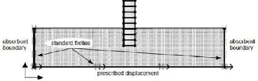
[image:3.595.317.545.405.468.2]The seismic loading was applied as a time history corresponding to a maximum seismic acceleration of 0.2g. This time history was obtained from recordings on a bedrock site made in Turkey and presented in Figure 1. The vertical limits are taken far from the building and considered as absorbent boundaries; they absorb the seismic waves and prevent their reflections in the ground, see Figure 2.The seismic excitation time was taken to be 10s for all models, and the time-displacement at the top of the building and the fundamental period obtained from PLAXIS are to be compared to the Robot Model.
Figure 1. Time history used with maximum acceleration of 0.2g
ROBOT modeling
ROBOT was used to model the structure that was assumed to be supported on elastic springs to consider flexible foundations as shown in Figure 3; Kh is the horizontal stiffness
and Kv is the vertical stiffness.
Figure 2. Boundary conditions for the basic model in Plaxis (5 floors, 3 basements)
The difference between Robot Model and Plaxis Model will only be the SSI along basement walls. The stiffness coefficients of the springs are determined from the expressions of Newmark and Resenblueth for rectangular foundations (Newmark, 1971).
Kh = 2(1+υ).G.βx√ .
Kv= v√ .
With:
L/B = 1 and (βx =1, βv = 2.16),
L/B = 2 and (βx =0.94, βv = 2.2),
L/B = 4and (βx =1, βv = 2.4),
[image:3.595.39.255.439.555.2]Where L and B are the length and width of the foundation, taken in this case equal to 1considering the rigidities per square meter of the floor. Table 6 gives the values of the spring stiffness for both directions depending on the shear wave velocities associated with the three types of soils studied. The seismic loading at the base of the building will be the amplified accelerogram obtained from a site response analysis carried out within PLAXIS at the foundation level. The time-displacement curve at the top of the building will be compared to that obtained from PLAXIS in addition to the natural frequency. Consequently, the influence of the SSI along basement walls will be the difference between the two models.
Table 6.Properties of each soil type
Soil type SC SD SE
Shear wave velocity Vs [m/s] 400 200 100
Density ρ [kN/m3] 18 18 16
Poisson's ratio υ 0.3 0.4 0.3
Kh [T/m] 76440 20572 4246
Kv [T/m] 90720 26450 5039
RESULTS AND DISCUSSION
Numerical simulations using Plaxis and Robot were made by varying the parameters of the structure and the soil (see section 2). For each combination of parameters, time-displacement curve at the top of the building was obtained; this allowed exposing the influence of SSI along basement walls on the behavior of the structure.
Case Study
For a soil type SC, twenty stories with 7 basements, the two time-displacement curves obtained from both model (Plaxis and Robot) are presented in Figure 4. Note that the periods of the 2 curves are approximately the same, but the displacement at the top of the building is a little bit larger in Plaxis than in Robot. This shows that not considering SSI along basement walls in Robot can be harmful to the building as it increases the displacement at the top of the building without changes in the fundamental frequency. On average, the ratio of frequency variation between the two models is Fplaxis/Frobot = 1.09, while
the ratio of the maximum displacement variation is
[image:3.595.36.290.654.734.2]Figure 3. Robot model for 5 floors, 3 basements
Figure 4. Time-displacement curves. (SC - 20 Stories - 7 basements)
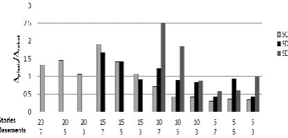
[image:4.595.48.277.458.559.2]The same curves were generated for each case study, and the ratio of the frequencies from Plaxis over that obtained from robot are presented in the chart of Figure 5. Similarly, the ratio of the displacements at the top of the building determined by Plaxis over that by Robot are presented in the chart of Figure 6.
Figure 5. Chart for the frequency ratio for all soil types
Figure 6. Chart for the displacement ratio for all soil types
Influence of SSI
To evaluate the influence of SSI along basement walls on the behavior of the structure, one needs to compare its influence
on the natural frequency of the building with its influence on the displacement at the top. The relationship between frequency and displacement ratios can be summarized as follows:
• If SSI causes an increase in frequency ratio (Fplaxis/Frobot>
1) with an increase in displacementratio (Δplaxis/Δrobot> 1),
it would be the worstcase where the SSI is harmful to the building if not considered in the model.
• If SSI causes (Fplaxis/Frobot> 1) with (Δplaxis/Δrobot< 1), this
means that the behavior of the structure has been modified, and the structure tends to behave as a rigid structure which absorbs greater forces as it moves less.
• If SSI causes (Fplaxis/Frobot< 1) with (Δplaxis/Δrobot> 1), the
SSI can be beneficialand the structure tends to behave as a flexible structure which receives less forces but the top displacement should be checked to remain within code limits.
• Finally, if SSI causes (Fplaxis/Frobot< 1) with (Δplaxis/Δrobot<
1), then SSI tends to be beneficial since it reduces the bending moments and shear forces in the superstructure thereby reducing the displacement of the building.
In the charts of Figures 5 and 6, it can be noticed that the cases where the SSI leads to (Fplaxis/Frobot>1 with (Δplaxis/Δrobot> 1) are
for buildings with high number of floors and basements and for soil type SE. For soil type SC and high number of floors, SSI has a slight influence. It is because of the ratio between the height of the superstructure divided the height of the basement is reduced which produce less lateral effects of the soil in this configuration. The same can be observed for SD soil type. In addition, from the charts, it can be observed that by decreasing the number of basements, the influence of SSI decreases for all soil types and for a small number of floors the structure is relatively rigid as it receives more forces and moves less. Consequently, it is important to incorporate the basement walls and side soil explicitly in the mathematical model of the structure in order to be able to assess the seismic effect on the underground part of the building and hence determine the actual forces acting on various structure elements. The question that arises at this stage is how to incorporate SSI into the Robot model. Following is the modeling method of the SSI by side springs with charts to calculate the lateral stiffness K of these springs. Structural engineers and designers can use these charts for proper modeling and evaluation of structures.
Method for modeling the SSI effects by lateral elastic springs
The preceding observations clearly show that the SSI along basement walls affect the behavior of the structure, and can sometimes be harmful if not considered especially for soft grounds. The question that arises is how we can integrate this effect into any structural analysis programs. Using lateral springs along the basement walls to model the soil behavior, the soil exerts compression on these walls but no tension; therefore, these springs must have zero stiffness in tension. Consequently, the springs are placed on one side of the building as in Figure 7. In this way, when the springs are compressed, they represent the resistance of the soil on one side of the building and when the springs are stretched, they represent the compression of the soil on the other side.
[image:4.595.57.266.589.689.2]Including these springs in the Robot structural model incorporates the soil effect on the basement walls obtained by the Plaxis model.
Stiffness Calculations
Using Plaxis model for the building with 20 floors and7 basements for a soil type SC, the shear curve on the walls of the 7 basements are obtained as shown in Figure 8.
Figure 7. Modeling the SSI by lateral springs
Figure 8. Shear along basement walls obtained from Plaxis for 20 floors, 7basements and soil SC
The derivative of each derivable part of the curve gives the load on the basement walls; this is dynamic earth pressure on the wall. The derivative is done by increments, according to the following formula: f’ = , where ∆V is the
shear values between two consecutive points, and difference in depth between two consecutive points. reactions of the slabs on the walls are calculated from the difference in shear force at each slab. These results can compared to the static earth pressure (P = ρ.g.h.K
presented in Figure 9. Results show that the additional dynamic earth pressure is maximum at the surface of the ground and decreases until it becomes zero at foundations as expected. This clearly explains the graph obtained. The total earth pressure is greater than the static earth pressure at the surface of the ground and increases with depth, approaching the static earth pressure. Considering slab reactions as forces on the soil from PLAXIS, the equivalent soil stiffness is deduced according to F=K.U, where K is the stiffness of the side springs. For the case under consideration which is stories, 7 basements, SoilSc), rigidities obtained are shown in Figure 10.
Including these springs in the Robot structural model porates the soil effect on the basement walls obtained by
Using Plaxis model for the building with 20 floors and7 basements for a soil type SC, the shear curve on the walls of the 7 basements are obtained as shown in Figure 8.
Figure 7. Modeling the SSI by lateral springs
Figure 8. Shear along basement walls obtained from Plaxis for 20 floors, 7basements and soil SC
The derivative of each derivable part of the curve gives the load on the basement walls; this is dynamic earth pressure on the wall. The derivative is done by increments, according to ∆V is the difference in shear values between two consecutive points, and ∆z = difference in depth between two consecutive points. The the slabs on the walls are calculated from the These results can be P = ρ.g.h.K0) and are
Results show that the additional dynamic earth pressure is maximum at the surface of the ground and decreases until it becomes zero at foundations as s the graph obtained. The total earth pressure is greater than the static earth pressure at the surface of the ground and increases with depth, approaching Considering slab reactions as forces ent soil stiffness is F=K.U, where K is the stiffness of the For the case under consideration which is (20 stories, 7 basements, SoilSc), rigidities obtained are shown in
Figure 9: Static and Dynamic Earth p for (20 floors, 7 basements,
Figure 10. Rigidity of the side springs for 20 Stories, 7 basements, and soil SC
Figure 11. Comparison of the top displacements obtained by Plaxis, Robot and Robot with Lateral
7basements and soil SC
Introducing the above rigidities into Robot
comparing in Figure 11, the displacement curves obtained at the top of the structure for Plaxis, Robot and Robot with lateral springs, it is clearly seen
structure (i.e. Robot model with side springs) converged to the results obtained by Plaxis. Also, Figure 12 shows the same graphs done for the case of 10 stories, 7 basements and soil SC. The same calculations were conducted for al
parametric variations. Rigidities obtained are presented in Tables 7,8 and 9:
Rigidity graphs
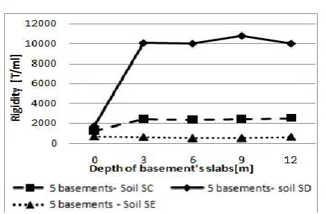
From the stiffness results, an average equivalent rigidity was calculated for each soil type and number of basements. The values are shown in the graphs of Figures 13,14and 15. Each point of these charts is the average rigidity of several models of computation from Tables 7, 8 and 9.
basements results are clear and consistent, since the soil structure influence becomes more determined
Figure 9: Static and Dynamic Earth pressure on basement walls for (20 floors, 7 basements, Soil SC)
Figure 10. Rigidity of the side springs for 20 Stories, 7 basements, and soil SC
Figure 11. Comparison of the top displacements obtained by Plaxis, Robot and Robot with Lateral Springs for 20 stories,
7basements and soil SC
Introducing the above rigidities into Robot mode land comparing in Figure 11, the displacement curves obtained at for Plaxis, Robot and Robot with lateral springs, it is clearly seen that the behavior of the structure (i.e. Robot model with side springs) converged to the Also, Figure 12 shows the same graphs done for the case of 10 stories, 7 basements and soil The same calculations were conducted for all models and Rigidities obtained are presented in
Figure 12. Comparison of the top displacements obtained by Plaxis, Robot and Robot with lateral springsfor10 stories,
7basements and soil SC Table7
Table8
Table 9. Equivalent stiffness for soil type SE [T/ml]
4066 Désirée Hanna Khoueiry and Michel Farid Khouri, Integrating soil
the top displacements obtained by
Plaxis, Robot and Robot with lateral springsfor10 stories, Figure 14. Side Springs Rigidities for 3basements Table7. Equivalent stiffness for soil type SC [T / ml]
Table8. Equivalent stiffness for soil type SD [T/ml]
Table 9. Equivalent stiffness for soil type SE [T/ml]
Désirée Hanna Khoueiry and Michel Farid Khouri, Integrating soil-structure interaction along basement walls in structural analysis programs
Figure 14. Side Springs Rigidities for 3basements
[image:6.595.64.548.373.701.2]Figure15. Side Springs Rigidities for 5 basements
Figure 16. Side Springs Rigidities for 7basements
Conclusions
In this study, the impact of the soil-structure interaction along basement walls on the dynamic behavior of the structure was investigated. The seismic behavior of buildings with multiple stories and underground stories examined and three soil types considered for the parametric study similar to those presented in UBC97. The work steps that were done can be presented as follows:
• A model was generated by Robot taking into consideration that the foundation was sitting on flexible soil.
• A model was generated by Plaxis to evaluate the SSI; the model was in Plane strain for the soil section and 2-D for the structure.
• Comparison was made between the two models Robot and Plaxis for the top displacement and the natural frequencies of the structures. Results showed that not including the effect of the basement walls surrounding soil can generate a large error in the analysis.
• Values for the equivalent stiffness K were determined from Plaxis using the force-displacement relationships and integrated into Robot to incorporate the effect of the soil surrounding the basement walls of the structure.
• The results of the SSI modified Robot model that incorporates the basement walls surrounding soil proved to be very close to the results obtained by Plaxis when compared for the top displacement and the natural frequency.
• After having a match between the results of the two model (Robot vs. Plaxis), a parametric study was performed to
determine the values of K and graphs were generated as a function of the basement depths.
• These K graphs allow structural analysts to use in their programs (any structural analysis program) to incorporate the SSI generated by the basement surrounding soils.
The findings can be summarized as follows:
• Results indicate that SSI can considerably affect the seismic response of buildings.
• It was found that the SSI effect was most critical for buildings with high number of floors and basements surrounded by soil type SE. For soils SD and SC, the SSI can change the behavior of the structure and the load path in structural elements especially for low and medium rise buildings.
• Making use of these stiffness values can make the structural analysis more accurate and close to the actual behavior of structures.
• This method allows the evaluation of the dynamic behavior of the structure, but gives no results regarding the behavior of the basement walls.
• More research need to be done to validate this work with 3D studies in order to obtain a complete modeling method that can be recommended and used not only in various structural analysis programs but also in different seismic codes.
Finally, this paper presents an analysis technique that allows the proper evaluation of structures with multiple basements situated in seismic zones. Analysis and designers that use structural analysis programs such as Robot can utilize the outcome of this work to incorporate the SSI into their designs.
Acknowledgements
The authors thanks Optimal Engineering Consulting and Contracting for sponsoring the major part of this work and special thanks to the Lebanese University, Faculty of Engineering, Branch II and École Doctoral des Sciences et de Technologie for sponsoring part of this on-going research.
REFERENCES
American Concrete Institute. 2008. ACI 318-M08 Building Code Requirements for Structural Concrete, Detroit. Autodesk Robot Structural Analysis Professional 2013. Besseling, F., Lengkeek, A. 2012.Plaxis as a Tool for
Soil-Structure Interaction Modeling in Performance-Based Seismic Jetty Design, WitteveenandBos., The Netherlands. Bourgeois, C. 1997. Module de Cisaillement à Petites
Déformations des Argiles Champlain, Université Laval, Quebec.
Eurocode, 2005. 8. Calcul des structures pour leur résistance au séisme, NF EN 1998.
Khalil, L., Sadek, M. and Shahrour, I. 2006. Influence de l’Interaction Sol-Structure (ISS) sur la Fréquence fondamentale des bâtiments (USTL), Laboratoire de Mécanique de Lille (CNRS UMR 8107), Université des Sciences et Technologies de Lille (USTL), Polytech-Lille – 59 655 Villeneuve d’Ascq cedex.
Khouri, M. F. 2011. Drift limitations in a shear wall considering a cracked section, AES Technical Reviews
Int.J., part D, IJRSESS, 1(1), 31-38.
Khouri, M.F. 2009. Estimation of the Maximum Allowable Drift at the Top of a Shear Wall (within Elastic Limits). In Proceedings of the 7th World Conference on Earthquake Resistant Engineering Structures, Cyprus, Vol. 104, WIT Press, Boston, 115-126.
Newmark, N. M. and Rosenblueth, E. 1971.Fundamentals of Earthquake Engineering, Prentice-Hall, New Jersey. Plaxis 2D, version 8.
Plaxis Bulletin, 2006. Modeling passive earth pressures on bridge abutments for nonlinear Seismic Soil - Structure interaction using Plaxis, Amsterdam, The Netherlands, issue 20.
Règles, P.S. 1995. 92. Règles Para Sismiques applicables aux bâtiments, NF P 06-013, France.
Uniform Building Code, 1997.Volume 2 – Page 2-30 – Table 16J. International Council of Building Officials, Whittier -California, 1997.