ISSN: 1992-8645 www.jatit.org E-ISSN: 1817-3195
CATENATED OFDM MODULATION SCHEME
COLLABORATIVE WITH VLC FOR UPLINK LIFI SYSTEM
1
N. M. NAWAWI, 2ANUAR M. S., 3M. N. JUNITA, 4A. K. RAHMAN, 5S. A. ALJUNID
1,2,3,4,5
Optical Research Group, Advanced Communication Engineering Centre of Excellence (ACE-COE),
School of Computer & Communication Engineering, Universiti Malaysia Perlis (UNIMAP), 02600 Perlis,
Malaysia.
E-mail: [email protected]
ABSTRACT
This paper focus on performance of a new modulation approach which is known as catenated orthogonal frequency division multiplexing (C-OFDM) integration with visible light communication (VLC) system suggested for uplink LiFi system. OFDM based network modulation and demodulation have a huge comparative advantages over other modulation including reduced frequency selectivity fading, provision for a higher number of subcarriers, high data rate and higher spectrum efficiency. By using simulation, the
proposed system based on novel C-OFDM gives a good bit error rate (BER) performance (10-9 and below)
with 16-quadrature amplitude modulation (16-QAM). In term of spectral efficiency, the system is compared with presence dense wavelength division multiplexing (DWDM) technique when varied the number of users. The result reveals that proposed C-OFDM is feasible for multiband modulation system and the scheme also effects on high spectral efficiency with spectral offset of more than 1 bps/Hz compared to conventional method.
Keywords: Catenated OFDM (C-OFDM),Visible Light Communication (VLC), OFDM, Modulation Technique, Multiband Modulation
1. INTRODUCTION
Recently, researchers have shown an increased interest in Visible Light Communication (VLC) technology as its give an alternative solution where
radio frequency (RF) and infrared (IR)
communication faces limitations especially in environmental settings [1-3]. Therefore, these systems will receive acceptance for use in hospitals, private homes, etc. No interference with RF based systems exists, so that the use in airplanes as well as in oil & gas venue are uncritical. Furthermore, as light waves do not penetrated opaque objects, they cannot be eavesdropped. It is very difficult for an intruder to (covertly) pick up the signal from outside the room [4,5]. Apart from its general purpose for illumination, the VLC system that uses visible lights have also been proved for data transmission. The visible light is the form in which electromagnetic radiation covers wavelengths range from 380 nm to 750 nm. Since visible light is used and not RF waves that can penetrate walls, the issue of security is inherently solved because light cannot leave the room, containing data and information in one location. Moreover, the bandwidth of VLC
spectrum is much larger than the radio frequency bandwidth, which ranges from 3 kHz to 300 GHz [6].
With a huge bandwidth it is possible to accommodate more users and potentially achieve higher data rates because each user can be given a larger portion of the bandwidth to transfer information. One of the most significant current discussion in visible light technology is modulation types [7-9]. In VLC system, OFDM is an attractive modulation technique to achieve future optical
wireless applications demands for gigabit
ISSN: 1992-8645 www.jatit.org E-ISSN: 1817-3195 A subset of VLC system is called LI-FI (Light
Fidelity) that proposed by Professor Harald Haas. It refers to 5G Visible Light Communication systems using Light Emitting Diodes (LEDs) as a medium to high-speed communication in a similar manner as WI-FI. LI-FI uses white LED bulbs at the downlink transmitter [10]. For the duplex VLC communication, the system is commonly used RF based networks for uplink. As described earlier, RF based network has drawback due to some equipments that is prone to interference with radio waves, so by using proposed C-OFDM VLC method potentially has many advantages in this area.
It appears from the aforementioned findings that numerous research have been studied in VLC area based on theoretical and experimental [7,8,15]. Yet, very few studies have examined OFDM-VLC using simulation design. The main goal of this paper is to study and investigate the combination of visible light environment with new proposed C-OFDM modulation technique using 16-QAM data coded via a comprehensive optical tool called Optisystem software.
The rest of this paper is organized as follows. In Section 2, the performance analysis is presented, followed by C-OFDM VLC system model in Section 3. The simulation parameters and results is discussed in Section 4 and finally, the paper is concluded by Section 5.
2. PERFORMANCE ANALYSIS
In the analysis of C-OFDM VLC, other than thermal noise we have also considered the signal and ambient light noise as accumulated noise variance in the system.
At the transmitter, the serial input data stream in QAM modulation format is shifted into parallel format. The parallel data is then mapped and transmitted by assigning one symbol for each carrier. An inverse Fourier transform is performed into mapped spectrum to find the corresponding time waveform. To make sure any multipath interference not affected the orthogonality of the data channels, the cyclic prefix (guard period) can be added at the beginning of each symbol. Finally, the parallel data is shifted back into the serial symbols which is called OFDM signals.
The IFFT modulated baseband OFDM signal is represented as
1
( 2 ) 0
( )
sc
k N
j f t
B k
k
s t
c e
π−
=
=
∑
(1)where ckis the OFDM information symbol, fk is for
the subcarrier frequency at k=0, ..., Nsc-1 and Nsc is
the number of subcarriers.
The C-OFDM signals of n band can be written
as 2 1
( )
( ).
.
sb m Nj nf t
cat B n
n
s t
s t
m e
π=
=
∑
(2)1 2 2 0 1
( )
.
sc sb k m N Nj f t j nf t
cat k n
k n
s t
c e
πm e
π−
= =
=
∑
∑
(3)mnis the the modulation index of the nth subband,
while n is number of band at n=1, ..., Nsb and fm is
the sub-band frequency or also known as center frequency of first band. It calculated using
n m
f
=
nf
and listed as in Table 2. Here, weassume that the modulation index is identical for all the sub-bands [11], thus
1
0
nsb
m
N
<
≤
(4)At the receiver, the detected photocurrent is express as 1 2 2 0 1
. .
.
sc sb k m N Nj f t j nf t
r r k n
k n
I
R P
c e
πm e
π−
= =
=
∑
∑
(5)where R is the responsivity of the photodetector and
Pr is the incident light power at the receiver. The
signal to noise ratio (SNR) is given by
2 2 r Total
I
SNR
σ
=
(6)For the noise variances, we only consider shot noise and thermal noise as can written in equation (7).
2 2 2
Total shot thermal
σ
=
σ
+
σ
(7)The major noise sources present in an indoor
VLC system include ambient light noise
ISSN: 1992-8645 www.jatit.org E-ISSN: 1817-3195 solar radiation and incandescent lamps represents
essentially a DC interference that could be easily eliminated using an electrical highpass filter. The noise induced by fluorescent lamps needs to be determined in different application scenarios based on what kind of driving circuit is used [15-19]. The signal and ambient light induced shot noise usually has the form of
2
_ 2
2 (
)
shot
e I
rI
r ambientI B
σ
=
+
2
_ 2
2
2 (
)
shot
eI B
re I
r ambientI B
σ
=
+
(8)where e is the electron charge which equal to
19
1.6 10x − C, Irand Ir_ambient are the generated signal
and ambient currents in the photodetector, and I2is
the noise bandwidth factor.
Thermal noise power in the load resistance
1030
L
R = Ω is given by
2
4
thermal LkTB
R
σ
=
(9)T is anabsolute temperature (T = 300 K), k is the
Boltzmann’s constant (
k
=
1.38 10
x
−23J K
/
), and Bis the receiver bandwidth. In this paper we assume only shot noise and thermal noise that contribute total noise variance. By substitute the Equation (5) and (7) in (6) so the signal to noise ratio of the system can be written as,
1
2 2 2
0 1
1
( 2 ) 2
_ 2
0 1
( . . . )
4
2 ( . . . ) 2 ( )
sc sb
k m
sb
k m
N N
j f t j nf t
r k n
k n
N N
j f t j nf t
r k n r ambient
k n L
R P c e m e SNR
kTB e R P c e m e B e I I B
R π π π π λ − = = − = = = + +
∑
∑
∑
∑
(10)The proposed system consist of catenated OFDM model with M-ary QAM in each subchannel. Thus, the bit error rate (BER) can be obtained from SNR as below:
(
2)
2 3log 1 2 1 log M M
BER erfc SNR
M
M M
− =
− (11)
for M=4, Eq. (11) reduces to be BER for QPSK [12]:
(
)
0.5
BER= erfc SNR (12)
Where error function erfc(x) can be define as [11]:
2 0 2 ( ) x t
erfc x e dt
π
−
=
∫
(13)3. CATENATED OFDM VLC SYSTEM MODEL
Future telecommunication systems must be spectrally efficient to support a number of high data rate users. For all of the above reasons, OFDM has already been accepted by many of the future generation systems. At a very high data rate, the required electrical bandwidth also would be wider and is not cost-effective to implement even with the
best commercial digital-to-analog converters
(DACs) and analog-to-digital converters (ADCs) in silicon integrated circuit (IC) [20]. Thus, C-OFDM is proposed to fully utilized the available electrical bandwidth by adding more OFDM signals in RF domain. Instead of having high spectral efficiency, the C-OFDM also have a great capacity to
accommodate exponential growth in
communications mainly for internet users.
C-OFDM VLC system model presented in this paper consist of several users that contain of OFDM data with their representative center frequencies as in Table 2. Each user occupies maximum bandwidth of 2 GHz thus equivalent to 20 GHz passband bandwidth can accommodate five different users or data at 10 Gbps bit rate. The advantage of this technique that utilized multiple band concept allows several data to be process over a smaller bandwidth, by that the complexity of overall system design can be reduced as well as improved the spectrum efficiency and worldwide compliance.
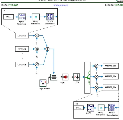
Figure 1 depicts the block diagram of the C-OFDM visible light communication transceiver system using broadband light source at 480 nm. Firstly, the binary data is encoded by QAM generator with M-ary electrical signals as the I and Q inputs for OFDM modulator. OFDM modulator which then modulates a digital signal into multiple orthogonal subcarriers. Several users have been used and each user carry one OFDM band.
Quadrature modulator at center frequency, fm were
ISSN: 1992-8645 www.jatit.org E-ISSN: 1817-3195
Parameters Value
Number of Subcarriers 512
Total number of IFFT/FFT points 1024
Position array 256
Data modulation format on all subcarriers 16-QAM
Sample per bit 4
Sequence Length 16384
Number of samples 65536
VLC distance 3m
Bit Rates 1Gbps, 5Gbps and 10 Gbps
(i)
[image:4.612.86.517.64.482.2]Light Source
Figure 1: C-OFDM Visible Light Communication Transceiver Design Simulation (i) Transmitter part. (ii) Subset of Receiver Part
(ii) DATA
QAM OFDM Demodulator M-ary
Subsystem VLC PIN
DATA 1
OFDM Modulator QAM
Generator
M-ary Subsystem
OFDM 2
OFDM n
. . .
OFDM 1
f1
f2
fn
OFDM_Rx _ n OFDM_Rx _ 2 OFDM_Rx _ 1
f1
f2
fn (i)
[image:4.612.127.485.559.673.2]ISSN: 1992-8645 www.jatit.org E-ISSN: 1817-3195 The proposed model is suggested for indoor uplink
Li-Fi system, thus the VLC distance is in range of 3 m be analyzed using visible laser light (VLD) source. Attenuation and other losses in VLC channel are assumed to be zero.
The receiver architecture displays in the inset (ii) of Figure 1. OFDM_Rx is a set of demodulators contain of QAM demodulator and OFDM demodulator which translate every carrier down to direct current. The signal is integrated with the symbol period to regenerate the data from that carrier. The same demodulator also demodulates the other carriers. As the carrier spacing equal to the reciprocal of the symbol period means that they will have a whole number of cycles in the symbol period leads to no interference contribution.
4. SIMULATION PARAMETERS AND RESULTS
Simulation were performed based on parameters stated in Table 1.
Each subcarrier of OFDM signal encoded with 4-QAM symbol and generated at a center frequency as shown in Table 2 for each user. The received
electrical C-OFDM signal bands after
optical/electrical (O/E) conversion shown in Figure 2(b) has a similar pattern to the input signal before MZM (Figure 2(a)). In OFDM system it is necessary for a receiver to be able to receive the whole transmitted signal. Even though the sidebands from adjacent carrier overlap to each other, they can still be detected without interference because the orthogonality concept they are adopted. This is achieved by having the carrier spacing equal to the reciprocal of the symbol period.
Figure 2 prove that the proposed design is successfully demodulated the input data due to accurate design system by assigned a suitable parameters for transmitter and receiver module. Each user is centered at their frequency and every
band is catenated to each other. Notably,the power
intensity of C-OFDM signals after PIN detection is below -50dBm compared to 0dBm before modulator is due to transmission penalty of the system. Transmission penalty can be reduce by placing amplifier between transmitter and receiver, however in this paper we are not include any power booster into the design. This finding provides evidence that the C-OFDM scheme can be alternative choice for modulation technique as it
can transmit more users at a same time with only one carrier light source. We evaluate the free space visible light channel at 3m room distance at 1Gbps, 5Gbps and 10 Gbps bit rate.
Table 2: Center Frequency For Each User
User Number Center Frequency
(GHz)
User 1 3.7
User 2 7.4
User 3 11.1
User 4 14.8
User 5 18.5
(a)
[image:5.612.318.515.274.703.2](b)
Figure 2: Electrical Spectra Of C-OFDM Signal Bands. (a) Before Modulator. (b) After PIN detection.
ISSN: 1992-8645 www.jatit.org E-ISSN: 1817-3195
4.1 BER Performance Analysis
We first examine the influence of the proposed system scheme on performance affected by different bit rate and number of user. Figure 3 shows the error rate performance evaluated at range of effective power level for 1 Gbps, 5 Gbps and 10Gbps. At BER of 10E-9, the photodetector sensitivity for 10 Gbps and 5 Gbps are at - 13 dBm and -18.5 dBm respectively. However, for 1 Gbps bit rate, the minimum effective power is much lower than -22 dBm. As can be seen the lower the bit rate, less bit errors has occurred. The power penalty loss is about 5.5dB when we decrease the bit rate from 10Gbps to 5Gbps in the same environments. Between 10Gbps to 1 Gbps the penalty loss is higher than 9dB. This graph proved that our proposed design working well at very high bit rate at 10 Gbps. Therefore in Figure 4, we analyzed BER against effective power simulated with various number of user for system running at 10 Gbps.
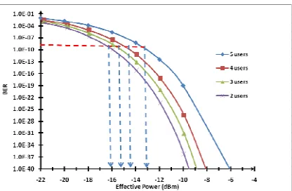
In Figure 4, the number of user (2 users) is defined as two bands (1st and 2nd band) of the C-OFDM signals which are catenated to each other. Likewise, 3 users are defined as three bands (1st, 2nd and 3rd band) of the C-OFDM signals are catenated together. Hence, for 3 and 4 users are defined correspondingly. It is obviously in Figure 4, the error floors for 2, 3, 4 and 5 users have a similar pattern degradation for BER graph. BER is decreases with the increase of effective power. At
BER = 10-9, the required effective power is -16dBm
for the case of 2 users use in the proposed scheme which is much less than -13dBm for the case of 5 catenated users at same level of BER. Thus the power penalty loss here is 3 dB when we increased the number of user from 2 to 5 in C-OFDM method. As the number of user increase, the needed bandwidth to accommodate the user will also increase. As can be seen in Equation (8) and (9), the noise power is proportional to the bandwidth. Thus, the wider the bandwidth, the bigger the noise power. It leads to lower signal to noise ratio and
caused the BER reduction as illustrate
mathematically in Equation (10) and (11). In Figure 4, the BER is degrade with increase the number of users and the value is highest for 5 users but the minimum detectable power for this case is below than -13dBm and is acceptable. So, we can conclude that the proposed system is feasible and give good performance at very high bit rate which suitable to be implemented for uplink Li-Fi system.
Figure 3: BER Against Effective Power Simulated With Different Bit Rate Of 5 Users.
Figure 4: BER Against Effective Power Simulated With Various Number Of Users.
4.2 Comparison the Proposed Scheme with Parallel Multiband Scheme (DWDM)
In this section, the proposed design is compared to conventional multiplexing method, DWDM based on their spectral efficiency. The simulation context for the traditional DWDM is using OFDM modulation for DWDM VLC system. In this simulation, the simulation parameters are same as in Table 1 and the spectral width between the adjacent channels is fixed to 0.2 nm. The number of channel/user is set to 2 to 5 as C-OFDM VLC scheme.
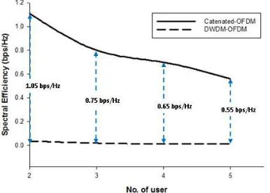
Figure 5 illustrate the bandwidth efficiency
comparison between proposed scheme and
DWDM-OFDM simulation environment. It can be seen from the figure, the spectral efficiency remained constant at 0.05 bps/Hz for various number of users in the case of conventional
DWDM-OFDM scheme. Compared to the
traditional scheme, the proposed technique obtains the spectral efficiency of 1.1 bps/Hz for 2 users. This gives the efficiency gap approximately to 1.05 bps/Hz which is the largest improvement compared to 5 users with offset = 0.55 bps/Hz.
[image:6.612.301.524.77.207.2] [image:6.612.314.522.236.372.2]ISSN: 1992-8645 www.jatit.org E-ISSN: 1817-3195 The relation between spectral efficiency and bit
rate is written in equation below:
_
,
R
Spectral eff
B
η
=
(14)
where R is a bit rate and B is the bandwidth.
Here, we can conclude that the C-OFDM VLC design has a higher spectral efficiency than conventional DWDM-OFDM VLC under the same
communication conditions. It shows that
[image:7.612.97.290.340.478.2]conventional DWDM-OFDM scheme needs higher bit rate to performed at same spectral efficiency. However, in free space visible light environment, limitations that author have to count include noise from ambient lights and the light-of-sight of the system. To compensate for these, in our design simulation, the transmitter and receiver are facing directly to each other.
Figure 5: Spectral Efficiency Against Number Of Users For C-OFDM VLC And DWDM-OFDM VLC System.
5. CONCLUSION
An analytical and simulation performance analysis of novel 16-QAM C-OFDM in VLC channel for Li-Fi indoor uplink application is presented in this paper. In contribution to this work, C-OFDM improve the conventional DWDM-OFDM VLC scheme. At 10 Gbps bit rate, this proposed scheme can accommodate up to 5 users
with effective power of -13dBm at BER of 10-9. As
addition, this approach can be alternative for multiband modulation as it is fully utilized the given baseband bandwidth. Therefore, the C-OFDM can enhanced the performance of VLC which can carry more user at the same time with acceptable BER. The simulation analysis has shown that the C-OFDM scheme can offer higher spectrum efficiency compared to DWDM-OFDM technique in term number of users. This work can
be a future guide to more intensive research on high data rate system, complex OFDM modulation and also visible light communication system by promising solution for high capacity transmission and high spectral efficiency network. Future research and development will be directed toward further system optimization and evaluating the presence of noises in the VLC system.
REFRENCES:
[1] Khalid, A. M., et al. "1-Gb/s transmission over a phosphorescent white LED by using
rate-adaptive discrete multitone modulation."
Photonics Journal, IEEE 4.5 (2012): 1465-1473.
[2] Wu, Zeyu, Jimmy Chau, and Thomas Little. "Modeling and designing of a new indoor free
space visible light communication
system." Networks and Optical
Communications (NOC), 2011 16th European Conference on. IEEE, 2011. [3] Uddin, Muhammad Shahin, et al. "Mitigation
technique for receiver performance variation of
multi-color channels in visible light
communication." Sensors 11.6 (2011):
6131-6144.
[4] H. Elgala, R. Mesleh, H. Haas and B.
Pricope, "OFDM Visible Light
Wireless Communication Based
on White LEDs”, Proc. of IEEE, 2007.
[5] Lee Chia Ching, Tan Ching Seong and Wong
Hin Yong of Multimedia University
and Mazlaini Yahya of TM
Innovation Centre TEEAM, 60th
Diamond Jubilee ISSUE.
[6] The Electrical and Electronics Association of Malaysia http://www.teeam.org.my/
[7] Afgani, Mostafa Z., et al. "Visible light
communication using OFDM. "Testbeds and
Research Infrastructures for the Development of Networks and Communities, 2006. TRIDENTCOM 2006. 2nd
International Conference on. IEEE, 2006. [8] Lee, S. C. J., et al. "Discrete multitone for
novel application areas of optical
communications." 2008 Digest of the
IEEE/LEOS Summer Topical Meetings. 2008. [9] Zheng, Yueqiao, and Minglun Zhang. "Visible light communications-recent progresses and
future outlooks." Photonics and
Optoelectronic (SOPO), 2010
Symposium on. IEEE, 2010.
ISSN: 1992-8645 www.jatit.org E-ISSN: 1817-3195 [11] Mohd Nordin, Junita, et al. "Performance
evaluation of broadband access network based on subcarrier multiplexing (SCM): Spectral amplitude coding optical code division
multiple access." (2013).
[12] Wang, Yiguang, et al. "High speed LED based visible light communication networks for
beyond 10Gb/s wireless access.
"Wireless Communications and Signal
Processing (WCSP), 2014 Sixth International Conference on. IEEE, 2014.
[13] Van Wyk, Jacques H., and Louis P. Linde. "Bit error probability for a M-ary QAM
OFDM-based system." AFRICON 2007. IEEE, 2007.
[14] Vucic, Jelena, and Klaus-Dieter Langer. "High-speed visible light communications:
State-of-the- art." Optical Fiber Communication
Conference. Optical Society of America, 2012. [15] Duan, Jingyuan, Ancun Shi, and Yuliang Liu.
"A practical indoor visible light
communication system." Communication
Systems, Networks & Digital Signal
Processing (CSNDSP), 2014 9th
International Symposium on. IEEE, 2014.
[16] Komine, Toshihiko, et al. "Adaptive
equalization system for visible light wireless
communication utilizing multiple white
LED lighting equipment." Wireless
Communications, IEEE Transactions on 8.6 (2009): 2892-2900.
[17] Komine, Toshihiko, et al. "Fundamental
Analysis for Visible-Light Communication
System using LED Lights." IEEE
Transactions on Consumer Electronics,
Vol. 50, No. 1, FEBRUARY 2004.
[18] Ab-Rahman, Mohammad S., et al. "Analytical Study of Signal-to-Noise Ratio for Visible
Light Communication by Using
Single Source." Journal of Computer
Science 8.1 (2012): 141.
[19] Cui, Kaiyun, et al. "Line-of-sight visible light
communication system design and
demonstration." Communication
Systems Networks and Digital Signal
Processing (CSNDSP), 2010 7th
International Symposium on. IEEE, 2010.
[20] Yang, Qi, et al. "Experimental demonstration