File No. 2780-09 Order No. GA27-3005-3
Systems Reference Library
Component Description:
IBM 2780 Data Transmission Terminal
This Component Description manual describes the principles of operation of the IBM 2780 Data Transmission TerminaL The data-link control characters, code structures, timeouts, and throughput rates associated with the Binary Synchronous method of transmission are described.
The communications facilities, data sets, and special features available for this teleprocessing terminal are also discussed. For an introduction to the Binary Synchronous method of trans-mission, refer to the manual, General Information--Binary Synchronous Communications, GA27-3004.
Additional information on the Binary Synchronous method of transmission when using an IBM 2701 or IBM 2703 can be found in the following publications:
• IBM 2701 Data Adapter Unit--Component Description, GA22-6864
2780 SRl Publications Availability Guide Use this guide to detennine what available publications will best fulfill your individual requirements.
TP SRL Bibliography
GA24-3089
I
General Info. TP System Summary Binary Synch. BSCCommunications
Infonnation
GA27-3004 GA24-3090
I
Component Physical Planning DescriptionGA27-3005
I
Physical Planning IBM 1443 Printer, Models 1, 2, andNl--IBM 1445 Printer, Models 1
GA27-3006 and Nl
GA24-3120
Template
GX27-2900
Fourth Edition (August 1971)
DOS BTAM GC30-5001 Programming Infonnation DOS OT AM (MCP) GC30-5004 OS BTAM GC30-2004 OS OTAM (MCP) GC30-2005 OS RJE GC30-2006
This is a major revision of, and obsoletes, GA27-3005-2 and Technical Newsletters N27-3039, GN27-3045, and GN27-3057. Significant modifications include a change to the machine throughput formula, the addition of information on punching and inserting the carriage tape, and an updating of the programming considerations for various error responses. A more detailed summary of the significant modifications may be found in the "Summary of Amendments" following the tables of contents and illustrations. These and other changes to the text and small changes to the illustrations are indicated by a vertical line to the left of the change.
Changes are periodically made to the information herein; before using this publication in connection with the operation of IBM systems or equipment, refer to the latest SRL Newsletter for the editions that are applicable and current.
Requests for copies of IBM publications should be made to~your IBM representative or to the IBM branch office serving your locality.
PREFACE
The purpose of this manual is to inform the reader of the functional and operating characteristics of the IBM 2780 Data Transmission Terminal. This manual was written for the system analyst who requires machine throughput knowledge; for the programmer who needs information on line responses, line-buffer capacity, and the number of records allowed per data block; and for the operator who needs to know the operating, error-recovery, and functional character-istics of the IBM 2780 Data Transmission Terminal.
The manual also contains information on timeout controls, operating characteristics of special features, information on code structures, and an explanation of data-link-control characters.
For a more in-depth understanding of the data-link and end-to-end control characters used by the 2780, the reader should be familiar with the principles involved in the Binary Synchronous method of
communication. Manuals providing this BSC (Binary Synchronous Communication) information and other information related to the IBM 2780 are indicated in the Publications Availability Guide.
CONTENTS
mM 2780 DA TA TRANSMISSION TERMINAL Introduction
2780 Models
Functional Units of the 2780 Terminology
Communications Facilities Code Structures
Card Read/Punch
Basic Operation--Card Read/Punch Reader and Punch Checking Buffers and Control Circuitry
Line Buffer I/O Buffer Buffer Operation Buffer Checking Printer
Character Sets Tape- Controlled Carriage
Carriage-Control Tape Paper Forms
Carriage Controls and Switches
Component Selection, Basic Terminal (Contention)
DATA-llNK AND END-TO-END CONTROL CHARACTERS Data-Link Control Characters
SYN (Synchronous Idle) ENQ (Enquiry) S TX (Start of Text)
11'8 (Intermediate Block Check) E1'8 (End of Transmission Block) ETX (End of Text)
DLE (Data-Link Escape)
ACK 0 and ACK 1 (Positive Acknowledgment) RVI (Reverse Interrupt)
NAK (Negative Acknowledgment)
WACK (Wait Before Transmit - Positive Acknowledgment) EOT (End of Transmission)
End-to-End Control Characters ESC (Escape)
HT (Horizontal Tab) EM (End of Media) BEL (Bell) SUB (Substitute) DEL (Delete) Transmission Checking
Redundancy Check Format Check Odd/Even BlockCotmt I/O and Buffer Check Timeout Controls
One-Second Timeout Two-Second Timeout Three-Second Timeout
Extended ENQ Retry Feature (48-second Timeout) Standard 2780 Operation
2780 Operation with Extended Enquiry Retry Transmission Feature Installed
7 7 7 7 7 7 9 9 10 16 18 18 18 19 • 20 • 20 • 20 • 21 • 22 • 24 • 24 • 26
29 • 29 • 29 • 29 • 29 • 29 • 29 • 29 30 • 30 30 31 31 31 31 • 31 • 32 • 32 33 34 34 34 34
• 36 • 36 37 .. 37 38
• 38 • 38 • 38 • 38
38
OPERA TOR CONTROLS
Card Read/Punch Controls (Models 1, 2, and 4) Switches
Keys
Indicator Lights
Printer Controls (Models 1 and 2)
Keys
Indicator Lights Printer Controls (Model 3)
Additional Switches, Keys, and Lights
SPECIAL FEA TURES Multipoint Line Control
Polling
Responses to Polling Selection
Responses to Selection Printer Horizontal Format Control Synchronous Clock
Auto Answer (Dial-Up Operation Only)
Mode Switch of Called Terminal Set to Receive Mode Switch of Called Terminal Set to Transmit Multiple- Record Transmission
EBCDIC Transparency A uto Turnaround Terminal Identification
Dual Commtmications Interface 120-Character Print Line 144-Character Print Line Selective Character Set
EBCDIC Code Six-Bit Transcode USASCII Code World Trade Features
IBM 27.80 DA TA-LINK CONTROL FORMA T Basic Line Control
Serializer Synchronization
Format, Responding to Transmission of Test Format, EOT Response or Incomplete Transmission Format, ExTor Conditions
Format, Retransmission
OPERA TING PROCEDURES
Off- Line Operation (Models 1 and 2 Only) Normal Stops
Transmit Operation (Models 1, 2, and 4) Normal Stops
Receive Operation
Normal Stops (Punch Operation) Alternate Transmitting and Receiving
(Models 1, 2, and 4)
ERROR- RECOVER Y PROCEDURES
Summary of Responses to ExTors NAK
EOT STX, ENQ ENQ 39 39 39 40 41 43 44 44 45 45 47 47 47 47 47 47 48 . 4 8 . 4 8 • 49 • 49 50 • 51 • 52 52 53 53 53 53 53 53 53 53 55 55 55 55 56 56 57 59 59 • 59 • 59 • 59 • 60 • 60
Enor-Recovery Procedures for Terminal Operator 63 ENQ Received within Text 65
Suggested Programming Considerations for the Various Error Odd/Even Block-Check Failure 65
Responses when Operating with a CPU 63
APPENDIX
NAK 63 77
EaT Response Received by CPU to a Transmitted Block 64 GLOSSARY OF TERMS 81
STX, ENQ Received by CPU from 2780 65 INDEX 83
ILL USTRA TIONS
~ Title Page Figure ~ Page
1 ffiM 2780 Data Transmission Terminal 8 17 Tape Punch 24
2 Data Flow, Terminal-to-TerminalOperation 8 18 Tractor Feed 25
3 Data Flow, Terminal-to- Computer Operation 8 19 Printer Right-Hand Controls 25
4 Six-Bit Transcode Character Assignments 10 20 Printer Left- Hand Controls 26
5 EBCDIC Character Assignments 11 21 Code Representation of DLE Character for Each Code 31
6 USASCII Character Assignments 13 22 Code Representation of RVI for Each Code 31
7 Throughout Formula 14 23 ESC Sequences and Tape Punching for a Typical
8 mM 2780 Card Reader Approximate Throughput Application 33
Rate-- Dial Line 15 24 Card Read/Punch Operator Panel (Models 1, 2,
9 IBM 2780 Card Reader Approximate Throughput and 4) 39
Rate--Four- Wire Leased Line 16 25 Printer Operator Panel (Models 1 and 2) 44
10 mM 2780 Card Punch Approximate Throughput 26 Printer Operator Panel (Model 3) 45
Rate-- Dial Line 17 27 Typical Horizontal-Format-Control Operation 49
11 ffiM 2780 Card Punch Approximate Throughput 28 Error Recovery Procedures-- Transmitting Terminal
Rate--Four- Wire Leased Line 18 Operator (2780-to-2780 Operation) (2 Parts) 66
12 ffiM 2780 Card Feed and Punch Schematic 19 29 Error Recovery Procedures--Receiving Terminal
13 mM 2780 Printer Approximate Throughput Operator (2780-to-2780 Operation) (3 Parts) 68
Rate-- Dial Line 21 30 Error Recovery Procedures-- Transmitting Terminal
14 mM 2780 Printer ApprOXimate Throughput Operator (2780 Transmitting to CPU) (2 Parts) 71
Rate--Four- Wire Leased Line 22 31 Enor Recovery Procedures--Receiving Terminal
15 Special Characters Printed with Each Character Operator (2780 Rec~iving from CPU) (3 Parts) 73
Set 23 32 Composite Code Chart (4 Parts) 77
116 Two Character Sequence Code for Each Operation • 23
SUMMARY OF AMENDMENTS FOR GA27-3005-3
Correction to Machine Throughput Formula
A variable factor has been added to the throughput formula to allow the user to accurately calculate his throughput.
Card Punching
A statement has been added clarifing what happens if a record contains more than 80 characters with a machine equipped with either Six-Bit Transcode or EBCDIC.
Printing
A statement has been added to clarifing how many positions a print record can contain and the error condition that will arise if this limitation is exceeded 0
Tape-Controlled Carriage
Information on how to change line spacing from six to eight lines per inch, and how to punch or insert the carriage tape.
Typebar Removal
A caution notice had been added to ensure that the type bar is not damaged durIng removal.
Data-Link Control Characters
Statements have been added or revised to better explain the SYN, STX, RVI, NAK, and WACK control
characters, and to explain how an erroneous EOT in text is handled.
Operator Controls
Minor changes have been made to the Machine Reset ke y and the Start key.
Indicators
The explanation of Line Light, Record Light, and Audible Alarm has been rewritten.
Auto Answer
Information has been added to explain further aspects of the 20-second timeout sequence.
Operating Procedures
The "Receive Operation" section has been rewritten for easier understanding. New information on operating with a 2780 Model 2 has been added to make the user aware of an operational idiosyncrasy.
Error-Recovery Procedures
INTRODUCTION
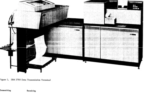
The IBM 2780 Data Transmission Terminal
(Figure 1) enables large volumes of card data to be transmitted at line speed with punched or printed output. The IBM 2780 uses the binary synchronous communications (BSC) procedures over leased, privately owned, or switched networks--in EBCDIC, Six-Bit Transcode, or USASCII. The 2780 can communicate directly (point-to-point) through appropriate interface with another IBM 2780, an IBM System/360 Model 20 through 195*, an IBM System/370 Model 135 through 195, an IBM 1130, an IBM 1800, an IBM System/3, or an IBM 2770. (Figure 2 shows an example of point-to-point operation.) Also, the 2780 may be a station on the same multipoint line facility with other BSC-equipped IBM devices (2770, 1130, 1800, 2715, System/3, and System/360 Model 20). A System/ 360 Model 22 through 195* or a System/370 Model 135 through 195 acts as the control station for a multipoint network. (Figure 3 shows an example of multipoint operation.) The intermix capability of the IBM 2780 and other BSC-equipped IBM terminals and processor terminals is described in the SRL publication, General Information--Binary Synchronous Communications, GA27-3004.
2780 Models
The IBM 2780 is available in four models, permitting a variety of system configurations. The four models are:
• Model 1--Card read and print
• Model 2--Card read, card punch, and print • Model 3--Print only (used as a receive terminal
only)
• Model 4--Card read and card punch
Functional Units of the 2780
The IBM 2780 Data Transmission Terminal consists of:
• A printer similar to the IBM 1443 Printer;
• A card read/punch similar to the IBM 1442 Card Read/Punch;
• A line buffer that stores data received (or data to be transmitted) over a communications line;
*System/360 Model 20 through 195 or 22 through 195, as used in this manual, excludes Model 44 and also Model 67 except in Model 65 mode.
IBM 2780 DATA TRANSMISSION TERMINAL
• An I/O buffer that provides for the intermedi-ate storage of data between the I/O device and the line buffer;
• A Binary Synchronous Adapter, which controls the flow of data over the communications line and maintains synchronization between the transmitting and receiving terminals;
• Card read/punch and printer operator panels; • Control circuitry to control the various
func-tions and units of the terminalo
Terminology
The following terminology is used throughout the remainder of the manual:
• Record. The data in a single card or a single line of print.
• Block. A group of one or more records that are transmitted as a unit (block) and cause a line turnaround to verify the accuracy of the transmission.
• Message. A group of one or more blocks that represent an entity of data.
NOTE: Refer to Glossary.
Communications Facilities
The communications facilities used by the IBM 2780 must have appropriate modulation/demodulation capability. The communications facilities can be either leased common-carrier private lines (chan-nels), common-carrier switched telephone networks, or equivalent privately-owned facilities. When transmission speed is a primary consideration on private-line facilities, it may be advantageous to use
a four-wire (duplex) private line because it can reduce significantly the time required to reverse the direction of transmission for control purposes. Although use of a four-wire (duplex) communi-cations line can minimize turnaround delay, the IBM 2780 cannot receive and transmit data simul-taneously. It is capable of half-duplex data trans-mission only. (Whether or not duplex charges apply depends on the-local common carrier.) Trans-mission speed--1200, 2000, 2400 or 4800 bps (bits per second)--depends on the type of communications facilities u.sed, and must be specified when the IBM 2780 is ordered.
Figure 1. IBM 2780 Data Transmission Terminal
Transmitting Receiving
4
Figure 2. Data Flow, Terminal-to- Terminal Operation
Transmitting Receivins,
IBM 2701 Data Adapter Unit Or IBM 2703 T rans-mission control Unit
IBM System/360
The IBM 2780 connects to communications channels via a data set or modem (modulator/de-modulator) that may be provided by IBM (if available), by the customer, or by a common carrier. The data set must provide an interface to the 2780 that meets the requirements specified by EIA (Electronic Industries Association) RS-232-C for a type D synchronous interface. When non-IBM data sets (modems) are to be used, an IBM representative should be consulted for additional interface infor-mation.
The type of data set, and whether the 2780 is to be used on duplex or half-duplex communications facilities, must be specified when the IBM 2780 is ordered.
Code Structures
The IBM 2780 Data Transmission Terminal can operate with anyone of three code structures. The choice will depend on the application. However, for system compatibility, the same code must be chosen for all terminals on a particular communications line. The three available codes are: Six-Bit Trans-code (Six-Bit Transmission Code); EBCDIC (Exten-ded Binary-Co(Exten-ded-Decimal Interchange Code); and USASCII (United States of America Standard Code for Information Interchange). A composite chart of the three codes, including card codes, is shown in the Appendix to this manual (see Figure 27). Not all the data-link control or end-to-end control char-acters available within each of the three code sets are used by the IBM 2780.
NOTE: The IBM 2780 uses the same data-link and end-to-end control characters in all three codes. The data-link control characters used are: SYN, ENQ, STX, US, ETB, ETX, DLE, NAK, SOH, and EOT. The end-to-end control characters used are: ESC, BEL, HT, and EM. (See" Data-Link and End-to-End Control Characters" section in this manual. )
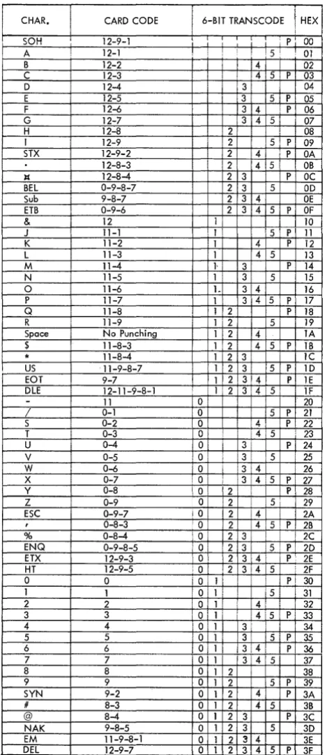
The 64-character Six-Bit Transcode (Figure 4) provides 47 printable graphics (see fTCharacter Sets"), space, 10 data-link control characters, and 6 end-to-end control characters. (The SUB and DEL end-to-end control characters are not used by the 2780). The data-link and end-to-end control char-acters cannot be used as data charchar-acters. The data is transmitted over the communications line low-order first (543210).
NOTE: A 2780 Terminal using the Six-Bit Transcode cannot operate at 4800 bps with an IBM 2703 Transmission Control Unit.
The eight-bit EBCDIC code (Figure 5) provides 256 different characters. These 256 characters com-prise the internal code structure of the IBM System/ 360, and the transmission of System/360 decks is possible when this code is used. The data-link and end-to-end control characters cannot be used as data characters unless the EBCDIC Transparency special feature is installed (see "Special Features" section of this manual). Up to 62 graphics can be printed (see" Character Sets"). Data is transmitted low-order first (76543210) onto the line. When EBCDIC is used, the EOB character performs the data-link control function of ETB. The PRE character per-forms the end-to-end control function of ESC (see "Data-Link and End-to-End Control Characters" section of this manual).
The USASCII code (Figure 6) consists of seven data bits plus a check bit, which by its presence or absence provides each character with odd parity. Sixty-three graphics can be printed with this code
(see "Character Sets"). The data-link and end-to-end control characters cannot be used as data char-acters. The order of bits over the transmission line is low-order to high-order--that is, 1, 2, 3, 4, 5, 6, 7, and check bit.
NOTE: A 2780 terminal cannot transmit or receive USASCII in transparent mode. A 2780 using USASCII cannot communicate with an IBM 2701 Data Adapter Unit's Synchronous Data Adapter Type II (SDA-II) or with an IBM 2703 Transmission Control's terminal control (TC) if: (1) the SDA-II is wired with the Transparency feature, or with the Dual Code feature with USASCII transparency; or (2) the TC is wired with the
Trans-parency feature. (If the 2701 had another SDA-II not so wired, or if the 2703 had another TC not so wired, then the 2780 could communicate with it.)
CARD READ/PUNCH
The card read/punch unit of the 2780 Data Transmis-sion Terminal (see Figure 1) provides the terminal with card input and card output capabilities. The same device is used for the 2780 Models 1, 2, and 4, except that Model 1 has no punching capabilities. The card read/punch unit can read up to 400 cpm (cards per minute), and punch up to 355 cpm. How-ever, the actual throughput speed of the card read/
CHAR. CARD CODE 6-BIT TRANSCODE HEX
I
SOH 12 9 1 - - i i i i i i 1 P 00 I I
A 12-1 ! iSf 01
B 12-2 i 4 I 02
C 12-3 1 I 14 5 ! p, 03
D 12-4 13 04
E 12-5 13 5 i P 05
F 12-6 3 4 . P 06
G 12-7 3 4 51 07
H 12-8 ' 2 i ; 08
I 12-9 i 2 5 P 09
STX 12-9-2 2 4 P OA
12-8-3 ! 2 4 5 OB
It 12-8-4 2 3 P OC
BEL 0-9-8-7 2 3 5 OD
Sub 9-8-7 2 3 4 OE
ETB 0-9-6 2 3 4 5 P OF
& 12 1 10
J I 11-1 11' 5 ! P 11
K 11-2 1 4 P 12
L 11-3 1 4 5 13
M 11-4 1- 3 P 14
N 11-5 1 ! 3 5 15
0 11-6 1- 3 4 16
P 11-7 1· 3 4 5 P 17
Q 11-8 1 2 P 18
R 11-9 i 1 2 5 19
Space No Punching 1 2 4 lA
$ 11-8-3 1 2 4 5, P IB
I * 11-8-4 1 2 3 lC
US 11-9-8-7 1 2 3 5 P 1D
EOT 9-7 1 2 3 4. P lE
DLE 12-11-9-8-1 1 '2 3 ! 4 ! 5 IF
- 11 0 I 20
/ 0-1 0 ! 5 P 21
S 0-2 0 ,4 p. 22
T 0-3 0: i ! :415 23
U 0-4 a 3 P 24
V 0-5 , 0' 3i !5 25
W 0-6 a 3 i 4 26
X 0-7 10 3 415 P 27
Y 0-8 \0 2 P 28
Z 0-9 a 12 ! 5 1 I 29
ESC 0-9-7 iO 2 4 2A
, 0-8-3 a 12 4 5 P 2B
% 0-8-4 OJ 12 31 ! 2C
ENQ 0-9-8-5 10' 12 3 is P 2D
ETX 12-9-3 a 2 314\ P 2E
HT 12-9-5 a: 12 3!4 5, 2F
a I a Oil Pi 30
1 1 a I 1 51 i 31
2 2 ,0 1 41 I 32
3 3 Oil ' 14:5 P 33
4 4 a 1 3 ! 34
5 5 0 1 3 5 P 35
6 6 0 1 13:4: I PI 36
7 7 '0 1 1314 5 37
8 8 0 1 2 i 38
9 9 0 1 2 5 P 39
SYN 9-2 0 1 2 4 P 3A
# 8-3 0 1 2 4 5 3B
@ 8-4 0 1 2 3 P 3C
NAK 9-8-5 0 1 2 3 5 3D
EM 11-9-8-1 a 1 2 3 4 3E
DEL 12-9-7 0 1 2 3 4 5 P 3F
'
Figure 4. Six-Bit Transcode Character Assignment. Also see Composite Code Charts in Appendix.
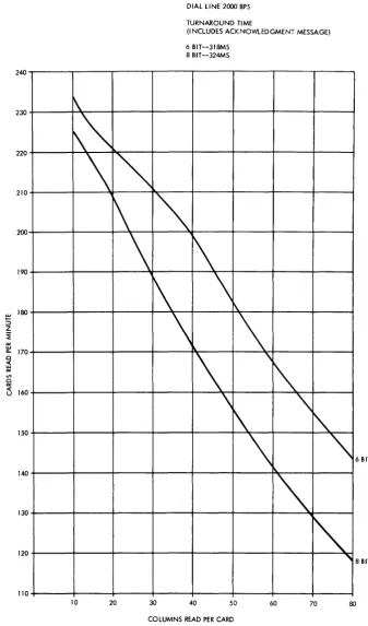
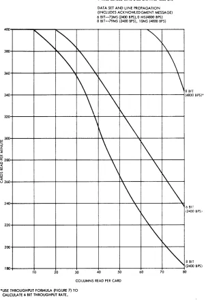
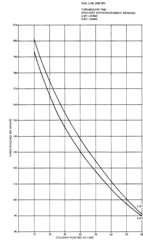
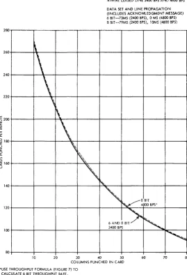
punch depends on the number of card columns that are read or punched, the type of code used (Six-Bit Transcode, EBCDIC, or USASCII), and the type of communications facilities used. (Figure 7 shows the formula for calculating the terminal throughput rate in cards per minute or lines per minute. Figures 8, 9, 10, and 11 show the approximate card read/ punch throughput rates for both dial and leased lines by code.)
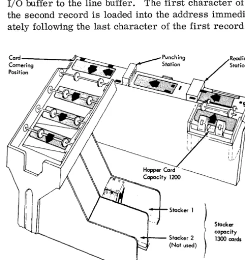
The card read/punch has a hopper with a capacity of about 1200 cards, a card path with read and punch stations, and a single radial stacker with a capacity of 1300 cards. The stacker can be emptied without stopping the unit. Cards feed parallel from the hop-per into the card path, move serially through the read and punch stations to a cornering station, and pass parallel into the stacker transport (Figure 12). Since cards move serially through the read and punch stations, simultaneous reading and punching opera-tions are not feasible.
A card is read by senSing a light through the punched hole in the card. Light from beneath the card is directed to all digit positions of the card col-umns as each column registers above the light source. Any hole punched in the column allows light to pass through and activate a photo transistor. The photo transistor(s) then activate the translation circuitry. Checking circuitry tests the photo transistors twice for each card column and compares the two readings.
If the readings are not alike, an error is indicated.
A card to be punched moves through the read sta-tion and stops with column one registered at the punch station. A geneva (intermittent) drive mechanism moves the card forward, column by column, after each column is punched. A signal generated by each acti ve punch magnet for the column being punched (punch echo check) is compared with the data to be punched, and an error is indicated when a non -compare condition exists.
Basic Operation --Card Read/Punch
[image:10.615.40.273.65.606.2]CHAR. CARD CODE E8CDIC CODE HEX CHAR. CARD CODE E8CDIC CODE HEX
NUL 12-0-1-8-9 00 SPACE NO PUNCHING 1 40
SOH 12-1-9 7 OJ 12-0-1-9 1 7 4]
STX 12-2-9 6 02 12-0-2-9 1 6 42
ETX 12-3-9 6 7 03 12-0-3-9 1 6 7 43
PF 12-4-9 5 04 12-0-4-9 1 5 44
HT 12-5-9 5 7 05 12-0-5-9 1 5 7 45
LC 12-6-9 5 6 06 12-0-6-9 1 5 6 46
DEL 12-7-9 5 6 7 07 12-0-7-9 1 5 6 7 47
12-8-9 4 08 12-0-8-9 1 4 48
12-1-8-9 4 7 09 12-1-8 1 4 7 49
SMM 12-2-8-9 4 6 OA ¢ 12-2-8 1 4 6 4A
VT 12-3-8-9 4 6 7 08 12-3':'8 1 4- 6 7 4B
FF 12-4-8-9 4 5 OC < 12-4-8 1 4 5 4C
CR 12-5-8-9 4 5 7 OD ( 12-5-8 1 4 5 7 4D
SO 12-6-8-9 4 5 6 OE + 12-6-8 1 4 5 6 4E
SI 12-7-8-9 4 5 6 7 OF I 12-7-8 1 4 5 6 7 4F
DLE 12-11-1-8-9 3 10 & 12 1 3 50
DCl 11-1-9 3 7 11 12-11-1-9 1 3 7 51
DC2 11-2-9 3 6 12 12-11-2-9 1 3 6 52
DC3(TM) 11-3-9 3 6 7 13 , 12-11-3-9 1 3 6 7 53
RES 11-4-9 3 5 14 12-11-4-9 1 3 5 54
NL 11-5-9 3 5 7 15 12-11-5-9 1 3 5 7 55
8S 11-6-9 3 5 6 16 12-11-6-9 1 3 5 6 56
IL 11-7-9 3 5 6 7 17 12-11-7-9 1 3 5 6 7 57
CAN 11-8-9 3 4 18 ]2-11-8-9 ] 3 4 58
EM 11-1-8-9 3 4 7 19 11-1-8 1 3 4 7 59
CC 11-2-8-9 3 4 6 1A I 11-2-8 1 3 4 6 5A
11-3-8-9 3 4 6 7 18 $ 1]-3-8 1 3 4 6 7 58
IFS 11-4-8-9 3 4 5 JC * 11-4-8 1 3 4 5 5C
IGS 11-5-8-9 3 4 5 7 ID ) 11-5-8 1 3 4 5 7 5D
IRS 1 ]-6-8-9 3 4 5 6 1E ; 11-6-8 ] 3 4 5 6 5E
IUS 11-7-8-9 3 4 5 6 7 IF ---, 11-7-8 1 3 4 5 6 7 5F
DS ] 1-0-]-8-9 2 20
-
11 1 2 60SOS 0-1-9 2 7 21 / 0-1 I 2 7 61
FS 0-2-9 2 6 22 11-0-2-9 1 2 6 62
0-3-9 2 6 7 23 ] 1-0-3-9 1 2 6 7 63
8YP 0-4-9 2 5 24 11-0-4-9 1 2 5 64
LF 0-5-9 2 5 7 25 11-0-5-9 1 2 5 7 65
ET8(E08) 0-6-9 2 5 6 26 11-0-6-9 1 2 5 6 66
ESC(PRE) 0-7-9 2 5 6 7 27 11-0-7-9 1 2 5 6 7 67
0-8-9 2 4 28 11-0-8-9 1 2 4 68
0-1-8-9 2 4 7 29 0-1-8 1 2 4 7 69
SM 0-2-8-9 2 4 6 2A 12-11 1 2 4 6 6A
0-3-8-9 2 4 6 7 2B , 0-3-8 1 2 4 6 7 68
0-4-8-9 2 4 5 2C % 0-4-8 1 2 4 5 6C
ENQ 0-5-8-9 2 4 5 7 2D - 0-5-8 1 2 4 5 7 6D
ACK 0-6-8-9 2 4 5 6 2E > 0-6-8 1 2 4 5 6 6E
BEL 0-7-8-9 2 4 5 6 7 2F ? 0-7-8 1 2 4 5 6 7 6F
12-11-0-1-8-9 2 3 30 12-11-0 11 2 3 70
]-9 2 3 7 31 12-11-0-1-9 1 2 3 7 71
SYN 2-9 2 3 6 32 12-11-0-2-9 1 2 3 6 72
3-9 2 3 6 7 33 12-11-0-3-9 1 2 3 6 7 73
PN 4-9 2 3 5 34 12-11-0-4-9 1 2 3 5 74
RS 5-9 2 3 5 7 35 12-11-0-5-9 1 2 3 5 7 75
UC 6-9 2 3 5 6 36 12-11-0-6-9 1 2 3 5 6 76
EOT 7-9 2 3 5 6 7 37 12-11-0-7-9 1 2 3 5 6 7 77
8-9 2 3 4 38 12-11-0-8-9 1 2 3 4 78
1-8-9 2 3 4 7 39 1-8 1 2 3 4 7 79
2-8-9 2 3 4 6 3A : 2-8 1 2 3 4 6 7A
3-8-9 2 3 4 6 7 3B I 3-8 1 2 3 4 6 7 78
DC4 4-8-9 2 3 4 5 3C @ 4-8 1 2 3 4 5 7C
NAK 5-8-9 2 3 4 5 7 3D I 5-8 1 2 3 4 5 7 7D
6-8-9 2 3 4 5 6 3E 6-8 1 2 3 4 5 6 7E
SU8 7-8-9 2 3 4 5 6 7 3F
..
7-8 1 2 3 4 5 6 7 7FI
Figure 5. EBCDIC Character Assignment (Part 1 of 2). Also see Composite Code Charts in Appendix.CHAR. CARD CODE CHAR. CARD CODE
12 0 1 8
-
-
-
I I 120-
i! a' 12-0-1 0 !
,
7 81 A 12-1 o 1 i 7 Clb 12-0-2 0 6 82 B 12-2 o 1 6 C2
c 12-0-3 0 6 7 83 C 12-3 o 1 6 7 C3
d 12-0-4 0 5 84 0 12-4 o 1 5 C4
e 12-0-5 0 5 7 85 E 12-5 o 1 5 7 C5
f 12-0-6 0 5 6 86 F 12-6 o 1 5 6 C6
9 12-0-7 0 5 6 7 87 G 12-7 o 1 5 6 7 C7
h 12-0-8 0 4, 88 H 12-8 o 1 4 C8
i 12-0-9 0 4 7 89 I 12-9 o 1 4 7 C9
12-0-2-:8 0 4 6 SA 12-0-2-8-9 o 1 4 6 CA
12-0-3,,:,8 0 4 6 7 88 12-0-3-8-9 o 1 4 6 7 C8
12-0-4-8 0 4 5 8C 12-0-4-8-9 o 1 4 5 CC
12-0-5-8 0 4 5 7 80 12-0-5-8-9 o 1 4 5 7 CD
12-0-6-8 0 4 5 6 8E 12-0-6-8-9 o 1 45 6 CE
12-0-7-8 0 4 5 6 7 8F 12-0-7-8-9 o 1 4 5 6 7 CF
1'-11-1-8 0 3 90 11-0 0 1 3 DO
j 12-11-1 0 3 7 91 J 11-1 o 1 3 7 01
k 12-11-2 0 3 6 92 K 11-2 o 1 3 6 02
I 12-11-3 0 3 6 7 93 L 11-3 o 1 3 6 7 03
m 12-11-4 0 3 5 94 M 11-4 o 1 3 5 04
n 12-11-5 0 3 5 7 95 N 11-5 o 1 3 5 7 05
0 12-11-6 0 3 5 6 96 0 11-6 o 1 3 5 6 D6
P 12-11-7 0 3 5 6 7 97 P 11-7 o 1 3 567 07
q 12-11-8 0 3 4 98 Q 11-8 o 1 3 4 08
r 12-11-9 0 3 4 7 99 R 11-9 o 1 3 4 7 09
12-11-2-8 0 3 4 6 9A 12-11-2-8-9 o 1 3 4 6 OA
12-11-3-8 0 .3 4 6 7 98 12-11-3-8-9 o 1 3 4 6 7 08
12-11-4-8 0 345 9C 12-11-4-8-9 o 1 345 DC
12-11-5-8 0 3 4 5 7 90 12-11-5-8-9 o 1 3,4 5 7 DO
! 12-11-6-8 0 3 4 5 6 9E 12-11-6-8-9 o 1 3 4 5 6 DE
12-11-7-8 0 3 4 5 6 7 9F 12-11-7-8-9 o 1 3 4 5 6 7 OF
11-0-1-8 0 2 AO 0-2-8 012 EO
11-0-1 0 2' 7 AI 11-0-1-9 012 7 El
5 11-0-2 0 2 6 A2 S 0-2 o 1 2 6 E2
t 11-0-3 0 2 6 7 A3 T 0-3 012 6 7 E3
u 11-0-4 0 2 5 A4 U 0-4 012 5 E4
v 11-0-5 0 2 5 7 AS V 0-5 012 5 7 E5
w 11-0-6 0 2, 5 6 A6 W 0-6 012 5 6 E6
x 11-0-7 0 21 5 6 7 A7 X 0-7 012 5 6 7 E7
y 11-0-8 0 21 4 A8 y 0-8 012 4 E8
z 11-0-9 0 21 4 7 A9 Z 0-9 012 4 7 E9
11-0-2-8 0 2: 4 6 AA 11-0-2-8-9 012 4 6 EA
11-0-3-8 0 2 4 6 7 A8 11-0-3-8-9 012 4 6 7 E8
11-0-4-8 0 2i 4 5 AC 11-0-4-8-9 012 4 5 EC
11-0-5-8 0 21 4 5 7 AD 11-0-5-8-9 012 4 5 7 ED
11-0-6-8 0 2 4 5 6 AE 11-0-6-8-9 012 4 5 6 EE
11-0-7-8 0 2 4 5 6 7 AF 11-0-7-8-9 012 4 5 6 7 EF
12-11-0-1-8 0 ,2 3 80 0 0 o 1 2 3 FO
12-11-0-1 0 2 3 7 81 1 1 o 1 2 3 7 Fl
12-11-0-2 0 2 3 6 82 2 2 o 1 2 3 6 F2
12-11-0-3 0 2 3 6 7 83 3 3 o 1 2 3 6 7 F3
12-11-0-4 0 2 3 5 84 4 4 o 1 2 3 5 F4
12-11-0-5 0 2 3 5 ·7 85 5 5 o 1 2 3 5 7 F5
12-11-0-6 0 2 3 5 6 86 6 6 o 1 2 3 5 6 F6
12-11-0-7 0 2 3 567 87 7 7 0 1 2 3 567 F7
12-11-0-8 0 2 3 4 88 8 8 0 1 2 3 4 F8
12-11-0-9 0 2 3 4 7 89 9 9 0 1 2 3 4 7 F9
12-11-0-2-8 0 2 3 4 6 SA 12-11-0-2-8-9 o 1 234 6 FA
12-11-0-3-8 0 2 3 4 6 7 88 12-11-0-3-8-9 o 1 2 3 4 6 7 FB
12-11-0-4-8 0 2 3 14 5 8e 12-11-0-4-8-9 o 1 2 3 4 5 FC
12-11-0-5-8 0 2 3 4 5 7 80 12-11-0-5-8-9 o 1 2 3 4 5 7 FO
12-11-0-6-8 0 2 3 4 5 6 8E 12-11-0-6-8-9 o 1 2 3 456 FE
12-11-0-7-8 0 2 3 4 5 6 7 8F 12-11-0-7-8-9 o 1 2 3 14 5 6 7 FF
CHAR. CARD CODE USASCII CODE HEX CHAR. CARD CODE USASCII CODE HEX
NUL 12-0-9-8-1 00
SOH 12-9-1 1 01
STX 12-9-2 2 02
ETX 12-9-3 1 2 P 03
EOT 9-7 3 04
ENQ 0-9-8-5 1 3 P 05
ACK 0-9-8-6 2 3 P 06
8El 0-9-8-7 1 2 3 07
8S 11-9-6 4 08
HT 12-9-5 1 4 P 09
IF 0-9-5 2 4 P OA
VT 12-9-8-3 1 2 4 08
FF 12-9-8-4 3 4 P OC
CR 12-9-8-5 1 3 4 00
SO 12-9-8-6 2 3 4 OE
SI 12-9-8-7 1 2 3 4 P OF
OLE 12-11-9-8-1 5 10
DCI 11-9-1 1 5 P 11
@ 8-4 7 40
A 12-1 1 7 P 41
8 12-2 2 7 P 42
C 12-3 1 2 7 43
0 12-4 3 7 P 44
E 12-5 1 3 7 45
F 12-6 2 3 7 46
G 12-7 1 2 3 7 P 47
H 12-8 4 7 P 48
I 12-9 1 4 7 49
J 11"; 1 2 4 7 4A
K 11-2 1 2 4 7 P 48
l 11-3 3 4 7 4C
M 11-4 1 3 4 7 P 40
N 11-5 2 3 4 7 P 4E
0 11-6 1 2 3 4 7 4F
P 11-7 7 P 50
Q 11-8 1 7 51
DC2 11-9-2 2 5 P 12
DC3 11-9-3 1 2 5 13
DC4 4-8-9 3 5 P 14
NAK 9-8-5 1 3 5 15
SYN 9-2 2 3 5 16
ET8 0-9-6 1 2 3 5 P 17
CAN 11-9-8 45 P 18
EM 11-9-8-1 1 45 19
SU8 9-8-7 2 45 lA
ESC 0-9-7 1 2 45 P 18
FS 11-9-8-4 3 45 lC
GS 11-9-8-5 1 3 45 P 10
RS 11-9-8-6 2 3 45 P IE
R 11-9 2 7 52
S 0-2 1 2 7 P 53
T 0-3 3 7 54
U 0-4 1 3 7 P 55
V 0-5 2 3 5 7 P56
W 0-6 1 2 3 5 7 57
X 0-7 4 5 7 58·
Y 0-8 1 4 5 7 P 59
Z 0-9 2 4 5 7 P 5A
C 12-8-2 1 2 4 5 7 58
... 0-8-2 3 4 5 7 P 5C
J 11-8-2 1 3 4 5 7 50
--, 11-8-7 2 3 4 5 7 5E
US 11-9-8-7 1 2 3 45 IF
-
0-8-5 1 2 3 4 5 7 P 5FSPACE NO PUNCHES 6 20
I 12-8-7 1 6 P 2]
II
8-7 2 6 P 22
I 8-3 1 2 6 23
"
8-1 6 7 P 60a 12-0-1 1 6 7 61
b 12-0-2 2 6 7 62
c 12-0-3 1 2 6 7 P63
~ 11-8-3 3 6 P 24
% 0-8-4 1 3 6 25
& 12 2 3 6 26
I 8-5 1 2 3 6 P 27
d 12-0-4 3 6 7 64
e 12-0-5 1 3 6 7 P65
f 12-0-6 2 3 6 7 P66
g 12-0-7 1 2 3 6 7 67
( 12-8-5 4 6 P 28 h 12-0-8 4 6 7 68
T 11-8-5 1 4 6 29
* 11-8-4 2 4 6 2A
+ 1~-8-6 1 2 4 6 P 28
0-8-3 3 4 6 2C
-
11 1 3 4 6 P 20i 12-0-9 1 4 6 7 P 69
i 12-11-1 2 4 67 P6A
l( ]2-])-2 1 2 4 67 68
I 12-11-3 3 4 6 7 P 6C
m 12-11-4 1 3 4 67 60
12-8-3 234 6 P 2E
/ 0-1 1 234 6 2F
0 0 5 6 p 30
n 12-11-5 2 3 4 67 6E
0 12-11-6 1 234 67 P 6F
D 12-11-7 567 70
1 1 1 15 6 31 q 12-11-8 1 567 P 71
2 2 12 5 6 32 r 12-11-9 2 567 P 72
3 3 1 2 I!) 6 P 33
4 4 3 5 6 34
5 5 1 3 5 6 P 35
6 6 2 3 I:> 6 P 36
7 7 1 2 3 5 6 37
S- 8 45 6 38
s 11-0-2 1 2 567 73
t 11-0-3 3 567 P 74
u 11-0-4 1 3 567 75
v 11-0-5 2 3 567 76
w 11-0-6 1 2 3 567 P 77
x 11-0-7 4 5 6 7 P 78
9 9 1 45 6 P 39 v 11-0-8 1 4 5 67 79
: 8-2 2 45 6 P 3A
; 11-8-6 1 2 45 6 38
( 12-8-4 3 4 5 6 P 3C
= 8-6 1 3 4 5 6 3D
z 11-0-9 2 4 5 67 7A
Y 12-0 1 2 4 5 67 P 78
I 12-11 3 4 5 6 7 7C
I
T 11-0 1 3 4 5 67 P 70
>
0-8-6 2 3 45 6 3E-
11-0-1 2 3 4 5 6 7 P 7E? 0-8-7 1 2 3 45 6 P 3F DEL 12-9-7 1 2 3 4 5 6 7 7F
I
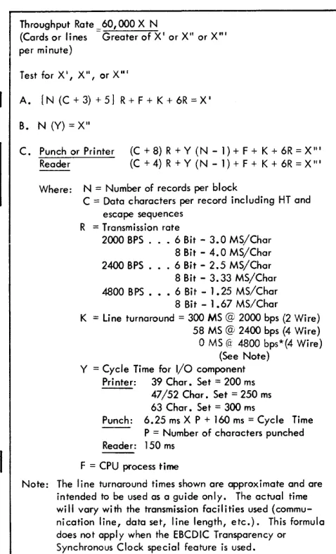
Figure 6. USASCn Character Assignment. Also see Composite Code Charts in Appendix.Throughput Rate 60,000 X N
(Cards or lines Greater of X' or X" or X"' per minute)
Test for X', X", or X"'
A. [N (C + 3) + 5 J R + F + K + 6R = X'
B. N (Y) = X"
C. Punch or Printer (C+8)R+Y(N-1)+F+K+6R=X'"
Reader (C + 4) R + Y (N - 1) + F + K + 6R = X '"
Where: N = Number of records per block
C = Data characters per record including HT and escape sequences
R = Transmission rate
2000 BPS. . 6 Bit - 3.0 MS/Char 8 Bit - 4.0 MS/Char 2400 BPS. . 6 Bit - 2.5 MS/Char 8 Bit - 3.33 MS/Char 4800 BPS ••• 6 Bit - 1.25 MS/Char 8 Bit - 1.67 MS/Char K = line turnaround = 300 MS @ 2000 bps (2 Wire)
58 MS @ 2400 bps (4 Wire)
o
MS (a: 4800 bps*(4 Wire)(See Note) Y = Cycle Time for I/O component
Printer: 39 Char. Set = 200 ms - - 47/52 Char. Set = 250 ms
63 Char. Set = 300 ms
Punch: 6.25 ms X P + 160 ms = Cycle Time P = Number of characters punched Reader: 150 ms
F = CPU process time
Note: The line turnaround times shown are approximate and are intended to be used as a guide only. The actual time will vary with the transmission facilities used (commu-nication line, data set, line length, etc.). This formula does not apply when the EBCDIC Transparency or Synchronous Clock special feature is used.
* Should be verified by modem supplier.
Figure 7. Throughput Formula
are satisfied, cards will be fed until a card is regis-tered at the read or punch station.
Card Reading
A card read/punch ready condition, a result of opera-tion of the start key in transmit mode, causes the Binary Synchronous Adapter to bid for the line. Once the line is secured, I/O buffer controls card reading. Variable-Record Reading (a standard feature of the 2780) increases the throughput rate by allowing the transmission of short card records. When an EM (End-of-Media) character is read from a card, it prevents further reading of that card. This eliminates the transmission of space characters representing the remaining blank columns of the card. The EM char-acter is transmitted and punched, but not printed, at the receiving terminal.
The receipt of a short card record causes the receiving punch to feed another card immediately, which results in increased punch throughput. There-fore, using the EM (end-to-end) control character to indicate the end of a short card record results in both increased transmission efficiency and increased card punch throughput (see discussion of EM in the "Data-Link and End-to-End Control Characters" section of this manual).
An E TX character in a card record provides the same function as EM; however, the E TX results in ending the transmission and deselection of the card read/punch. If neither an EM nor ETX character is part of the card record, 80 columns will be read.
Card reading continues until all cards in the transport
have been read, or until an ETX is read from a card. The last card will be moved automatically to the
stacker and the card read/punch will become not-ready. The following checks are made during a card read operation:
• All characters transferred to buffers are checked for odd parity. Even parity turns Parity Check indicator light on.
• Each column of the card is checked for multiple punches in punching positions 1 through 7. Data Check and Equipment Check indicator lights turn on if multiple punches are detected.
• The US, ETB, NAK, ENQ, Al\.T]) EaT data-link control characters should not be punched in the card. If the US or ETB character is detected, the Data Check indicator lights turn on. If the NAK, ENQ, or EaT character is detected, the Data Check and Equipment Check indicator lights turn on.
Card Punching
A card read/punch ready condition, a result of opera-tion of the start key in rec'eive or punch mode, allows the Binary Synchronous Adapter to respond positively to a line bid by a remote terminal.
[image:14.612.27.266.53.447.2]DIAL LINE 2000 BPS TURNAROUND TIME
(INCLUDES ACKNOWLEDGMENT MESSAGE) 6 BIT--3ISMS
8 BIT --324MS 240
\
~~
\
~
1\
~
\
\
\
\
'-\
\
\
,
~
\
'\
1\
~
\
'\.
BIT230
220
210
200
190
w ISO
I
-::I
Z ~ ~
co.. 170
0
~
"" '" 0
""
« 160 u
150
,
~
140
130
~
~8 BIT
120
110
10 20 30 40 50 60 70 80 COLUMNS READ PER CARD
Figure 8. liM 2780 Card Reader Approximate Throughput Rate--Dial Line (See NOTE in Figure 7)
[image:15.615.76.414.67.641.2]400
~
""~
4-WIRE LEASED LINE 2400 BPS AND 4800 BPS DATA SET AND LINE PROPAGATION (INCLUDES ACKNOWLEDGMENT MESSAGE)
6 BIT--73MS (2400 BPS),O MS(4800 BPS)
8 BIT--79MS (2400 BPS), lOMS (4800 BPS)
~
r\
~
~
\
380
360
1\'
1\
0
\
'\
1\.,
20
\
'\
~
\
34300
\
i\60
\
40
\
20
00
180
'\
1\
\
\
\
\
\
r\.~
8 BIT
( 4800 BPS)'
6 Bit
( 2400 BPSI
8 BIT (2400 BPS) 10 20 30 40 50 60 70 80
COLUMNS READ PER CARD
*USE THROUGHPUT FORMULA (FIGURE 7) TO CALCULA TE 6 BIT THROUGHPUT RATE.
Figure 9. IBM 2780 Card Reader Approximate Throughput Rate--Four-Wire Leased Line (See NOTE in Figure 7)
2780 terminal will attempt to punch the record but will generate parity checks, send an EOT response to the last block checking character, and sound the audible alarm. Punching will be suspended for the remainder of the card (short card record) when the EM (End-of-Media) control character is received. The EM character is punched, the card is released immediately from the punch station, and another card is fed (see discussion on card reading and EM under End-to-End Control Characters in the "Data-Link and End-to-End Control Characters" section of this manual).
Reader and Punch Checking
Reader Checking
When reading cards, the following not-ready condi-tions and reader checks result in transmitting an STX ENQ sequence:
Card read/punch not ready Operation of the stop key Feed clutch --extra feed cycle Equipment check
[image:16.612.33.335.59.498.2]10
00
~
90
\\
Ot
70
\\
\
\\
60
\\
50
\
40
30
20
10
\
\\
\
DIAL LINE 2000 BPS TURNAROUND TIME
(INCLUDES ACKNO'M..EDGMENT MESSAGE) 6 BIT --318MS
8 BIT--324MS
\
~
~
'1'0
'\
~
00'"
~
90
80
8Blf
10 0 30 40 50 60 70 80
COLUMNS PUNCHED IN CARD
Figure 10. IBM 2780 Card Punch Approximate Throughput Rate--Dial Line (See NOTE in Figure 7)
Hopper feed failure
Read-station jam or defective photo transistor Stacker full
Chip box full or not in position
Misfeed or jam at the punch station, or a trans-port jam
Hopper empty after last card is transmitted and End of File key not operated
Punch Checking
When punching, the following not-ready conditions and punch checks are considered as I/O checks and result in an EOT response to a block-check sequence:
Hopper feed failure Read-station jam
Misfeed or jam at punch station
[image:17.613.59.349.65.549.2]4-WIRE LEASED LINE 2400 BPS AND 4800 BPS DATA SET AND LINE PROPAGATION (INCLUDES ACKNOWlEDGMENT MESSAGE) 6 BIT--73MS (2400 BPS), 0 MS (4800 BPS) 8 BlT--79MS (2400 BPS), I OMS (4800 BPS) 280
\
\
I
I
\
\
260
240
220
\
\
"
200
180
1\,
"
~160
,
140
"-
,
\~ ~8BlT
~ 4800 Bps·
6 A N D 8 B I >
~
2400 BPS120
100
~
80
10 20 30 40 50
COLUMNS PUNCHED IN CARD 'USE THROUGHPUT FORMULA (FIGURE 7) TO
CALCULATE 6 BIT THROUGHPUT RATE.
60 70 80
See NOTE in Figure 7 and NOTE under "Multiple-Record Transmission" in the "Special Features" section of this manual.
Figure 11. IBM 2780 Card Punch Approximate Throughput Rate -- Four-vVire Leased Line
Card jam in the transport Feed clutch--extra feed cycle Invalid combination of punches Punch echo check
Card read/punch not-ready Operation of the stop key Hopper empty
Stacker full
Chip box full or not in position
BUFFERS AND CONTROL CIRCUITRY
The control circuitry of the IBM 2780 Data Transmis-sion Terminal is located in the base of the I/O units (card read/punch and printer). The control circuitry contains the electronic circuitry for encoding (genera-ting) data-link control characters and controlling the terminal operation. The control unit also provides two buffers (line and I/O) for the terminal. Using
two buffers enables the read, punch, and print opera-tions to be executed without holding up the communi-cations line.
Line Buffer
The line buffer is a 400-position, 8-bits-per-position buffer with two address registers. The line buffer will store two maximum-length records, the associ-ated end-of-record character (US, ETB, or ETX), and the component-select or carriage-control sequence.
NOTE: Although the line buffer contains 400 storage positions, not all positions are usable unless the Multiple-Record Transmission special feature is installed (see "Special Features").
I/O Buffer
[image:18.615.41.311.62.457.2]store one maximum-length record (transmit or receive) and the associated end-of-record character (only if the punch is selected).
Buffer Operation
Transmit
After the communications path has been established, the first card (record) is read. Reading of the card data continues until an EM, an ETX, or column 80 is loaded into the
I/o
buffer. The record is then transferred to the line buffer. The data transfer terminates after an EM or ETX character, or after 80 characters. Following an EM character, or col-umn 80, a US character is inserted into the line buffer. Recognition of the US or ETX character will advance the input counter.*
Following the US char-acter, the second card is read, data is transferred to the line buffer, and the input counter is advanced to 2. A third card will be read and loaded into the I/O buffer. However, because the input counter is at 2, no transfer will occur. Recognition of an ETX causes reading to be suspended.Data is loaded into consecutive addresses of the line buffer. When the input counter is advanced fol-lowing completion of the transfer, data transmission begins. Recognition of a US or ETX character when transmitting causes the output counter to advance.
If the counters are equal, transmission is suspended until the second data transfer is complete from the I/O buffer to the line buffer. The first character of the second record is loaded into the address immedi-ately following the last character of the first record.
j
l
~'",!7'Y
1300 cardsFigure 12. IBM 2780 Card Feed and Punch Schema tic
When the input counter is advanced to 2, data trans-mission is continuous until a US or ETX character is recognized. The recognition of US or ETX causes the output counter to advance to 2. With the input counter and output counter equal (2), the US char-acter will be changed to ETB unless an end-of-file (EOF) condition exists, in which case the US is changed to ETX. A NAK response to the block-check sequence causes the output counter to be reset,
and a retransmission to occur. The proper DLE response resets both the input and output counters and card reading continues.
Receive
As the first record is received at the receiving ter-minal, the data after the STX character (up to and including the US character) is loaded into the line buffer. If the record is good, the input counter is advanced. The data of the second record is loaded up to and including the ETB or ETX and the input counter advanced if the record is good.
When the input counter is advanced to 1, the record is transferred to the I/O buffer. If the first character is an ESC character, the ESC and the fol-lowing character are removed from data. Upon recognition of the US character, the transfer is termi-nated and the output counter advanced. If the punch is selected, the US (or ETB or ETX) control char-acter is loaded into the I/O buffer. If the printer is selected, space characters will automatically be inserted in the remainder of the buffer. When the I/O operation is complete and the counters are unequal, the second record is transferred to the I/O buffer. The recognition of an ETB or ETX causes the transfer to be completed, the output counter to be advanced, and the space characters to be inserted
if the printer is selected. With the input and output counters at 2, the terminal responds with a DLE
a
or DLE 1 and resets the counters.The input counter is not advanced on an error record. Therefore, the record is not transferred to the
I/o
buffer or outputted to an I/O device. If the first record of a transmission block is in error, the input counter is not advanced, and the following record is ignored. The terminal will respond with NAK. Ifthe first record is received correctly, the input coun-ter is advanced, and the record transferred and out-putted. If the second record is in error, the input
*
The buffer circuitry includes two line-buffer counters (input and output). The input counter is advanced 1 after each record is transferred from the I/O buffer to the line buffer. The output counter is advanced 1 after the complete record is transmitted from the line buffer. Since two records comprise a block, the counters will never advance beyond 2 (normal operation). [image:19.623.68.314.435.696.2]counter is not advanced and the terminal responds with a NAK. The NAK response resets only the input counter. Both records of the retransmission must be received correctly for the second (error record) to be outputted. Receipt of the first recorrl correctly causes the input counter to advance to 1. Since the output counter is also equal to 1, no transfer will occur. With both records received correctly, the input counter will have advanced to 2, a transfer will occur, and normal operation follows.
Buffer Checking
Buffer checking depends on the transmission code: • With the USASCII code, an odd vertical
redun-dancy check (VR C) is performed on all data entering or leaving the buffers.
• With the Six-Bit Transcode, an odd vertical redun-dancy check (VR C) bit is generated for each char-acter that enters the line buffer or the I/O buffer. As data is read from the buffers, it is checked for parity.
• When the EBCDIC code is used, a modified longi-tudinal redundancy check (LR C) is performed. As a record enters a buffer, an odd/even bit count is generated. Following the ETX, ETB, or US char-acter, a character of all 0 (zero) bits is written if
the number of bits in the record is even, or a character of alII bits if the number of bits in the record is odd. As the record is read from the buffers, the odd/even bit count is generated again and compared with the all-O or all-l character. Failure to compare is indicated as a buffer parity check.
In addition to the above checking, the line buffer is checked when transmitting and receiving to determine that the buffer capacity has not been exceeded. Also, a check is made to determine that no more than two records per block are received on a standard machine, or no more than seven records on a machine equipped with the Multiple-Record Transmission special feature. These conditions are indicated as overrun. The I/O buffer is checked to determine that address 170 has not been reached.
If address 170 has been used, it is indicated as an overrun condition.
PRINTER
The 2780 print unit (see Figure 1) provides printed output for the terminal when operating on-line, and enables a card reader-to-printer listing operation to be performed when operating off-line. The print unit is similar in appearance and operation to the
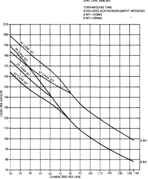
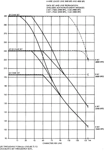
IBM 1443 Printer used in data processing system configurations. The maximum rated speed of the printer is 300 lpm (lines per minute). However, the actual speed depends on the communication facilities used and the number of characters in the character set being used:
39-character set--300 lpm 47/52-character set--240 lpm 63-character set--200 lpm
Figure 7 shows the formula for calculating the termi-nal throughput rate in either lines per minute or cards per minute. Figures 13 and 14 show the approximate printer throughput rate for both dial and leased lines by code.
The basic 2780 terminal has a maximum print speed of 240 lpm and a print cycle of 250 ms. The actual print time required is 198 ms--the remaining 52 ms being used to move the paper forms and restore the print hammers. Skips or line spaces greater than two single spaces take an additional 10 ms per line. Normal forms movement takes place during the last 24 ms of each printing cycle, and two lines can be spaced during this period of time. Each additional line requires another 10 ms. This speed is equivalent to approximately 15 inches per second.
The standard printer can print 80 positions on one line. Both 120 and 144 positions are also available as special features (see "Special Features" section in this publication). All print positions will print all characters of the character set being used. Char-acter density is 10 per inch, thereby providing a printing line of 8, 12, or 14.4 inches.
NOTE: All data to be printed that exceeds the capacity of the printer (80, 120, or 144 print positions) will be lost with no indication unless the record contains more than 170 characters, in which case the terminal will give an overrun error indication.
If the Horizontal Format special feature is used, the 80, 120, or 144 print positions include the print positions involved in the tab functions.
All characters of the character set are mounted on a type bar that travels horizontally on the paper. The type bar ensures that each character of the character set successively passes each print pOSition. To print, a magnet releases a spring-loaded hammer at the proper time so that the desired character is pressed against the ribbon and paper. Characters to be printed are checked for parity while in the buffer. A parity-check error at the receiving terminal results in an EaT (end-of-transmission) character being encoded in place of the normal block-checking response. This may result in a partially-printed line depending upon when the error was detected.
Character Sets
A 63-character set (plus space) is provided with the USASCII code; however, the Selective Character Set special feature is a prerequisite (see "Special Fea-tures"). The standard EBCDIC character set includes 52 printable characters. A 63- or 39-character set is also available as a special feature. The standard Six-Bit Transcode character set includes 47 print-able characters. A 39-character set is also avail-able as a special feature (see Figure 15).
All printable character sets for the print unit include the alphabetic characters A through Z and numeric characters 0 through 9.
TAPE-CONTROLLED CARRIAGE
The IBM 2780's tape-controlled carriage operates similarly to the IBM 1443 Printer tape-controlled carriage. The carriage movement is initiated by a two-character sequence code; however, if no speci-fic spacing instruction is received, the carriage automatically single spaces after printingo
The operator manually sets vertical line spacing for either six or eight lines to the incho This is
ac-DIAL LINE 2000 BPS
TURNAROUND TIME
complished by raising the safety cover and then pushing the tension-lock release lever to the rear
(see Figure 20). The belt can now be shifted from one set of pulleys to the other seto The inner pulley set delivers eight lines per inch; the outer set, six lines per inch. After shifting the belt, press down on the tension lever to restore belt tension. and then latch the safety cover 0
Individual two-character sequence codes for con-trolling the spacing and skipping operations of the carriage permit flexibility of form design. Figure 16 gives the two-character sequence code for each op-eration, by transmission codeo The overflow
opera-tion from form to form (channel 12 to channel 1) after printing is automatic and requires no instruction code.
The paper form is positioned manually, at the beginning of the operation, to receive the first line of print. Thereafter all spacing and skipping is controlled by the two-character spacing and skipping codes received by the terminal. Interlocks prevent printing. while the carriage is· in motion (skipping within the form and overflowing to the next form); therefore, no characters need be inserted in the
(INCLUDES ACKNOWlEDGMENT MESSAGE) 6 BIT --318MS
8 BIT --324MS
210~--~--~--~--~--~--~--~--~--~--~--~--~~
200+---+_--+_--+_--+---+_--+---+---+---+---~--+---~~
190
~~::P
0'.P.PC'--Y--;r-1'~J'~l'
180 . ~1' J:-~~"'-+---+---+---+---+---+---+---+---+---+--~
170~~~:,~
160
~~0~""s~-r....::l...t-"\,---+---+---+---+---+----+----+---~
~l'",'~'
150+---+_~+_~~r-+-~~~+---+---+---+---~--+---~~
5
,,~ ~~
Z140+---~--~--~~~~~_4--_4I~'_4--_4--_4--_+--_+--_+--~
~
,,~\
"'~
~130+---+---+---+---+·-,~~'\~-+---+·~~-4---+---+---+---+--~
~
'\.
"'",,-120+---+_--+_--+_--+_--4-~~--+---4-~~--+---+---+-~
110+1_+--+-_1---+---+--+~~d---+-+-"'-~~~~-+-~
'"
"
1 OO+---+---+---+---+---+---+---+----fI'oooc,,:--+,---+---+--~...,. ... ~6 BIT
~+---+---+---+---+---+---+---+---+---+-~~--~--~~
'
...80 +---+---+---+---+---+---+---+---+---+---+---+-~01.:~:--~8 BIT
I
70+---+---+---+---+---+---+---+---+---+---~--+_--~~
20 30 40 50 60 70 80 90 100 110 120 130 140 144
CHARACTERS PER LINE
Figure 13. IBM 2780 Printer Approxima te Throughput Ra te -- Dial line (See NOTE in Figure 7)
[image:21.613.82.381.350.710.2]4-WIRE LEASED LINE 2400 BPS AND 4800 BPS DATA SET AND LINE PROPAGATION (INCLUDES ACKNO'M..EDGMENT MESSAGE) 6 BIT--73MS (2400 BPS), 0 MS (4800 BPS) 8 BIT--79MS (2400 BPS), 0 MS (4800 BPS) 300 39 CHAR SET
180
"\
'\
--
--i\.
1\
\
\
~
\
~
\
47/52 CHAR SET
-~
"
1\.\
t"
\
\
~
N
63 CHAR SET
)-\
-
-"
~
'\
285
270
255
240
225
210
195
165
150
135
120
105
90
.,'\
,
,
\.
\
~-
---
"-'"
\
1\
'\~
"
\
\
\
\
\
\
\
"
,
.
'
\\
I
----
-,
r\
\
r'1
"
"
'f
8 BIT
(4800 BPS)*
8 BIT
(4800 BPS)*
6 BIT
(2400 BPS)
8 BIT
(2400 BPS)
15 30 45 60 75 90
CHARACTERS PER LINE
lOS 120 135 144
*USE THROUGHPUT FORMULA (FIGURE 7) TO CALCULATE 6 BIT THROUGHPUT RATE.
Figure 14. IBM 2780 Printer Approximate Throughput Rate -- Four-Wire Leased Line (See NOTE in Figure 7)
message to compensate for the time involved in the skipping or overflow operation. (See "ESC (Escape)" under "End-To-End Control Characters" in the "Data":'Link and End-To-End Control Characters" section of this manual.
Carriage-Control Tape
I
The carriage-control tape (see Figure 23) has 12 columnar positions indicated by vertical lines. Thesepositions are called carriage-control channels. Channels 1 through 8 are used when skipping within the form, and channel 12 is used when overflowing from form to form. Channels 9, 10, and 11 are not used.
[image:22.615.39.382.54.550.2]USASCII EBCDIC Six-BIT Transcode
63* 63 52* 39 47* 39
-
-J !
" II
: :
$ $ $ $ $ $
,
,
,
,
,
,1/ 1/ 1/ 1/
<
<
t1 tl* * * *
% % % %
@ @ @ @
( ( (
) ) )
--, --,
I I I
+ + +
; ;
=
[ ¢
]
? ?
& & & &
-
-
-
-/
/
/
/
>
>
\
I
* Standard BarFigure 15. Special Characters Printed in Each Character Set
pin-feed mechanism, which advances the tape syn-chronously with the movement of the printed form through the carriage. Once one of the two-character sequence codes initiates a carriage-skip operation; for example ESC B (see T'End-to- End Control Char-acters" in the "Data-Link and End-to-End Control Character" section of this manual) sensing a hole punched in tape channel 2 will stop the skip operation.
Punching the Tape
A small compact punch (Figure 17) is provided for punching the tape. The following steps should be used to punch the tape:
1. Lay the tape beside the left edge of the form it is to control with the top line (immediately under the glue portion) even with the top edge of the form.
2. Mark the tape in the first channel on the line that corresponds to the first printing line on the form.
3. Make additional marks in the appropriate channels for each of the other skip stops and for the overflow signal required for the form. 4. Repeat steps 1 thru 3 as many times as the
usable length of the tape (22 inches) allows. 5. Mark the line corresponding to the bottom
edge of the last form.
EBCDIC and Carriage Operation USASCII Six-Bit Transcode after Printing
ESC Q ESC / Single Space
ESC R ESC S Double Space
ESC S ESC T Triple Space
ESC A ESC A Skip to Channell
ESC B ESC B Skip to Channel 2
ESC C ESC C Skip to Channel 3
ESC D ESC D Skip to Channel 4
ESC E ESC E Skip to Channel 5
ESC F ESC F Skip to Channel 6
ESC G ESC G Skip to Channel 7
ESC H ESC H Skip to Channel 8
Figure 16. Two-Character Sequence Code for Each Operation
6. For each line marked for punching:
a. Insert the tape in the punch by positioning the line to be punched over the guide line on the base of the punch and placing the center feed holes of the tape over the pins projecting from the base.
b. Position the indicator or dial to the number of the channel to be punched and press on the top of the punch (towards the back).
NOTE: Never punch the tape more than one channel per line.
After the tape is punched, cut and loop it into a belt. Glue the bottom end to the top section (marked "glue") so that the bottom line coincides with the top line. Before the tape is glued, the glaze on the tape should be removed by an ink eraser to ensure a strong bond between the two tape surfaces. The center feed holes should coincide when the two ends of the tape are glued together.
The last hole punched in the tape should be at least four lines from the cut edge because approxi-mately the last half inch of the tape overlaps the glue section when the two ends are spliced. If it is necessary to punch a hole lower than four lines up from the bottom of the form, the tape should be placed with the top line (immediately under the glue portion) four lines lower than the top edge of the form before marking the channels. To compensate for the loss, the tape should then be cut four lines lower than the bottom of the edge of the form.
Inserting the Tape in the Carriage
The follDwing steps should be used to insert a carriage-control tape:
[image:23.613.74.564.76.505.2]1. To gain access to the tape-reading mechanism (Figure 19), press up on the cover release latch and raise the counter-balanced cover of the printer.
2. Turn the manual clutch knob to disengage the clutch.
3. Raise the carriage brushes by lifting the latch located on the side of the carriage brush holder.
4. Place one end of the tape loop (held so that the printed captions can be read) over the pin-feed dri ve wheel so that the pins engage the center drive holes.
5. Place the opposite end of the loop around the adjustable carriage control tape idler. 6. Remove the excess slack from the tape by
loosening the locking knob on the idler and moving the idler in its track. Tighten the knob when the desired tension is reached. The tape should be just tight enough so that it gives slightly when the middle portions of the loop are pressed together. If it fits too tightly, damage can occur to the pin-feed holes.
7. Press the brushes into operating position until they latch and close the printer cover when the tape is in position.
8. Press the Carriage Restore key to bring the tape to its home pOSition and turn the manual clutch knob back to the engaged position. The carriage is now ready to operate.
Paper Forms
The forms used must be designed for use with a tractor feed (Figure 18). Therefore, the forms must be continous with feed holes on both sides. No pro-visio!l is made for pressure feeding of forms. The maximum form width recommended is 16-3/4 inches and the minimum 4 inches.
Carriage Controls and Switches
Clutch Knob
The manual-clutch knob (Figure 18) controls the carriage-tape drive and the form-feeding mechanism. The clutch knob has two settings, OUT and IN. The OUT position disengages the feed clutch so that the form does not move with the carriage drive. The IN position engages the clutch so that the form is moved in synchronization with the carriage tape.
Figure 17. Tape Punch
NOTE: Overprinting will occur if the clutch knob is left in the OUT position.
Typebar Motor Switch
This switch, mounted under the top cover and near the typebar drive, has three positions: ON, OFF, and TYPEBAR REMOVAL (Figure 19). The OFF position turns off the ribbon and typebar motors and de-energizes the solenoid in the typebar drive unit.
The TYPE BAR REMOVAL position turns off the ribbon and typebar motors but leaves the solenoid energized to permit easy operation of the typebar drive handwheel. Use this position when removing or installing a typebar.
CAUTION
A lways remove the typebar before replacing the ribbon. Do not turn this switch to OFF or to TYPEBAR REMOVAL while the typebar is in mo-tion.
Paper Brake
[image:24.617.279.527.57.273.2]Figure 18. Tractor Feed
Figure 19. Printer Right-Hand Controls
Suggested paper-brake settings are: 1-part form, 1-1/2 or 2 drag setting; 2-part form, 1-1/2 or 2 drag setting; 4-part form, 2-1/2 or 3 drag setting; 6-part form, 2-1/2 or 3 drag setting. When forms are inserted into the lower forms guide, fully retract the brake fingers by turning the control as far as possible and locking it.
Typebar Insertion Wheel
This wheel is located on the right side of the car-riage and on the upper rear of the typebar drive unit (see Figure 19). Manually rotating the wheel posi-tions the typebar. Use it when inserting or removing a typebar in the printer. With the power on and the typebar motor switch set to the REMOVAL position
[image:25.613.73.577.59.580.2]to energize the typebar solenoid, the typebar can be removed or replaced. Then turn the typebar inser-tion wheel until the notch on the typebar flag of the 39-, 47-, 52-, or 63-character typebar is aligned proper ly to the decal. Be careful to a void damage to the type bar.
When a typebar has been changed, press the printer reset key before the start key to prevent a Sync-Check indication.
Forms Thickness Adjustment
The platen-positioning knob (see Figure 20) can adjust the platen toward or awa