This Page provides a sequential record of changes for a multi-page drawing. All pages shall carry the same revision letter as shown on this page. Title: FLEX INSTRUCTION SET PROGRAMMING MANUAL
Written
By:
Ubby Bagley Model: C2250A/Part Numbers:
Supersedes: ( 5959-3909. DOC )
Doc. Users: ER:48 DjH: Jwinword 2.0 -
0]
Primary: Secondary:
REVISION HISTORY
Rev Revision Description Date Approved by: MF
A
AS ISSUEDDATE: 11/17/92
DWG. NO:
A-5959-3909-1
10/02/92
PAGE 1 OF 207
FLEX INSTRUCTION SET
Programming Manual
DATE: 11/17/92
DWG. NO:
A-S9S9-3909-1
PAGE 2 OF 207
r I 3
HEWLETTP.O. BOX 39, BOISE, IDAHO 83707, USA
Part No.
A-5959-3909 -1DATE:
11/17/92
DWG. NO: A-5959-3909-1Printed In U.S.A.
PAGE 3 OF 207
... HEWLETT
2.0 INTRODUCTION ... 9
3.0 COMMUNICATION SYSTEM MODEL. ... 10
3.1 TRANSACTION STRUCTURE ... 10
3.2 TRANSACTION MESSAGES ... 11
3.2.1 Command Messages ... 11
3.2.2 Execution Messages ... 11
3.2.3 Reporting Messages ... 11
3.2.4 Transparent Messages ... 12
3.3 DEVICE OPERATION AND TRANSACTION SEQUENCE RELATJONSHIP ... 13
3.4 ,?OWER-ON SEQUENCE ... 14
3.5 DIAGNOSTIC SEQUENCE (SELF TEST) ... 15
3.6 STATUS INFORMATION ... 16
3.7 COMMAND PIPEUNING AND SEEK REORDERING ... 18
3.8 RESOURCE LOCKING ... 19
3.8.1 Event Queuing/Lock Release Notification ... 19
3.8.2 Non responding Host Processing (NRH) ... 19
3.9 OPTIMAL COMMAND SEQUENCE ... 20
3.10 LOGICAL VS PHYSICAL ADDRESSiNG ... 21
3.11 DRIVE STATE DIAGRAM ... 22
3.12 MULTIPLE MECHANISM DEVICES ... 23
4.0 DEVICE COMMANDS ... 24
4.1 LOCATE AND READ ... 24
4.2 LOCATE AND WRITE ... 25
4.3 SET UNIT ... 26
4.4 SET ADDRESS ... 27
4.5 SET LENGTH ... 28
4.6 NO OP ... 29
4.7 SET MECHANISM ... 30
4.8 EXTENDED DESCRIBE ... 31
4.8 EXTENDED DESCRIBE (CONTINUED): ... 32
4.9 INITIAUZE MEDIA ... 52
4.10 SPARE BLOCK ... 54
4.11 LOCATE AND VERIFY ... 56
4.12 INITIATE UTIUTY ... 57
4.13 INITIATE DIAGNOSTIC ... 58
4.14 REQUEST STATUS ... 59
4.15 SET DEVICE LOCK ... 59
4.16 DELETE DEVI·CE LOCK ... 61
4.17 SET UNIT LOCK ... 62
4.18 DELETE UNIT LOCK ... 63
4.19 SET NONRESPONDING HOST (NRH) TIMEOUT ... 64
4.20 SET HOST TO HOST
(HTH)
TIMEOUT ... 654.21 LOCATE AND
ALL ... ; ...
654.22 DIRECTED POST ... 67
4.23 DIRECTED FETCH ... 68
·4.24 DIRECTED BUS 10 ... 69
4.25 DIRECTED UNIT ... 70
4.26 DIRECTED VOLUME ... 71
4.27 DIRECTED ADDRESS ... 72
DATE:
11/17/92
DWG.
NO: A-5959-3909-1 PAGE4
OF207
rr.:tI
HEWLETT5.0 TRANSPARENT COMMANDS ... 75
5.1 REMOTE HOST RESET ... 76
5.2 TRANSPARENT STATUS (TSTAT) ... 77
5.3 CONFIGURE CLEAR ... 78
5.4 LOOPBACK ... 79
5.5 CANCEL ... 80
5.6 IDENTIFY ... 81
5.7 RESET CLEAR ... 82
6.0 HOST STATE DIAGRAMS ... 83
7.0 CHANNEL IMPLEMENTATION ... 86
7.1 INTRODUCTION ... 86
7.2 HPFL OVERVIEW ... 87
7.3 FLEX SPECIFIC IMPLEMENTATION ... 90
7.3.1 HPFL Header Format ... 90
7.3.2 Command Message ... 91
7.3.3 Execution Message ...• 92
7.3.4 Report Message ... 93
7.3.5 Asynchronous IMS ... 93
7.3.6 Loopback ... 94
7.3.7 Cancel (Frame Type 6) ... 95
7.3.8 Identify ... 95
7.3.8.1 Universal Virtual Circurt: Identifies ... 96
7.3.8.2 Device Identifies ... 96
7.3.9 Transparent Message ... 97
7.3.10 Remote Unk Reset ... 97
7.3.11 Reset Clear ... 97
7.3.12 Configure Clear ... 98
After this command, the current status is cleared ... 98
7.4 SAMPLE READ SEQUENCE ...
99
7.5 SAMPLE WRITE SEQUENCE ...
100
8.0 HOST TO HOST
COMMUNICATION ...
101
8.1 DIRECT HOST TO HOST COMMUNICATION ...
102
8.2 BROADCAST HOST TO HOST COMMUNICATION ...
103
8.3 WHO'S WHO IN HOST TO HOST
COMMUNICATION ... 105
8.4 MESSAGE ... 106
8.5 REPORT ... 107
9.0
UTIUTIES ...108
9.1
READ DRIVE TABLES UTlUTY ...111
9.2 READ RUN-TIME LOG UTIUTY ... 114
9.3 READ ERT LOG UTIUTY ... 117
9.4 READ FAULT LOG UTlUTY ... 120
9.5
ClEAR
LOGSUTlUTY ...
1259.6 ERROR RATE TESTS ... 126
9. 7 BUTTERFLY SEEK UTIUTY ... 129
9.8
PRESET DRIVE UTIUTY ... 1309.9 READ REVISION NUMBERS ... 131
DATE: 11/17/92
DWG. NO:
A-5959-3909-1
PAGE 5
OF207
rI'3 HEWLETT
9.12 REBUILD STATUS UTIUTY ... 135
9.13 FIRMWARE
UPGRADE ...
1369.14 READ FUu.. SECTOR ... 137
APPENDIX A ... 139
FLEX OPCODES ... 139
Appendix B ... 141
HP7937Fl FlEX SPECIFICS ... 141
Appendix
C ...
153HP7936Fl FlEX SPECIFICS ... 153
Appendix D ... 164
C2201A FLEX SPECiFiCS ... 164
Appendix E ... 175
C2204A Flex SPECiFiCS ... 175
Appendix F ... 19()
C225X FlEX SPECIFICS ... 19()
The following sections have been revised since the last distribution. All sections have been updated.
REV: A
DATE: 11/16/92
DWG. NO:
A-5959-3909-1
PAGE 7 OF 207
fi'3
HEWLETTCS/80 INSTRUCTION SET Programming Manual, Hewlett-Packard, JUL 1982
Beevers, Tim, HP7937 Firmware Design Outline, Boise, Idaho, Hewlett-Packard, 1982 Bergquist, EarL HP7937FL Hardware ERS, Boise, Idaho, Hewlett-Packard, 1984 Dolkas, Greg, HPFL Protocol Standard, Roseville, CalIf., Hewlett-Packard Nelson, Marvin, HP7937FL Diagnostics, Boise, Idaho, Hewlett-Packard, 1984 Kazakoff, Jim, HP7937 Derror Descriptions Boise, Idaho, Hewlett-Packard, 1987
Spohn, NorRae, HP7937FL Disc Controller Overview Boise, Idaho, Hewlett-Packard, 1986 Kazakoff, Jim, C220XA Derror Descriptions Boise, Idaho, Hewlett-Packard, 1989
Peterson, Mark, 225X Derror Descriptions Boise, Idaho, Hewlett-Packard, 1992
DATE: 11/16/92
DWG. NO:
A-5959-3909-1
PAGE 8 OF 207r I 3
HEWLETTThis document is a FLEX instruction set programming manual, as it applies specifically to Hewlett-Packard disk drives. Please refer to specific device manuals for more information.
DATE: 11/16/92
DWG. NO:
A-5959-3909-1
PAGE 9 OF 207
~ HEWLETT
3.0 COMMUNICATION SYSTEM MODEL
The descriptions here serve to summarize the function and format of the various messages involved.
In addition, this section introduces device start-up, diagnostic and command pipelining concepts.
3.1 TRANSACTION STRUCTURE
A transaction is a logically complete operation between a system host and the device. A transaction begins with a command received by the device. A report message indicating the transaction passed or failed ends the transaction.
A transaction is split into three possible phases: command, execution, and report. The command and report phases define the transaction. The execution phase transfers data between the host and device only if applicable to the command. Some commands do not transfer data, but they are still executed in the execution phase. If an error occurs during command phase and the data cannot be sent to the host, the device goes to report phase.
DATE: 11/16/92 DWG. NO: A-5959-3909-1 PAGE 10 OF 207
~ HEWLETT
3.2 TRANSACTION MESSAGES
There are three message types which occur in a normal transaction: command messages which contain the device operating commands; execution messages which transfer data between the host and device; and reporting message which contain pass or fail status.
A fourth message type, transparent, is used to compensate for different types of channels and differences
in operating environments.
3.2.1 Command Messages
Command messages are initiated by a host and always go from the host to a device. The contents of the message may vary in length, typically up to 1 Kbytes. A command message is valid only if it occurs during the command phase of a transaction. Command messages contain all device command operation codes (opcodes). See the Device Command section for the specific format of the commands.
3.2.2 Execution Messages
Execution messages contain the data requested by the command. The direction and significance of the message text depends on the command being executed. Possible execution message contents include:
1) Read Data
2) Write Data
3) Utility or Log Information
Execution messages are valid only during the execution phase of a transaction which started with a command which requires an execution message. Some operations (e. g. Spare Block) do not include execution messages.
3.2.3 Reporting Messages
The device initiates reporting messages during the reporting phase of the transaction. All reporting messages consist of at least one byte of status information transmitted from the device to the host. This byte contains the QST AT pass/fail indication. The QST AT byte always reflects the information currently contained in the status report.
A QST AT of zero indicates normal completion. A QSTAT of one indicates an error occurred. The next twelve bytes contain the error information. Please refer to the Status Information Section for error codes.
REV: A
DATE:
11/16/92
DWG. NO:
A-5959-3909-1
PAGE 11 OF 207
Fa
HEWLETT3.2.4 Transparent Messages
Transparent messages compensate for different types of channels and differences in operating
environments. Transparent messages also include interface specific functions or interface testing. Some device specific messages may be required in order to maintain the integrity of the transaction sequence in specific operating environments.
The only transparent message initiated by the device is an Immediate Status Message. (see Channel Implementation Section). This message handles internal device requests, aborted requests, and power recovery. An IMS contains status information which is described in the Status Information paragraph. These messages occur during the report phase.
The transparent messages initiated by the host are described in the Transparent Commands Section.
DATE: 11/16/92
DWG. NO:
A-5959-3909-1
PAGE 12 OF 207
3.3 DEVICE OPERATION AND TRANSACTION SEQUENCE RELATIONSHIP
In its idle state, the device is in the command-ready state. When a command message is received, it is buffered, parsed, and validated. If the command and its parameters are valid, the device enters the execution state and begins to carry out the command. If not, the device enters the report phase.
In the execution state, the operation requested by the host is performed. If a data transfer is involved, the drive will request an execution message from the host. The execution message is not used for transactions which do not involve a transfer of information. When the requested operation is complete, the device computes the status of the operation and then enters the reporting state.
DATE: 11/16/92 DWG. NO: A-5959-3909-1 PAGE 13 OF 207
3.4 POWER-ON SEQUENCE
The device executes the following power on sequence:
1) execute internal diagnostics
2) create status report
3) send IMS indicating power on to all hosts
4) enter an interlock state
When the device enters the interlock state, it will only accept a configure (soft) clear or a reset (hard) clear. Any other commands are aborted with an IMS. This state operates on a individual host basis. The failure of one host to send a clear does not affect the ability of the other hosts to execute commands. If a power on diagnostic failure has occurred, the status information report can be retrieved with a configure (soft) clear. After the soft clear, the diagnostic failure is removed for that host.
The recommended host power on sequence follows.
1) execute an identify on the HPFL subsystem (This command is not executed by the device, so it can be sent before a clear. See Channel Implementation.)
2) send a soft clear to all possible devices on the HPFL
3) execute an extended describe on the devices
DATE:
11/16/92DWG. NO:
A-5959-3909-1
PAGE 14 OF 207
~ HEWLETT
3.5 DIAGNOSTIC SEQUENCE (SELF TESn
The initiate diagnostic command to the controller affects all hosts in the multi-host environment. After the diagnostics complete, the device notifies all hosts of the event. This is necessary as diagnostics are destructive. The following sequence will be executed:
1) The device executes its diagnostics
2) A report message is sent to the issuing host
3) An IMS indicating self test is sent to all non-issuing hosts 4) The device enters an interlock state for non-issuing hosts
The recommended sequence for the non-issuing hosts follows.
1) The host sends a soft clear to the device
2) The host restarts all outstanding commands
DATE:
11/16/92DWG. NO:
A-5959-3909-1
PAGE 15 OF 207
rL~ HEWLETT
3.6 STATUS INFORMATION
The device returns status information by two methods. A status message may be returned in the report message or a level 3 IMS(lmmediate Status) message may be returned. The device uses the report message to indicate a problem occurred in the transaction, but the transaction was able to follow a normal sequence. The IMS message is used to indicate a problem that caused the transaction to abort. Both messages use the same basic format and any common errors have the same values.
Il\tIS Message Format
~ byte 1 byte 2
0= cancel
(used only by the host) 1 = command error
2 = message length 3 = Reset
4 = Resource Information
5 = Hardware Error
6
=
Link Protocol7 = Port Events 8 = Access Error
9
=
Information Error1 = illegal opcode 2 = module addressing 3 = address bounds 4 = parameter bounds 5 = illegal parameter 6 = message sequence
1 = power on 2 = initiate sequence
1 = device available 2 = non-responding host 3 = resource unavailable 4=virtual circuit in use 6 = unable to skip mechanism 8 = unit available
1 = parity dev to host 2=parity host to dev 3 = diagnostic failure 4=unit fault 5 = controller fault 7 = mechanism fault
2 = pronto protocol error
6
=
toomany
spares7 = upgrade mode 8
=
retransmit6
=
spindle sync fault A=no self testQSTAT QSTAT device ID derror derror mech number
DATE: 11/16/92 DWG. NO: A-5959-3909-1
byte 3
derror derror
PAGE 16 OF 207
~ HEWLETT
Status Messa&e Format
byte 0 byte 1 byte 2 byte 3 5 = Hardware 3 = diagnostic fault
Error 4 = unit fault derror derror 5 = controller fault derror derror 7 = mechanism fault mech number 8 = Access Error
1 =no spares available 2=defective spare
3 = unrecoverable data derror derror overflow
4 = unrecoverable data derror derror 5=end of volume
6=too many spares 7 = upgrade mode 9 = configuration fault
9 = Information 1 = almost out of spares
Error 2 = marginal data derror derror 3 = maintenance track
overflow
4=autosparing invoked 5=XOR parity error
6 = spindle sync fault mech number 7 = skipping mechanism mech number
DATE: 11/16/92 DWG. NO: A-5959-3909-1
byte 4 byte 5
derror derror derror derror
derror derror
derror derror
derror derror
PAGE 17 OF 207
bytes 6-11
target addr target addr target addr
target addr
target addr target addr target addr
target addr
~~ HEWLETT
3.7 COMMAND PIPELINING AND SEEK REORDERING
The device will reorder locate and read commands and locate and write commands. The reordering scheme will be based on seek distance and the length of time a command has waited in the queue. No command or host will be starved. All transactions will be overlapped within the device (pipelining). The overlap will be between command and execution phases and between report and execution. phases. Some transactions will overlap execution phases.
DATE: 11/16/92
DWG. NO:
A-5959-3909-1
PAGE 18 OF 207
~ HEWLETT
3.8 RESOURCE LOCKING
Two levels of resource locking will be provided: device and unit.
When a host installs a device lock, the entire device is inaccessible to other hosts until the device lock is removed. If the other hosts try to access the device when a lock is in effect, that message is rejected with UNA V AILABLE RESOURCE status. See the Set/Delete Device Lock command description.
When a host installs a unit lock, that unit is inaccessible to other hosts until the unit lock is removed. If other hosts try to access the unit when a lock is in effect, the message is rejected with UNA V AILABLE RESOURCE status. See the Set/Delete Unit Lock command description.
3.8.1 Event Queuing/Lock Release Notification
A host who had a transaction rejected because of an unavailable resource is notified when the resource is available. The device accomplishes this through an event queue and lock notification routine. Any time a transaction is rejected due to a lock resource, the event is locked in a lock table. When the lock is removed, the host which had a reject message is notified. This notification is an asynchronous IMS indicating RESOURCE A V AILABLE.
3.8.2 Non responding Host Processing
(NRH)If a host becomes inactive during an execution, report or host to host message, the drive would be forced to wait indefmitely for the host to respond. The device resolves this situation with a NRH processing routine, which allows detection of an inactive host. It is implemented using a programmable timeout, which is set independently by each host (see the Set NRH command). When a NRH timeout occurs, the device issues an IMS to the non responding host and removes the active command. The device then goes into the command ready state and is available to other hosts.
DATE: 11/16/92 DWG. NO: A-5959-3909-1 PAGE 19 OF 207
3.9 OPTIMAL COMMAND SEQUENCE
In
order to minimize controller overhead, an optimal command sequence exists in the device. This sequence is 14 bytes long and consists of set unit, set address, set length and read or write.DATE: 11/16/92
DWG. NO:
A-5959-3909-1
PAGE 20 OF 207fi'3
HEWLETT3.10 LOGICAL VS PHYSICAL ADDRESSING
There are two different ways to view the device. Logical is the term for the way the host sees the device. Physical is the term for the way the controller sees the device. For example, on the HP7937FL, the host sees 1396 cylinders, 13 heads, and 123 sectors/track on the device. Physically to the controller there are
1404 cylinders, 13 heads, and 124 sectors/track. The host also sees sectors move around the track and continue down the cylinder. Physically these sectors are skewed each time the HP7937FL does a head and cylinder switch. These skews, 40 sectors and 59 sectors, compensate for the delay in head and cylinder switches. This means that cylinder 0, head 1, sector
°
lies up vertically with cylinder 0, head 0, sector 40. So when the drive does a head switch after reading cylinder 0, head 0, sector 122, the next sector it is able to read is cylinder 0, head 1, sector 0. No rotational delay is incurred after a head or cylinder switch. This skewing physically shows the sectors spirally down the cylinders. The preceding example contained data specifically for the HP7937FL. The cylinder, head and sector data information for each disk drive will be different.REV: A
DATE: 11/16/92 DWG. NO: A-5959-3909-1 PAGE 21 OF 207Fh"3
HEWLETT
~
--
-
en
-
CDN
0
~
G)
z
0
»
I01
CD
01
CD
•
CAl
CD
0
CD
I
--0
»
G)
m N N
o
'"T1
N
o
...
:!t
~
IJ,)00
I
-tj
::to < C»
en
~
~
crJ
~
se test
report
issuin host
~
---
nonissuing host
3.12 MULTIPLE l\1ECHANISM DEVICES
When multiple mechanisms are configured under one product, the following terminology will be used.
Mechanism:
Unit:
Device:
REV: A
DATE: 11/16/92One physical disk drive; synonymous with "drive"
One logical disk drive group; may consist of one or more mechanisms
One complete peripheral product; may consist of one or more units; may consist of one or more mechanisms
DWG. NO: A-5959-3909-1 PAGE 23 OF 207
4.0 DEVICE COMMANDS
4.1 LOCATEANDREAD
FUNCTION
Locates the data indicated by the target address and transmits it to the host.
COl\1MAND FORMAT
OPCODE (OOH)
DESCRIPTION
The Locate and Read command is validated during the command phase of the transaction, after which the execution phase may begin.
First the device locates the data indicated by the target address. The target address is specified in a Set Address command. Sequential addressing is the default. A failure of any operation up to this point terminates the transaction with an IMS. Once the data is accessible to the host, the device requests an execution message. When an execution message is established, the data transfer begins.
The length of the total data transfer is the number of bytes specified in a Set Length command included in
the message with the Locate and Read command. If Set Length is not specified, the power on or last set length value is used.
If a data error is encountered in the course of the transfer, the device is allowed to attempt correction for an interval specified in the Set Retry Time (Complementary) command. If the data is unrecoverable, the device will determine its most accurate reconstruction of the data and return this to the host. The address of the first sector of any bad data will be included with the report message for that transaction.
The transfer always contains the amount of data requested by the host unless the host intervenes or a hardware fault occurs. If a hardware fault occurs, the device will terminate the message and proceed to the report phase.
PRODUCT SPECIFICS
All products support this command.
REV: A
DATE: 11/16/92 DWG. NO: A-5959-3909-1 PAGE 24 OF 207n'3 HEWLETT
4.2 LOCATE AND WRITE
FUNCTION
Transfers data from the host to a storage area beginning at the address specified by the target address.
COl\1MAND FORMAT
OPCODE (02H)
DESCRIPTION
This command is a means to write data from the host onto the disk media. The opcode is validated during the command phase. The device determines the address and length in the same manner as in the Locate and Read command. If the command is received and decoded correctly, the execution phase commences by locating the area of the media where data is to be written. When device determines it is ready for data, it requests an execution message.
The write may be aborted by hardware problems or host intervention. If the write encountered hardware problems, the data is sunk by the device controller. The device then proceeds to the report phase.
PRODUCT SPECIFICS
All products support this command.
DATE:
11/16/92
DWG. NO: A-5959-3909-1 PAGE 25 OF 207HEWLETI
4.3 SETUNIT
FUNCTION
Used to specify a specific unit number with a mass storage device.
COl\1MAND FORMAT
OPCODE (2XH)
x
= Unit NumberDESCRIYfION
The allowable unit numbers are OH through PH (15). Unit FH always indicates the controller.
PRODUCT SPECIFICS
HP7937FL, HP7936FL:
The device allows only unit OH and unit PH. Unit PH implies the controller.
C2201A, C2204A:
The device allows only unit OH and unit PH. Unit PH implies the controller.
The Set Unit command and the Set Mechanism command are mutually exclusive. Only one of these two commands may exist in the command sequence.
If the Set Unit command is issued, it must be the first command in the command sequence.
If both the Set Unit command and the Set Mechanism command are absent in the command sequence, a Set Unit command will be supplied for the transaction. This supplied Set Unit command will assume the value of the most recently issued Set Unit command.
C225X:
For C225X independent mode, units OH through EH indicate the logical units, while unit FH indicates the controller.
For C225X striped mode, units' OH through 2H indicate the logical units, while unit FH indicates the controller.
For C225X 2
+
2 mode, units OH through 5H indicate the logical units, while unit FH indicates the controller. The Set Unit command and the Set Mechanism command are mutually exclusive. Only one of these two commands may exist in the command sequence.If the Set Unit command is issued, it must be the first command in the command sequence.
If both the Set Unit command and the Set Mechanism command are absent in the command sequence, a Set Unit command will be supplied for the transaction. This supplied Set Unit command will assume the value of the most recently issued Set Unit command.
REV: A
DATE:
11/16/92DWG. NO:
A-5959-3909-1
PAGE 26 OF 207
~ HEWLETT
4.4 SET ADDRESS
FUNCTION
Used to set the value of the target address. Specifies single- or three- vector address mode.
COl\1MAND FORMAT
I
OPCODE (1XH)I
PARAM 1 PARAM2 PARAM3I
PARAM4 PARAM5 PARAM6x
=
0 implies single-vector modeParameters form a single, 6-byte unsigned binary number X = 1 implies three-vector mode
P ARAM 1 - P ARAM 3 = cylinder address P ARAM 4 = head address P ARAM 5 - P ARAM 6
=
sector addressDESCRIPTION
The device uses the set address command to set the value of the device's target address. The target address is then used by other commands accessing data on the device. The device sets the target address to 0 at power on.
Upon completion of a transaction which uses the target address, the target address will point to the sector after the last sector accessed during that transaction, whether or not the transaction was successful. The target address can be obtained from the Request Status execution message.
The Target Address is unlike other Complementary parameters in that it is updated by any command which accesses data, and does not revert to a prior value when another accessing command is sent. This allows sequential data accessing.
In three-vector address mode, the 6-byte address specifi~ in a Set Address command is broken into three fields, each of which contains one vector of the three dimensional address. The vectors are three, one, and two bytes in length, respectively. For disk drives, the 3-byte vector indicates cylinder address, the I-byte vector is the head address, and the 2-byte vector is the sector address.
In single vector (block) address mode, the six byte address field in the Set Address command is treated as one number. The device maps the linear single vector address to an internal cylinder, head, sector address.
If an Address Bounds error occurs during a Set Address command, the target address will be set to zero. The target address is also set to zero any time an End of Volume occurs. The device cheeks for end of volume when a command is decoded.
PRODUCT SPECIFICS
All products support this command.
REV: A
DATE: 11/16/92 DWG. NO: A~5959-3909-1 PAGE 27 OF 2074.5 SET LENGTH
FUNCTION
Defines the number of bytes in a data transfer.
COMMAND FORMAT
I
OPCODE (18H) PARAM I PARAM2 PARAM3PARAM4
Parameters are unsigned binary byte values.
DESCRIPTION
The four bytes following the Set Length opcode contain the byte count of the transfer length. If this field is not included in the command message, the transfer length will be determined by the power on or last set value. A length specification of aliI's (the power on value) implies a transfer size equal to the selected volume. The volume size is determined by the Describe command.
A length specification of all O's will cause drive to locate the data only (seek). No data is transferred. A Real Time command executed in this manner does not require an execution message. After this type of operation, no verification of the target block address is
performed-PRODUCT SPECIFICS
All products support this command.
REV: A
DATE: 11/16/92
DWG. NO:
A-5959-3909-1
PAGE 28 OF 207
4.6 NO OP
FUNCTION
Causes the device to disregard this message byte.
COMMAND FORMAT
I
OPCODE (34H)
DESCRIYI10N
This byte is disregarded if it appears as an opcode in a command message. It may be useful to align messages to word boundaries.
PRODUCT SPECIFICS
All products support this command.
DATE: 11/16/92 DWG. NO: A-5959-3909-1 PAGE 29 OF 207
fi"3
HEWLETT4.7 SET MECHANISM
FUNCTION
Directs a command or utility to a specific mechanism. The appropriate utilities are those requiring specific head data, specific log data or requiring specific mechanism diagnostics.
COMMAND FORMAT
OPCODE (70H)
PARAM 1
PARAM 1
=
Mechanism number, values 0 to 255 (decimal)
DESCRIPTION
This command allows appropriate commands or utilities to be directed to a specific mechanism rather than a logical unit.
The Set Unit command and the Set Mechanism command are mutually exclusive. Only one of these two commands may exist in the command sequence.
If the Set Mechanism command is issued, it must be the first command in the command sequence.
If both the Set Unit command and the Set Mechanism command are absent in the command sequence, a Set Unit command will be supplied for the transaction. This supplied Set Unit command will assume the value of the most recently issued Set Unit command.
All commands, except Set Unit, may accompany this command. No reference state exists for this command, therefore, complementary commands must be present in the command sequence as required by the real time, general purpose or diagnostic utility.
PRODUCT SPECIFICS
HP793TFL, HP7936FL:
This command is not supported.
C2201A, C2204A:
This command is supported as described in the general description. Only mechanism numbers 1 and 2 are allowed.
C22SX:
This command is supported as described in the general description.
Only mechanism numbers OOH through OFH are allowed. Mechanism OFH indicates the controller.
REV: A
DATE: 11/16/92
DWG. NO:
A-5959-3909-1
PAGE 30 OF 207
rlr~ HEWLETT
4.8 EXTENDED DESCRIBE
FUNCTION
Provides the host with information describing the device capabilities.
COMMAND FORMAT
I
OPCODE (OCH)
DESCRIPTION
The contents of the Extended Describe execution message are formatted into a series of two tables. Each table is prefaced with a six byte table descriptor which provides such information as table type and length, record size and number, and header size (see accompanying diagrams). This information is followed by the header and the specified number of fixed length records.
REV: A
Table type 3
Table type 4 or Table type 5
or Table type 6
Table type
(FFH)
MESSAGE LENGlli (2 bytes)
CONTROLLER DESCRIPTION TABLE
UNIT/VOLUME DESCRIPTION
TABLE (ONE FOR EACH UNI1)
(Table type 4)
or
MECHANISM DESCRIPTION
TABLE (ONE FOR MECHANISM SPECIF1ED) (Table type 5)
or
C225X MECHANISM DESCRIPTION
TABLE (ONE FOR EACH MECHANISM) (Table type 6)
TABLE UST TERMINATOR
DATE: 11/16/92 DWG. NO: A-5959-3909-1 PAGE 31 OF 207
rh~ HEWLETT
4.8 EXTENDED DESCRIBE (CONTINUED):
Table type 4 is mutually exclusive with table types 5 or 6. Table type 5 or 6 is only returned when the "Set Mechanism" command accompanies the "Extended Describe" command (and Table type 4 is not returned in this case.) If "Set Mechanism" does not accompany the "Extended Describe" command, then Table type 4 is returned (and Table type 5 is not returned.) Table type 6 is only returned for C225X mech. Table type 5 is returned for all devices other than C225X.
Each table will have the following format:
TS
where,
and,
1
1
1
TS =
TYP= HS
=
RN=
RS =
TYP HS
Table Size Table Type Header Size Number of Records Record Size
TS
=
6+
HS+
(RN*
RS)2
2
2
2
RN RS
HS
RS
RS
RN
[image:32.623.57.556.199.751.2]DATE:
11/16/92DWG. NO:
A-5959-3909-1
Table Descriptor
Header
Record 1
Record 2
RecordRN
PAGE 32 OF 207
~ HEWLETT
Table Type 3 - Controller Description Table
The first table returned in the describe message is the controller description table (type 3). As shown in the table below J this table has all its information contained in the header; there are no data records. The first five bytes of the header contain the same information included in the controller description field (C I -C 5) of the standard Describe execution. Two additional bytes indicate the ID of the port requesting the message (C6) and the number of host ports on the controller (C7).
[image:33.629.54.585.178.774.2]CONTROLLER TABLE
TABLE DESCRIPTOR (values in hex format) FOR HP7937FL, HP7936FL, C2201A. C2204A
hdr Table Size size
#
rec
rec size
I
OOOE
03
08
00
00
type
HEADER (eight single byte fields)
FOR HP7937FL, HP7936FL, C220 I A, C2204A
Cl C2 C3 C4 C5 C6 C7 C8
FOR C225X
hdr #
Table Size type size rec
I
0016
I
03
10
00
(cliC
22J
(v/rc
Ii-
J
FOR C225X
HEADER (sixteen single byte fields)
Cl C2 C3 C4 C5 C6 C7 C8
C9 CIO Cll C12 C13 CI4 CIS C16
DATE: 11/16/92
DWG. NO:
A-5959-3909-1
ree size
00
PAGE 33 OF 207
Fh
3 HEWLETTbyte fields CI-C2 Byte fields C3-C4 byte fields C5 byte fields C6 Description
Installed Unit byte: 1 bit for each unit (Unit 0
=
LSB)Product HP7937FL HP7936FL C2201A C2204A C225X, striped C225X, independent C225X, 2+2
Description Decimal Values 1 1 -3 1-32767 1-63
Maximum instantaneous transfer rate in thousands of bytes per second
Product
HP7937FL HP7936FL C2201A C2204A C225X, striped C225X, independent C225X, 2+2
Description Controller Type
Decimal Values
5000 5000 000 000 000 5000 5000
o
= Integrated single-unit controller 1=
Integrated multi-unit controller 2=
Integrated multi-port controller3 = Integrated multi-port P-Bus only controller 4
=
Integrated multi-unit, multi-port controllerProduct HP7937FL HP7936FL C2201A C2204A C225X, striped
C225X, independent
C225X,2+2
Description Host Port Id (0-7)
Decimal Values 2 2 2,3 2,3 2,4 4 4
DATE:
11/16/92DWG. NO:
A-5959-3909-1
PAGE 34 OF 207
.-£'3
HEWLETTbyte fields C7
byte fields C8
byte fields C9-Cll
Description
Number of host ports provided by controller
Product Decimal Values
HP7937FL 8
HP7936FL 8
C2201A 8
C2204A 8
C225X, striped 8 C225X, independent 8
C225X,2+2 8
Description Controller Mode
o
=
Single integrated controller/unit 1 = Independent2 = Two-plus-two 3 = One with parity 4
=
Two Striped 5 = Two with parity 6=
Four Striped 7 = Four with parity Product Decimal ValuesHP7937FL HP7936FL C2201A C2204A C225X, striped C225X, independent C225X,2+2
Description
o
o
o
o
3,4,5,6, or 7
1 2
Controller Number. Represents actual HP product number XX XX XY (2 digits per byte).
XXXXX = product number, Y
=
option ProductC225X, striped C225X, independent C225X,2+2
Decimal Values
022500 022500 022500
DATE: 11/16/92 DWG. NO: A-5959-3909-1 PAGE 35 OF 207
Fk
3 HEWLETIbyte fields C12-C15
byte fields C16
Description
Controller Specific Information
Product
C225X, striped C225X, independent 225X, 2+2
Description Reserved
Decimal Values
Contents of board settings, Set at power-on Contents of board settings, Set at power-on Contents of board settings, Set at power-on
DATE:
11/16/92
DWG. NO:
A-5959-3909-1
PAGE 36 OF 207
Table Type 4 - Unit and Volume Table
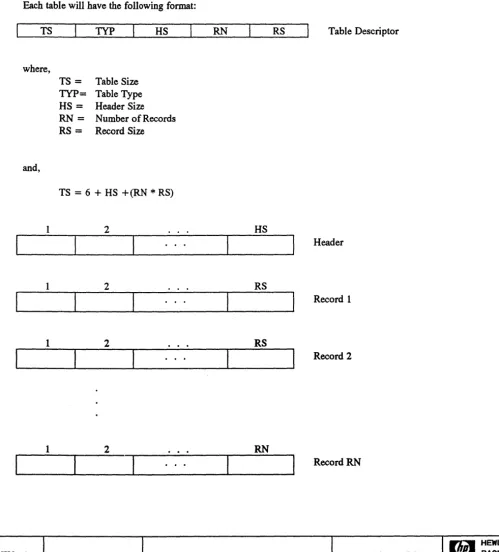
Following the controller table is some number of unit/volume description tables (type 4): One unit/volume table is returned for each unit within the device. The unit description is contained in the header of the table and each record in the table describes a volume within that unit. The HP7937FL contains only one volume. This table includes all of the information in the standard Describe message plus an unit number identifier (UI).
[image:37.623.62.569.166.759.2]UNIT & VOLUME TABLE
TABLE DESCRIPTOR (values in hex format)
Table Size Type
I
0026 04HEADER (eighteen single byte fields)
UI byte fields UI U2 Description Unit Number hdr size 12 # rec 01
Product Decimal Values
byte fields U2 HP7937FL HP7936FL C2201A C2204A C225X, striped C225X, independent C225X, 2+2
Description
General Device Type
o
=
Fixed Disko
o
o
o
0-2 0-14 0-51
=
Removable disk or combination rec sizeOE
UIS
2
=
Tape, fixed block size, or random accessProduct
HP7937FL HP7936FL C2201A C2204A C225X, striped C225X, independent C225X,2+2 Decimal Values
o
o
o
o
o
o
o
DATE: 11/16/92 DWG. NO: A-5959-3909-1 PAGE 37 OF 207
F/£;'1
HEWLETTbyte fields U3-U5
byte fields U6-U7
Description
Device Number. Represents actual HP product number; XX XX XY (2 digits per byte).
XXXXX = product number, Y = option
Product HP7937FL HP7936FL C2201A C2204A C225X, striped C225X, independent C225X, 2+2
Description
Decimal Values
079371 079361 022010 022040 022510 022510 022510
Number of bytes per block
Product
HP7937FL HP7936FL C2201A C2204A C225X, striped C225X, independent C225X, 2+2
Decimal Values
256 256 256 256
512, 1024, or 2048 512
1024
byte fields .:::D=es=c~ri~pt::!.:io=n~ _ _ _ _ _ _ _ _ _ _ _ _ _ _ _ U8 Number of blocks that can be buffered
Product Decimal Values
HP7937FL HP7936FL C2201A C2204A C225X, striped C225X, independent C225X,2+2 128 128 128 128 112 112 112
DATE: 11/16/92
DWG. NO:
A-5959-3909-1
PAGE 38 OF 207
rJ,~ HEWLETT
byte fields U9
byte fields UI0-Ull
byte fields U12-U13
Description
Recommended burst size
(0 burst mode not recommended)
Product Decimal Values
HP7937FL 0
HP7936FL 0
C2201A 0
C2204A 0
C225X, striped 0 C225X, independent 0
C225X, 2+2 0
Description
Block time in microseconds (Time is from beginning of one block to beginning of next.)
Product Decimal Values
HP7937FL 179
HP7936FL 179
C2201A 130
C2204A 130
C225X, striped 210 C225X, independent 210
C225X, 2+2 210
Description
Continues average transfer rate for long (full volume) transfers in thousands of bytes per second
Product
HP7937FL HP7936FL C2201A C2204A C225X, striped C225X, independent C225X, 2+2
Decimal Values
1800 1800 1434 1434
5000
1598 3196
DATE: 11/16/92 DWG. NO: A-5959-3909-1 PAGE 39 OF 207
F4d1
HEWLETTbyte fields U14-U15 byte fields U16-U17 byte fields U18 Description
Optimal retry time in tens of milliseconds
Product
HP7937FL HP7936FL C2201A C2204A C225X, striped C225X, independent C225X, 2+2
Description Decimal Values
80
80
80
80
80
80
80
Access time parameter in tens of milliseconds. (Maximum time from the end of command message text to RTS data or RTR data. Applies to read and write commands only in single host single command environment) Product HP7937FL HP7936FL C2201A C2204A C225X, striped C225X, independent C225X, 2+2
Description Decimal Values
84
84
84
84
84
84
84
Maximum interleave factor
Product
HP7937FL HP7936FL C2201A C2204A C225X, striped C225X, independent C225X,2+2 Decimal Values 1 1 1 1 1 1 1
DATE: 11/16/92
DWG. NO:
A-5959-3909-1
PAGE 40 OF 207
r£"3
HEWLETTRECORD (fourteen single byte fields)
VI
byte fields VI-V3
byte fields V4
V2
Description
Maximum value of cylinder address vector
Product Decimal Values
HP7937FL 1395
HP7936FL 1395
C2201A 1448
C2204A 2897
C225X, striped 1934 C225X, independent 1934
C225X, 2+2 1934
Description
Maximum value of head address vector
Product
HP7937FL HP7936FL C2201A C2204A C225X, striped C225X, independent C225X, 2+2
Decimal Values
12 6
15 15 18 18 18
V14
byte fields ~D:..!:::es~c~ri~p~tio~n~ _ _ _ _ _ _ _ _ _ _ _ _ _ _ _ _ V5-V6 Maximum value of sector address vector
Product Decimal Values
HP7937FL HP7936FL C2201A ·C2204A
C225X, striped C225X, independent C225X,2+2
122 122 112 112 71 71 71
DATE: 11/16/92 DWG. NO: A-5959-3909-1 PAGE 41 OF 207
fi'3 HEWLETT
V7-V12 Maximum value of single-vector address
Product Decimal Values
HP7937FL 2232203
HP7936FL 1116101
C2201A 2619791
C2204A 5239583
C225X, striped 2647079 C225X, independent 2647079
C225X,2+2 2647079
byte fields Descri~tion
V13 Current Interleave factor
Product Decimal Values
HP7937FL 1
HP7936FL 1
C2201A 1
C2204A 1
C225X, striped 1 C225X, independent 1
C225X, 2+2 1
byte fields DescriQtion V14 Volume number
Product Decimal Values
HP7937FL 0
HP7936FL 0
C2201A 0
C2204A 0
C225X, striped 0 C225X, independent 0
C225X, 2+2 0
DATE:
11/16/92DWG. NO:
A-5959-3909-1
PAGE 42 OF 207
fi'3
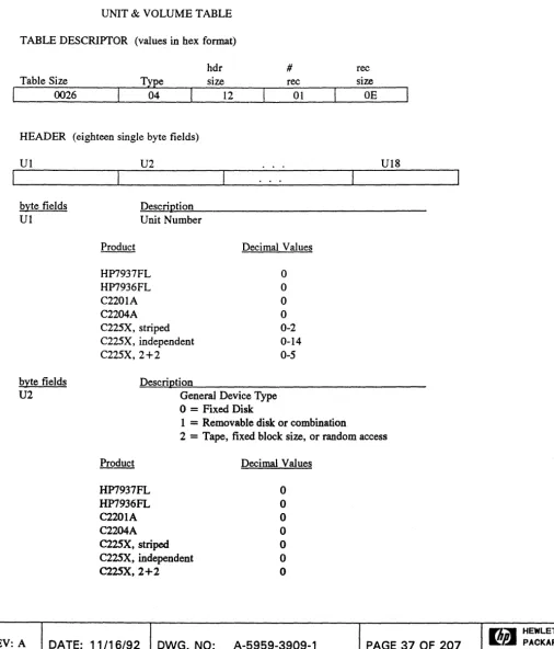
HEWLETTTable Type 5 - Mechanism Table
Following the controller table is some number of mechanism description tables (type 5): One mechanism table is returned for each mechanism within the device. The mechanism description is contained in the header of the table and each record in the table describes a volume of that mechanism.
The HP7936/37 products do not return this table.
The C2201A and C2204A only return the table for the mechanism specified.
[image:43.629.47.563.217.754.2]l\1ECHANISM TABLE
TABLE DESCRIPTOR (values in hex fonnat) FOR C2201A, C2204A
I
00IFTable Size type 05
HEADER (thirteen single byte fields)
Ul U2
Description
hdr size
00
# rec
01
byte fields
Ul Mechanism Number/Address
Product
C2201A C2204A
Decimal Values
1 1-2
DATE: 11/16/92
DWG. NO:
A-5959-3909-1
rec size
OC
U13
PAGE 43 OF 207
n~ HEWLETT
byte fields U2 byte fields U3-U5 byte fields U6-U7 byte fields U8 byte fields
U9
Description Product C2201A C2204A Product C2201A C2204A Product C2201A C2204A Product C2201A C2204A Product C2201A C2204AGeneral Device Type 0= Fixed disk
1 = Removable disk or combination
2=Tape, fixed block size, or random access
Description
Decimal Values
o
o
Device Number. Represents actual HP product number:
XX XX XY
(BCD coded, 2 digits per byte).XXXXX
= product number,Y
= optionY
=
0 for ESDI; Y=
1 for SCSIDescription
Decimal Values
975480
975480
Number of bytes per block
Description
Decimal Values
256 256
Number of blocks which can be buffered
Description Interface Type 0= ESDI Decimal Values 128 128
1 = SCSI
Decimal Values
o
o
. DATE:
11/16/92
DWG. NO:A-5959-3909-1
PAGE 44 OF 207fi"3
HEWLETTbyte fields UI0
byte fields Ull-UI2
byte fields U13
Product
C2201A C2204A
Product
C2201A C2204A
Product
C2201A C2204A
Description
Block time in microseconds (Time is from beginning of one block to beginning of next
Description
Decimal Values
130 130
Continuous average transfer rate for long (full volume) transfers in thousands of bytes per second
Description
Decimal Values
1434 1434
Maximum interleave factor
Decimal Values
RECORD (twelve single byte fields)
VI
byte fields VI-V3
Product
C220IA C2204A
V2
Description
Maximum value of cylinder address vector
Decimal Val ues
1448 1448
VI2
DATE: 11/16/92 DWG. NO: A-5959-3909-1 PAGE 45 OF 207
rltpw.
HEWLETTbyte fields Description
V4 Maximum value of head address vector
Product Decimal Values
C2201A 15
C2204A 15
byte fields Description
V5-V6 Maximum value of sector address vector
Product Decimal Values
C2201A 112
C2204A 112
byte fields Description
V7-V12 Maximum Value of single-vector address
Product Decimal Values
C2201A 2619791
C2204A 2619791
DATE:
11/16/92DWG. NO:
A-5959-3909-1
PAGE 46 OF 207
Fh'3
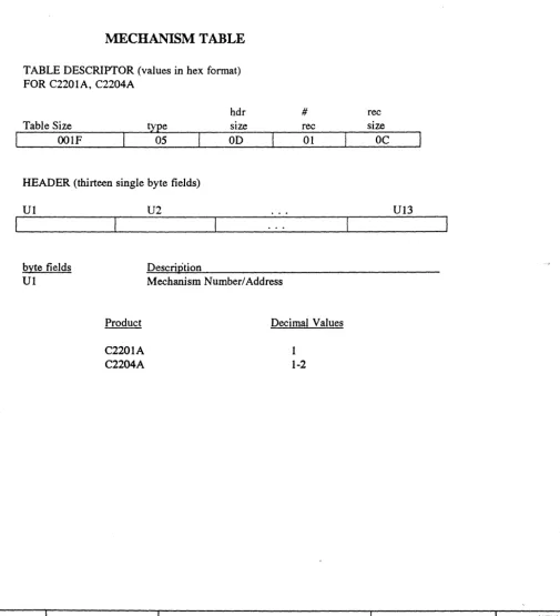
HEWLETTTable Type 6 - Mechanism Table
TABLE DESCRIPTOR (values in hex format) FOR C225X
Table Size type
I
0021 06HEADER (thirteen single byte fields)
VI V2
Description hdr size
OF
# rec 01 byte fieldsUI Mechanism Number/Address
byte fields V2
Product
C225X, striped C225X, Independent C225X, 2+2
Description
General Device Type 0= Fixed disk
Decimal Values
0-14 0-14
0-3,5-8,10-13
1 = Removable disk or combination
2 = Tape, fixed block size, or random access Product
C225X, striped C225X, independent C225X, 2+2
Description Decimal Values
o
o
o
rec sizeOC
VIS byte fieldsV3-V5 Device Number. Represents actual HP product number;
XX XX XY (BCD coded, 2 digits per byte
XXXXX = product number, Y = option
Y =0 for ESDI; Y = 1 for SCSI Product
C225X, striped C22SX, independent C22SX,2+2
Decimal Values
022511 022511 022511
REV: A
DATE: 11/16/92 DWG. NO: A-5959-3909-1 PAGE 47 OF 207byte fields U6-U7
byte fields US
byte fields
U9
Description
Number of bytes per block
Product
C225X, striped C225X, independent C225X, 2+2
Description
Decimal Values
512 512 512
Number of blocks which can be buffered
Product
C225X, striped C225X, independent C225X, 2+2
Description Interface Type
O=ESDI 1 = SCSI Product
C225X, striped C225X, independent C225X, 2+2
Decimal Values
112 112 112
Decimal Values
1
REV: A
DATE: 11/16/92 DWG. NO: A-5959-3909-1 PAGE 48 OF 207~ HEWLETT
byte fields UI0-Ull
byte fields U12-U13
byte fields U14
byte fields UIS
Description
Block time in microseconds (Time is from beginning of one block to beginning of next.)
Product
C22SX, striped
C22SX, independent C225X, 2+2
Description
Decinnal \falues
210
210
210
Continuous average transfer rate for long (full volume) transfers in thousands of bytes per second
Product
C225X, striped C225X, independent C225X, 2+2
Description
Decimal \f alues
5000
1598 3196
Maximum interleave factor
Product
C225X, striped C225X, independent C225X, 2+2
Description Mechanism status O=Good
1 = being rebuilt
2 =non-operational
Decimal \f alues
3 = Unassigned (not broken, but not a member of a logical unit) Product
C225X, striped
C225X, independent C225X, 2+2
Decimal Values
Set at power-on Set at power-on Set at power-on
DATE: 11/16/92
DWG. NO:
A-5959-3909-1
PAGE 49 OF 207
~ HEWLETT
RECORD (twelve single byte fields)
VI
byte fields
VI-V3
byte fields
V4
byte fields V5-V6
byte fields
V7-VI2
V2
Description
Maximum value of cylinder address vector
Product
C225X, striped C225X, independent C225X, 2+2
Description
Decimal Values
1934
1934
1934
Maximum value of head address vector
Product
C225X, striped C225X, independent C225X, 2+2
Description
Decimal Values
18 18 18
Maximum value of sector address vector
Product
C225X, striped C225X, independent C225X, 2+2
Description
Decimal Values
71
71
71
Maximum value of single-vector address
Product
C225X, striped C225X, independent
C225X, 2+2
Decimal Values
2647079
2647079
2647079
DATE: 11/16/92 DWG. NO: A-5959-3909-1
VI2
PAGE 50 OF 207
WA'3
HEWLETTTable Type FFH - Table Terminator
A table type parameter value of FF(hex) indicates the end of the describe data.
[image:51.627.57.554.115.757.2]TABLE TERMINATOR
TABLE DESCRIPTOR (values
in
hex fonnat)
Table Size type
I
0006FF
hdr size
o
#
rec
o
DATE:
11/16/92DWG. NO:
A-5959-3909-1
ree size
00
PAGE 51 OF 207
rL3
HEWLETT4.9 INITIALIZE l\1EDIA
FUNCTION
Instructs the device to overwrite
all
data on the media.
CAUTION
Execution of the Initialize Media command will destroy all user data on the
selected unit.
COM1\1AND FORMAT
OPCODE (37H)
Parameter format:
DESCRIPTION
PARAM 1
PARAM2
PARAM 1 = OOH
Initialize retaining all factory and field spares
PARAM 1 = OlH
Initialize retaining only factory spares
PARAM 1= 02H
Initialize maintenane tracks only
PARAM 1 = ANY OTHER VALUE Invailid command
PARAM 2 = Block interleave byte (unsigned binary number)
The initialize options define which spares will be retained during the initialize operation. No previously defined information in the data fields is retained.
The option to initialize retaining no spares (P ARAM 1 = 3) is provided for factory or CE use only. A "0" interleave factor has the same value as a factor of" 1 ". If a block interleave factor greater than the maximum allowable (as defined by the Describe command) is specified, the interleave value defaults to maximum interleave. No error is generated by this process.
This operation takes several minutes to complete.
REV: A
DATE: 11/16/92
DWG. NO:
A-5959-3909-1
PAGE 52 OF 207
rI3 HEWLETT
PRODUCT SPECIFICS
~937FL,H}q936FL:
This command is implemented as described in the general description.
C2201A, C2204A:
When the unit number is set to OOH then this command operates on the selected unit. This command is not valid for logical unit OFH, the controller.
The command operates on a specific mechanism when the Set Mechanism command is employed.
C225X:
The 02H P ARAM 1 value is not allowed.
When the unit number is set to OOH through OEH then this command operates on the selected unit. This command is not valid for logical unit OFH, the controller.
The command operates on a specific mechanism when the Set Mechanism command is employed.
DATE: 11/16/92
DWG. NO:
A-5959-3909-1
PAGE 53 OF 207
4.10 SPARE BWCK
FUNCTION
Instructs the device to replace a section of media with a spare section of media.
COMMAND FORMAT
OPCODE (06H) PARAM 1
Parameter format: PARAM 1 = OOH
Retain data on reformatted track with
ERT
PARAM 1 = OlH
Retain no data on reformatted track
PARAM 1 = 04H
Retain data on reformatted track without
ERT
DESCRIPfION
Once sparing has been initiated in a given area, it must be completed before processing any new host commands. When the host issues a Spare Block command to the device, it is necessary to reformat the entire data track on which the defective block resides.
If the option to retain no data is specified (PARAM 1
=
1), the sparing operation will be performed but none of the data will be retained. The format pattern is used in place of the data. When the host reads thisformat pattern, no error is returned.
If the option to retain data is specified (PARAM 1 = 0 or 4), then all good data on the track is retained during the sparing operation. Any sector on the track, including the target address, reporting
uncorrectable data will retain its current data. That sector will still report uncorrectable data to the host. If the current uncorrectable data can not be read, then the format pattern will be used, and the sector will report uncorrectable data.
If the option to spare with
ERT
(P ARAM 1 =0) is specified, then an error rate test is ran on the target address. The device then spares the address only if the error rate test discovers an error. If no error is discovered, the address is not spared, and the operation finishes. If the option to spare without ERT (P ARAM 1=
4) is specified, then the device always spares the target address.It is recommended that the host use the option to retain data with
ERT
during normal conditions. A diagram outlining the possible conditions is included in the Host State Diagram section.PRODUCT SPECIFICS
HP7937FL, HP7936FL:
This command is implemented as described in the general description.
C220IA, C2204A:
DATE: 11/16/92
DWG. NO:
A-5959-3909-1
PAGE 54 OF 207
When the unit number is set to OOH then this command operates on the selected unit. This command is not valid for logical unit OFH, the controller.
The command operates on a specific mechanism when the Set Mechanism command is employed.
C22SX:
This command is not valid for the controller.
C22SX independent mode:
This command is implemented as described in the general description.
C22SX striped mode and 2+2 mode:
When a Set Unit OOH through OEH is issued, and an unrecoverable read was previously detected, the Spare Block command will spare the individual mechanism that reported the unrecoverable read.
When a Set Unit OOH through OEH is issued, and no unrecoverable read has been detected, the Spare Block command will spare all the mechanisms in the unit.
When a Set Mechanism OOH through OEH is issued, the individual mechanism is spared.
C225X parity mode:
When a Set Unit OOH through OEH is issued, and an unrecoverable read was previously detected, the Spare Block command will spare the individual mechanism that reported the unrecoverable read.
Following the spare, C225X will recover the data for the individual mechanism that was spared. In order to recover the mechanism data, no skip drive can exist.
When a Set Unit OOH through OEH is issued, and no unrecoverable read his been detected, the Spare Block command will spare all the mechanisms in the unit.
When a Set Mechanism OOH through OEH is issued, the individual mechanism is spared.
DATE:
11/16/92
DWG. NO: A-5959-3909-1 PAGE 55 OF 207HEWLETT
4.11 LOCATE AND VERIFY
FUNCTION
Instructs the device to perform an internal verification of a section of data to ensure that it can be react.
COMMAND FORMAT
OPCODE (04H)
DESCRIPTION
None of this data is transferred to the host so no execution message is required. The Set Length and Set Address (Complementary) commands are used as described earlier.
The verification starts at the target address and continues for the amount of data (in bytes) specified in a Set Length command (or the existing length or power on value). If this byte count length is not an integral multiple of the number of bytes per block the count will be rounded up to verify the entire block.
During verification all correctable data errors are counted and logged into the error log. Verification will terminate immediately with an unrecoverable error. Read retries are not attempted during a Locate and Verify.
PRODUCT SPECIFICS
All products support this command.
DATE: 11/16/92
DWG. NO:
A-5959-3909-1
PAGE 56 OF 207
r I 3
HEWLETT4.12 INITIATE UTILITY
FUNCTION
Directs the device to perform one utility routine.
COMMAND FORMAT
OPCODE (3XH) PARAM 1
PARAM4
PARAM7
Opcode format:
x
= 0: X = 1: X=
2:PARAM2 PARAM3
PARAM5 PARAM6
PARAM8 PARAM9
no execution message
drive will receive execution message drive will send execution message
Parameter format: PARAM 1 = Utility number (drive specific)
DESCRIPTION
P ARAM 2 - P ARAM 9
=
Any parameters required by the utility.The utility number following the Initiate Utility opcode indicates which utility is to be performed. Depending on the utility selected, a predefined (by the drive) number of parameter bytes may be expected to follow the utility number. Please refer to the utilities section for specific details.
PRODUCT SPECmCS
All products support this command.
DATE: 11/16/92 DWG. NO: A-5959-3909-1 PAGE 57 OF 207
rL'3
HEWLETT4.13 INITIATE DIAGNOSTIC
FUNCTION
Directs the device to perform one internally defined diagnostic routine.
COMMAND FORMAT
OPCODE (33H) PARAM 1 PARAM2 PARAM3
Parameter format: P ARAM 1 - P ARAM 2 = Loop parameter P ARAM 3 = Diagnostic section number
DESCRIPTION
This command instructs the device to perform one internally defined diagnostic routine.
Parameter byte PARAM 3 (diagnostic section number) defines which internal diagnostic the drive will perform. (The value of this parameter is device dependent.) Parameter bytes P ARAM 1 and P ARAM 2 (loop control) determine how many times the diagnostic will be performed.
As diagnostics to the controller cause the drive to go off-line, all other hosts will receive an IMS indicating reset - initiate diagnostics.
Currently, the only supported diagnostic is self-test, Diagnostic section number zero (0).
PRODUCT SPECIFICS IUP7937~,IUP7936~
This command must be directed to the device's controller (unit 15).
cnOlA, C2204A:
This command must be directed to the device's controller (unit 15).
C225X:
This command is allowed for all units (0- 14) and for the controller (unit 15).
Diagnostics issued to the controller (unit 15) perform as described. Diagnostics issued to units 0-14 perform mechanism self-tests to each mechanism of the unit.
Diagnostics issued to the controller (unit 15) on the link device is not allowed.
DATE:
11/16/92
DWG. NO:
A-5959-3909-1
. PAGE 58 OF 207
rL'3
HEWLETT4.14 REQUEST STATUS
FUNCTION
Instructs the device to execute the equivalent of a zero length write, and to return (in an execution message) the status report.
CO:MMAND FORMAT
OPCODE (ODH)
DESCRIPTION
The Request Status command executes a zero length write and returns a 12-byte status report (in an execution message) indicating the status of the transaction. This is the same status format as the status returned in the report phase of every command that has a non-zero QSTAT.
Status Message Format
byte 0 byte 1 byte 2 byte 3 5 = Hardware 3 = diagnostic fault
Error 4=unit fault derror derror 5 = controller fault derror derror 7 = mechanism fault mech numb
8 = Access Error 1 = no spares available 2 = defective spare 3 = unrecoverable data
overflow derror derror 4 = unrecoverable
data derror derror 5=end of volume
6=too many spares 7=upgrade mode 9=configuration fault
9 = Information 1 =almost out of spares
2 = marginal data derror derror 3 = maintenance track
overflow
4=autosparing invoked
S=XOR parity error
6 = spindle sync fault mechnumber 7 = skipping mechanism mech number
PRODUCT SPECIFIC
All products
SUpportthis command.
DATE: 11/16/92 DWG. NO: A-5959-3909-1
byte 4 byte 5 bytes 6-11
derror derror derror derror
target addr target addr
derror derror target addr
derror derror target addr
targetaddr derror derror target addr
target addr target addr
PAGE 59 OF 207
~ HEWLETT
4.15 SET DEVICE LOCK
FUNCTION
Locks the entire device for exclusive access by the host issuing the command.
CO:MMAND FORMAT
OPCODE (63H)
DESCRIPTION
This command allows a host to gain exclusive access to the entire device for as long as it wishes. The other hosts are excluded from all access to the device until the lock is removed; any attempt by an excluded host to access the device will fail with an UNA V AILABLE RESOURCE IMS.
PRODUCT SPECIFICS
HP793TFL,HF7936FL:
This command is implemented as described in the general description.
C220IA, C2204A:
This command is implemented as described in the general description.
C225X:
This command is implemented as described in the general description. Additionally, this command is considered an invalid request if any Unit Lock exists.
DATE: 11/16/92 DWG. NO: A-5959-3909-1 PAGE 60 OF 207
~ HEWLETT
4.16 DELETE DEVICE
WCK
FUNCTION
Removes a currently installed device lock.
COMMAND FORMAT
OPCODE (6BH)
DESCRIPTION
This command deletes a device lock, thus freeing the device for access by the other hosts. Any host can unlock the device.
PRODUCT SPECIFICS
IlP7937~, IUP7936~:
This command is implemented as described in the general description.
C2201A, C2204A:
This command is implemented as described in the general description.
C225X:
This command is implemented as described in the general description. Additionally, this command is considered an invalid request if any Unit Lock exists.
DATE: 11/16/92
DWG. NO:
A-5959-3909-1
PAGE 61 OF 207
n 3 '
HEWLETT4.17 SET UNIT LOCK
FUNCTION
Lock a unit for exclusive access by the host issuing the command.
CO:MMAND FORMAT
OPCODE (73H)
DESCRIPTION
This command allows a host to gain exclusive access to an unit for as long as it wishes. The other hosts are excluded. from all access to the unit until the lock is removed; any attempt by an excluded host to access the unit will fall with an UNA V AILABLE RESOURCE IMS.
PRODUCT SPECIFICS
IUP7937~,lUP7936FL:
This command is not supported.
C2201A, C2204A:
This command is not supported.
C225X:
This command is implemented as described in the general description. Additionally, this command is considered an invalid request if any Device Lock exists.
DATE: 11/16/92
DWG. NO:
A-5959-3909-1
PAGE 62 OF 207
rI3 HEWLETT
4.18 DELETE UNIT LOCK
FUNCTION
Remove a currently installed unit lock.
COl\1MAND FORMAT
OPCODE (7BH)
DESCRIPTION
This command deletes a unit lock, thus freeing the unit for access by other hosts. Any host can unlock the unit.
PRODUCT SPECIFICS
IUP7937~, I£P793~:
This command is not supported.
C2201A, C2204A:
This command is not supported.
C225X:
This command is implemented as described in the genera