Vector Analysis and Equivalent Circuit of a
Three-Phase Motor Stator
R.De Four
1, T.Wadi
2Lecturer, Dept. of ECE, The University of the West Indies, St. Augustine, Trinidad, WI 1 PT Lecturer, Dept. of ECE, The University of the West Indies, St. Augustine, Trinidad, WI2
ABSTRACT: Vector analysis is widely used for the analysis, modeling and control of electrical machines. The methodmakes use of vector currents, voltages and magnetic variables but does not represent them in an equivalent circuit of the machine. This paper presents the development of an equivalent circuit for an electromagnetic system consisting of scalar electrical, vector electrical and vector magnetic sections and shows the production of a vector current from its scalar counterpart that leads to the production of vector voltages on the magnetic axis of the system. Resultant current, voltage and magnetic variable vectors associated with a phase winding of a three-phase stator are also developed together with a single vector voltage equation of the system.
KEYWORDS: Vector Analysis, Three-PhaseMotor Stator, Current and Voltage Vector, Equivalent Circuit.
I.INTRODUCTION
Vector analysis is widely used for the analysis, modeling and control of electrical machines. The method makes use of vector currents, voltages and magnetic variables and reflects the physical phenomena occurring in the machines. The application of the vector method to the modeling, analysis and control of electrical machines has many advantages over other methods, some of which are: a reduction in system equations, easier machine control, a clear conceptualization of machine dynamics and easier analytical solution of dynamic transients of machine variables [1]. However, the material presented by Kovacs [2]for the vector analysis of a three-phase stator requires an equivalent circuit to demonstrate the generation of vector currents and the production of vector voltages to clearly formulate the vector method.
This paper presents the development of an equivalent circuit for an electromagnetic system consisting of scalar electrical, vector electrical and vector magnetic sections and shows the production of a vector current from its scalar counterpart that leads to the production of vector voltages on the magnetic axis of the system. A single voltage equation is also developed to represent all three windings of the three-phase stator.
II. RELATED WORK
Vector analysis of electrical machines was developed by Kovacs and Racz[3] and is widely used in the modeling, transient analysis and control of these machines. The vector method has been documented in many books of reputed authors [4 – 7]and has been employed by Holtz [8 – 10] in the development of vector equations for electrical machines. However, the above application of the vector method in the analysis of electrical machines utilised vector currents, voltages and magnetic variables but did not represent them in an equivalent circuit of the machine.
III.EQUIVALENT CIRCUIT OF A PHASE WINDING OF A THREE-PHASE MOTOR STATOR
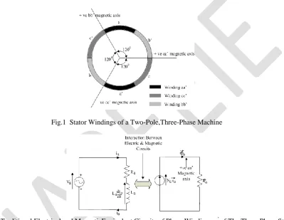
A cross section of the stator windings of a two-pole, three-phase machine is shown in Fig. 1. The phase windings are shown to be displaced from each other by 1200 and the positive direction of current flowing through each winding is upwards through the non-primed side and downwards through the primed side. Using this convention of current flow through the windings, positive magnetic axes were developed for each phase winding, along which all magnetic quantities exists.
where Va represents supply voltage,ia winding current, Ra resistance of winding aa', La self inductance of winding
aa',Rathe reluctance, Na number of turns in winding aa', and fluxϕ aproduced by winding aa'.
However, quantities in the electrical circuit affect quantities in the magnetic circuit and vice versa. As a result of the dependence of both electrical and magnetic variables on each other, the development of an equivalent circuit containing both electrical and magnetic quantities would prove to be very useful in the analysis of electromagnetic systems. Since the three-phase stator is an electromagnetic system, then the development of an equivalent circuit containing both electrical and magnetic quantities would be a powerful tool in the vector analysis approach of this electromagnetic system.
Fig.1 Stator Windings of a Two-Pole,Three-Phase Machine
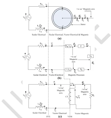
Fig. 2. Traditional Electrical and MagneticEquivalent Circuits of Phase Winding aa’ of The Three-Phase Stator For this analysis, one phase winding of the three-phase stator, winding aa' was initially selected for analysis. This winding is represented in Fig. 3(a) by its center conductors and the currentiathrough the winding is in the positive
direction. Fig. 3(a) is divided into two sections: electrical quantities are presented in the Scalar Electrical section and the other section containing the winding with its electricalscalar currentiaand magnetic variables, magnetic field
intensityH a, flux density B a, flux ϕ a, flux linkage λ a and current vector iaall on the positive (+ ve) magnetic axis of
winding aa'. The electrical scalar current ia, which leaves the Scalar Electrical section of the circuit flows through the
winding and produces vector magnetic field intensityH aalong the positive magnetic axis of winding aa'. This vector magnetic field intensityH amust be produced by a current vector ia on the positive magnetic axis of winding aa', hence,
it can be said that the electrical scalar current iaon passing through winding aa' produces current vector ia on its positive
magnetic axis.
Fig. 3(b) consists of three sections: magnetic processes beginning and ending with current vector ia, a Scalar Electrical
section as described earlier and a Vector Electrical section containing current vector iaseparating the above two
Scalar Electrical section, and the scalar electrical current iaon entering the Vector Electrical section, produces a vector
electric current ia on the magnetic axis of winding aa' as shown in Fig. 3(b). Hence the magnetic axis of winding aa'
completes the circuit making ia and |ia| of equal magnitudes.
Fig. 3. Equivalent Circuit of Three-Phase Stator with Winding aa' Energized(a) Scalar Electrical and Scalar Electrical, Vector Electrical & Magnetic Sections (b) Scalar Electrical, Vector Electrical Sections and Magnetic Processes (c) Scalar Electrical, Vector Electrical and Vector Magnetic Sections [12, 13].
The equivalent circuit of the three-phase stator with phase winding aa' energized is obtained by replacing the Magnetic Processes of Fig. 3(b) with current transformer CT and reluctance Ra. as shown in Fig. 3(c). The turns ratio of current
transformer CT is 1:Na andRais the reluctance to flux ϕ a. The complete equivalent circuit of the three-phase stator with
winding aa' in the Vector Electrical section of the circuit, and the current transformer CT produces the magnetomotiveforce (mmf) Naiain the Vector Magnetic section that drives the fluxϕ athrough the magnetic circuit
reluctanceRa.
The voltage equation in the Scalar Electrical section is given by:
V
a=
i
aR
a+
L
adi
adt
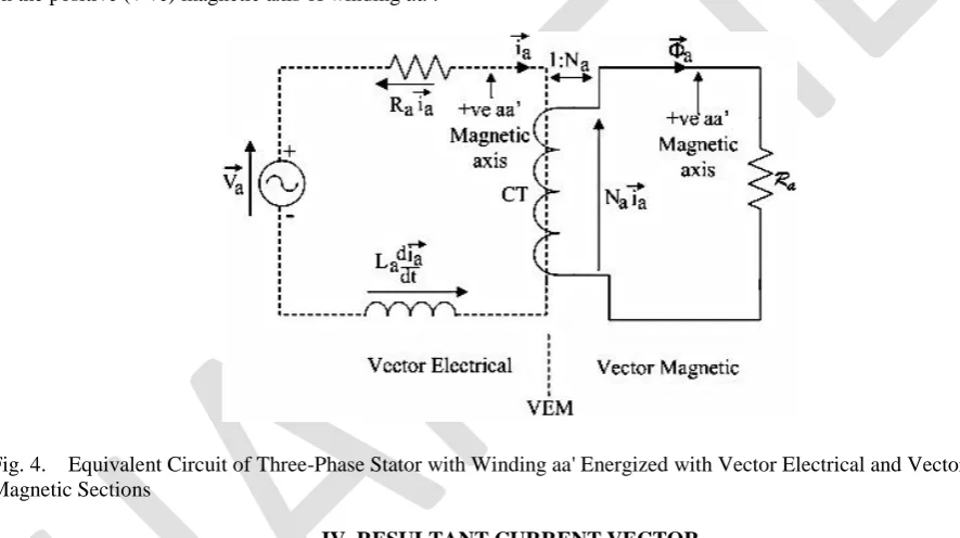
. (1)The voltages in the Scalar Electrical section of Fig. 3 (c) can be referred to the Vector Electrical section of the circuit sinceia =|ia| resulting in:
(2)
and producing the equivalent circuit of Fig. 4, with all voltages residing on the positive (+ ve) magnetic axis of winding
aa'. Therefore the equivalent circuit of the three-phase stator with phase winding aa' energized has been represented by Vector Electrical and Vector Magnetic sections with current vector, voltage vectors and magnetic variables all existing on the positive (+ ve) magnetic axis of winding aa'.
Fig. 4. Equivalent Circuit of Three-Phase Stator with Winding aa' Energized with Vector Electrical and Vector Magnetic Sections
IV. RESULTANT CURRENT VECTOR
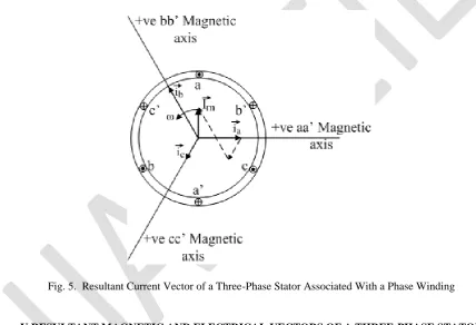
If the phase windings aa', bb', and cc' of Fig. 1 are energized with currents ia, ibandicrespectively, then using the
equivalent circuit developed in Fig. 3(c), current vectors ia, ib and ic would be respectively produced on magnetic axes
aa', bb', and cc' as shown in Fig. 5. These three current vectors ia, ib and ic can be vectorially summed resulting in the
resultant current vector ires[10],
(3)
wherea and a 2are unit vectors representing the position of the positive magnetic axes of windings bb' and cc'
respectively and:
,
.
(4)a
i =I cosm
( )
wt bi =I cosm wt -0
120
(
)
c
i =I cosm wt -0
240
(
)
, (5)then, the resultant current vector is obtained by substituting Eq(5) into Eq(3) [10] and given by:
, (6)
and the resultant current vector associated with phase windings is given by , where:
. (7)
Resolving ipalong each magnetic axis yields the instantaneous values of phase current in Eq(5) [10]. The resultant
current vector associated with phase windings in Eq(7) is of constant magnitudeIm and rotates at a constant angular
velocity of rad/s around the stator.
Fig. 5. Resultant Current Vector of a Three-Phase Stator Associated With a Phase Winding
V.RESULTANT MAGNETIC AND ELECTRICAL VECTORS OF A THREE-PHASE STATOR
The application of the equivalent circuit of Fig. 3(c) to each phase winding of the three-phase, two-pole stator shown in Fig. 1, whose phase windings are displaced from each other by 1200, and energized by three-phase voltages, produces the magnetic and electrical quantities of each phase winding along the phase magnetic axis as shown in Fig. 6.
Each magnetic or electrical phase variable can now be summed vectorially to produce the resultant of that variable [10]. Hence, the resultant magnetic field intensity H res, flux densityB res, flux ϕ res, flux linkage λ res, current vector ires, and
Fig. 6. Magnetic and Electric Quantities of Three-Phase Stator Shown on Magnetic Axes of the Windings [13]
(8) (9) (10)
. (11)
When only phase winding aa' of the three-phase stator is energized, the self inductance Laof that winding is given by:
a
L
=
L
l+
L
m (12)where L1and Lmare the leakage and magnetizing inductances respectively of phase winding aa'. However, when the
. (13) Multiplying the vector voltages on each magnetic axis by 2/3 [10] yields:
2
3
v
a=
2
3
i
aR
a+
2
3
d
l
adt
(14)(15)
. (16)
Summing the voltage on the left of equations (14) to (16) and equating to the sum on the right yields:
. (17) Substituting Equations (7), (11) and (13) in Equation (17) and taking Rs=Ra=Rb=Rcwhere, Rsis the per phase stator
resistance, yields:
. (18)
Equation (18) presents a single voltage equation representing all three windings of the three-phase stator and the voltage equation of any phase winding is obtained by resolving the variables in this equation along the magnetic axis of the winding.
VI. CONCLUSION
The development of an equivalent circuit for a phase winding of a three-phase stator consisting of scalar electrical, vector electrical and vector magnetic sections facilitated the referral of scalar electrical voltages to the vector electrical section of the equivalent circuit due to the equality of scalar and vector current magnitudes. This resulted in voltages and current coexisting with magnetic variables on the magnetic axis of the phase winding, thereby showing that electrical variables can be presented as vector quantities on the magnetic axis of the phase winding. The vector electrical section of the equivalent circuit connected the scalar electrical section to the vector magnetic section, resulting in a single circuit for analysis of the electromagnetic system. The energization of all three windings of the three-phase stator by three-phase voltages produced resultant current, voltage, and magnetic vectors associated with a phase winding and a single vector voltage equation for all three windings. The absence of this single equivalent electrical circuit of the electromagnetic system and the results derived from it has not inhibited growth in the area of transient analysis and modeling of electrical machines, however, its introduction reveals the background of the various phenomena occurring in the machine and shows the development of current and voltage vectors in the electromagnetic system.
REFERENCES
1. Krishnan, R., “Electric Motor Drives: Analysis, Modeling and Control”, Prentice Hall Inc., New Jersey, 2001. 2. Kovács, P. K., “Transient Phenomena in Electrical Machines”,Elsevier Science Publishers, Amsterdam, 1984.
3. Kovács, P. K., and Rácz, I., “Transient Phenomena in Electrical Machines”,Verlag der UngarischenAkademieder Wissenschaften, Budapest, 1959.
4. Vas, P., “Sernsorless Vector and Direct Torque Control”,Oxford University Press, 1998. 5. Boldea, I., and Nasar, S. A.,“Vector Control of AC Drives”, CRC Press, Boca Raton, 1992. 6. Bose, B. K.,“Power Electronics and Variable Speed Drives”,IEEE Press, New Jersey, 1996.
7. Trzynadlowski, A. M., “The Field Orientation Principle in Control of Induction Motors”,Kluwer Academic Publishers, USA, 1994.
8. Holtz, J., “The Representation of AC Machine Dynamics by Complex Signal Flow Graphs”,IEEE Trans. on IndustrialElectronics, Vol. 42, No. 3, pp. 263- 271, June 1995.
9. Holtz, J., “Pulse Width Modulation for Electronic Power Conversion”, Proceedings of IEEE, Vol.82, No.8, pp.1194-1214, Aug. 1994. 10. Holtz, J., “On the Spatial Propagation of Transient Magnetic Fields in AC Machines”,IEEE Transactions on Industry Applications,Vol. 32,
No. 4, pp. 927-937, July/Aug. 1996.
12. De Four, R., “Self Starting Method and Apparatus for Sensorless Commutation of Brushless DC Motors”, U.S. Pat. No. 7,737,651, Issued June 15, 2010.
13. De Four, R., “Vector Analysis, Control and Modeling of Brushless DC Motors”,Ph.D Thesis, Department of Electrical and Computer Engineering, The University of the West Indies, St. Augustine, Trinidad, 2005.
BIOGRAPHY
Ronald De Four received his PhD, MPhil and BSc degrees in Electrical and Computer Engineering from The University of the West Indies, St. Augustine, Trinidad. Presently, he is a Lecturer in the Department of ECE, UWI, Trinidad. His areas of interest include power electronics, variable speed drives and solar power systems.
![Fig. 6. Magnetic and Electric Quantities of Three-Phase Stator Shown on Magnetic Axes of the Windings [13]](https://thumb-us.123doks.com/thumbv2/123dok_us/7792093.1291465/6.595.74.500.128.690/magnetic-electric-quantities-phase-stator-shown-magnetic-windings.webp)
