-
--
--
-
-
-
---
-
-
- -
- -
--
-
- - . .
--.-
--
-
-
----
- -
-~-==
== ';" ==
Maintenance Library
-- -- -- --
-- -- -- --
- . - . .-.-
- -
-
-
---
-
---
-
----
-
--
-
-
-
- -
----
-- -- --
- - -
-
---
-
-
-
Control Unit
Models 51 C, 52C, and 61 C
Maintenance Concepts
Federal Communications Commission (FCC) Statement
Warning: This equipment generates, uses, and can radiate radio frequency energy and if not installed and used in accordance with the instructions manual, may cause interference to radio com-munications. It has been tested and found to comply with the limits for a Class A computing device pursuant to Subpart J of Part 15 of FCC Rules, which are designed to provide reasonable protection against such interference when operated in a commercial environment. Operation of this equipment in a residential area is likely to cause interference in which case the user at his own expense will be required to take whatever measures may be required to correct the interference.
IBM Statement
This warning is also applicable to all attaching units produced for use in the U.S.A. that have been manufactured after December 31, 1980. A notice of compliance has been affixed within the customer access area of all affected units.
Seventh Edition iNovember 19B4i
This major revision obsoletes SY27-2528-5. Significant changes having been made throughout, this edition should be reviewed in its entirety.
The drawings and specifications contained herein shall not be repro-duced in whole or in part without written permission.
IBM has prepared this maintenance manual for the use of IBM
customei engineeis in the installation, maintenance, Oi iepaii of the
specific machines indicated. IBM makes no representations that it is suitable for any other purpose.
Information contained in this manual is subject to change from time to time. Any such change will be reported in subsequent revisions or Technical Newsletters.
References in this publication to IBM products, programs, or services do not imply that IBM intends to make these available in all countries in which IBM operates. Any reference to an IBM program product in this publication is not intended to state or imply that only IBM's program product may be used. Any functionally equiva-lent program may be used instead.
Publications are not stocked at the address given below. Requests for IBM publications should be made to your IBM representative or to the IBM branch office serving your locality.
A form for readers' comments is provided at the back of this publi-cation. If the form has been removed, address comments to IBM Corporation, Department 52Q, Neighborhood Road, Kingston, N. Y. U.S.A. 12401. IBM may use or distribute whatever information you supply in any way it believes appropriate without incurring any obligation to you.
Organization of Manual
Chapter 1. Maintenance Approach and System Overview . . . .
Chapter 2. Subsystem Indicators, Symbols, and Messages . . . .
Chapter 3. Subsystem Error Logs and Test Formats . . . .
Chapter 4. Subsystem Tests, External Tests, and
Subsystem Service Aids . . . .
Chapter 5. Reference Data . . . .
Chapter 6. Tools and Test Equipment . . . .
Appendix A. Support Structure Information Form . . . . . . .
Appendix B. Error Codes . . . .
Appendix C. X.21 Switched Feature . . . .
Appendix D. X.25 Adapter Feature . . . .
List of Abbreviations
Safety Procedures
This section gives the safety practices to be observed by
customer engineers (CEs) and the safety notices that appear
in the manual.
C E Safety Practices
These safety practices include the safety rules for CEs when
they are working on machines, first-aid if an accident
occurs, and reporting of accidents.
Rules for Safety
If (1) you know the safety rules for working with electrical
and mechanical equipment and
(2)
you observe these rules,
you can work safely with IBM equipment.
Do not fear electricity, but respect it.
While you are maintaining IBM equipment:
1.
Observe every safety precaution possible.
2.
Observe the following safety rules.
Work Environment
• Do not work alone under hazardous conditions or near
equipment that has da-ngerous voltages. Always inform
your manager if the conditions or voltages are a possible
problem.
•
Remove all power ac and dc when removing or assembling
major components, when working in the immediate area
of power supplies, when performing mechanical
inspec-tion of power supplies, and when installing changes in
machine circuitry. Pull the power cable plug from the
receptacle to remove the power source.
• Follow special safety instructions, such as handling
cathode-ray tubes and extremely high Voltages, as
out-lined in customer engineering memorandums (CEMs)
and in the Safety Procedures section of the maintenance
manuals.
• Always look for possible hazards in your work
environ-ment. Examp!es of hazards are moist floors,
non-grounded extension cables, power surges, and missing
safety grounds.
• Do not perform any action that makes the product
unsafe or that causes hazards for the customer personnel.
• Before you start the equipment, make sure that other
CEs, and customer personnel, are not in a hazardous
position.
• Do not wear loose clothing that can be caught in the
moving parts of a machine. Make sure that the sleeves of
your clothing are fastened or are rolled above the elbow.
If your hair is long, or if you wear a neck scarf, fasten it
to ma ke it safe.
• Insert your necktie into your clothing or fasten it with a
clip (preferably nonconductive) at approximately 8
centimeters (3 inches) from its end.
• Lift
the equipment or parts by standing or pushing up
with your leg muscles; this action removes the strain
from the muscles in your back. Do not lift any
equip-ment or parts that are too heavy for you.
The maximum load to be lifted is that which, in your
opinion and management's, does not jeopardize your
own health or well-being, or that of other employees.
• Put removed machine covers in a safe place while you
are servicing the machine. Reinstall the covers before
returning the machine to the customer.
• Always keep your CE tool kit away from walk areas so
that other persons cannot trip over it. For example,
keep the kit under a desk or table.
• Observe good housekeeping practices in the area of the
machines while you are performing maintenance and
after completing it.
• After maintenance, reinstall all safety devices, such as
guards, shields, labels, and ground wires. Exchange
safety devices that are worn or defective.
(Remember:
the safety devices protect you from a hazard. You
destroy their purpose if you do not reinstall them
'vvhen
you have completed the service calL)
Electrical Safety
• If possible, always unplug the power-supply cable before
you work on a machine. When you switch off power at
the wall box, lock the switch in the off position or
attach a DO NOT OPERATE tag
(Z229-0237)
to the
switch.
Note:
A non-18M attachment
to
an IBM machine may
be powered from another source and may be controlled
by
a different switch or circuit breaker.
• Switch off all power before (1) removing or assembling
the main units of the equipment, (2) working near to
power supplies, (3) inspecting power supplies, or
(4) installing changes in machine circuits.
• Unless the maintenance documents specifically instruct
you, do not service the following parts with power
on
if the part is removed from its installed position in
the machine: power supplies, pumps, blowers, motor
generators, and other units with voltages that are more
than 30 Vac or 42.4 Vdc. (This rule ensures that correct
grounding is maintained.)
•
If you really need to work on equipment that has
exposed live electrical circuits, observe the following
precautions:
Ensure that another person who is familiar with the
power-off controls is near you. Another person must
be there to switch off the power if necessary.
Do not wear jewelry, chains, metal-frame eyeglasses,
or other personal metal objects.
(Remember:
if the
metal touches the machine, the flow of current
increases because the metal is a conductor.)
Use only insulated probe tips or extenders.
(Remem-ber:
worn or cracked insulation is unsafe.)
Use only one hand while you are working on live
equipment. Keep the other hand in your pocket or
behind your back.
(Remember:
there must be a
complete circuit for an electrical shock to occur.
This precaution prevents your body from completing
the circuit.)
When you use test equipment, set its controls correctly
and use insulated probes that have the correct
electri-cal specification.
Do not touch objects that are grounded, such as metal
fioor strips, machine frames, or other conductors.
Use suitable rubber mats obtained locally, if
necessary.
• When you are working with machines having voltages
more than 30 Vac or 42.4 Vdc, observe the special
safety instructions given in customer engineering
memorandums (CEMs).
•
Never assume that power has been removed from a
cir-cuit. First check to ensure that the circuit has been
powered off.
•
Do not touch I ive electrical circuits with the surface of a
plastic dental mirror.
(Remember:
the surface of the
dental mirror is conductive and can cause damage and
personal injury.)
•
If an electrical accident occurs:
vi
1. Use caution: do not be a victim yourself.
2. Switch off power.
3. Instruct another person to get medical aid.
4.
If
the victim is not breathing, perform
mouth-to-mouth rescue breathing. See "Electrical Accidents"
under "First Aid.
IIMechanical Safety
•
Do not touch moving mechanrcal parts when you
are"Lubricating a part
Checking for play
Doing other similar
vverk.• When using a stroboscope, do not touch ANYTHING
-it may be moving.
Safety Glasses
Wear safety glasses when:
•
Using a hammer to drive pins or similar parts
•
Using a power drill
•
Using a spring hook to attach or remove a spring
• Soldering parts
• Cutting wire or removing steel bands
•
Using solvents, chemicals, or cleaners to clean parts
• Working under any other conditions that could injure
your eyes.
Tools, Test Equipment, and Field-Use Materials
•
Do not use tools and test equipment that have not been
approved by I BM. Make sure that electrical hand tools,
such as Wire-Wrap} tools and power drills, are inspected
regularly.
•
Exchange worn and broken tools anq test equipment.
• Do not use solvents, cleaners, or oils that have not been
approved by IBM.
Summary
Prevention is the main aid to electrical safety. Always
think about electrical safety and use good practice; for
example:
• Make sure that the customer's power receptacle matches
the IBM equipment specifications.
•
Inspect power cables and plugs: check for loose,
damaged, or worn parts.
•
Review the procedure in the maintenance documents
before you remove a part that can hold an electrical
charge from the machine. Carefully discharge the
neces-sary parts exactly as instructed by the procedure.
• Do not use a normal light (for example, a table lamp) as
an extension trouble light at a machine.
Never assume that a machine or a circuit is safe. No
machine is always completely safe. You may not know the
exact condition of a machine, because, for example:
• The power receptacles could be wrongly wired.
• Safety devices or features could be missing or defective.
• The machine could have been damaged in shipment.
• The machine could be deteriorated because it is old or
because it operates in an extreme environment.
• A part could have become defective, thereby causing a
hazard.
• A part could be wrongly assembled.
Also:
• Make sure that the maintenance or changes history is
correct.
• Make sure that all sales changes and engineering changes
are correctly installed.
These are some of the ways that the condition of the
machine could affect safety.
Before you start a service call
or procedure, use good judgment and extreme caution.
First Aid
Serious Injury
1. Summon medical aid.
2. Do not move the victim unless absolutely necessary, to
remove him from ,danger.
3. Try to stop serious bleeding by using pressure points or a
pressure bandage,
4. Loosen the victim's clothing, and keep the victim warm.
Electrical Accidents
When performing rescue procedures for an electrical
acci-dent, do as follows:
• Use caution:
If the victim is still in contact with an
electrical-current source, remove the power; to do this,
you may need to operate the room emergency power-off
(EPO) switch or the disconnecting switch. If you cannot
find the switch, use a dry wooden rod or other
noncon-ductive object to pull or push the victim away from
contact with the electrical-current source.
• Work quickly:
If the victim is unconscious, he or she
may need:
Mouth-to-mouth rescue breathing
External cardiac compression if the heart is not
beating.
INSTRUCT ANOTHER PERSON to call for medical aid
such as an ambulance, rescue service, or a hospital.
Determine whether the victim needs mouth-to-mouth
rescue breathing. If he or she does, perform the following
steps.
CAUTION
Use extreme care when you perform rescue breathing for a
victim who
may
have breathed-in toxic fumes.
Do not
breathe-in air that the victim has breathed out.
1. Prepare for rescue breathing:
a. Ensure that the victim's airway is open and that it is
not obstructed; check the mouth for objects that may
be obstructing the airway, such as chewing gum, food,
dentures, or the tongue.
b. Place the victim on his or her back, put one hand
behind the victim's neck, and put the other hand on
the victim's forehead.
c. Lift the neck with one hand, and tilt the head
back-ward by pressing on the forehead with the other
hand
D .
2. Look, listen, and feel to determine whether the victim is
breathing freely:
a. Put your cheek near to the victim's mouth and nose.
b. Listen and feel for the breathing-out of air. At the
same time, look at the victm's chest and upper
abdomen to see whether they move up and down.
3. If the victim is not breathing correctly:
viii
a. Keep the victim's head tilted backward (see" ).
Continue to press on the forehead with your hand; at
the same time, rotate this same hand so that you can
pinch together the victim's nostrils with your thumb
and finger
II .
fJ
b. Open your mouth wide and take a deep breath. Make
a tight seal with your mouth around the victim's
mouth
II
and blow into the victim's mouth.
II
c. Remove your mouth to let the victim breathe out,
and check that the victim's chest moves down
a
d. Repeat steps band c once every 5 seconds either until
the victim breathes for himself or herself or until
medical aid comes.
Reporting Accidents
Report, to your field manager, all electrical accidents,
pos-sible electrical hazards, and accidents that nearly occurred.
(Remember:
an accident that nearly occurs might be
caused by a design problem; your immediate reporting
ensures that the problem will be solved quickly.)
Report, also, all small electrical shocks.
(Remember:
a
condition that causes a sma!! shock need differ only
slightly
Safety Notices
Personal Safety
The Danger and Caution notices that appear in this manual refer mainly to the 31SD Diskette Drive. Before using this manual, review all the Danger and Caution notices that are listed in the front of the 3274 Control Unit Maintenance Information manual, SY27-2513.
General Personal Safety Information
AC voltages are present on the 31SD drive motor connector and capacitor terminals when the drive motor is running. The motor and the solenoid become hot after continuous use; let the parts cool before attempting servicing. The following Danger and Caution notices appear in this manual:
I
DANGER
Input AC voltage is present in the Prime
Power Box when the 3274 I/O (on/off)
switch is in the
0
(off) position.
I
DANGER
Voltage is still present at the socket when the
power cable is disconnected.
I
DANGER
High voltage may be present at the capacitor
terminals.
CAUTION:
The solenoid case becomes hot after continuous use.
Machine Safety
The notices that appear in this manual refer mainly to the 31SD Diskette Drive. Before using this manual, review all the Warning notices that appear in the 3274
Control Unit Maintenance Information manual, SY27-2513.
General Machine Safety Information
The 31SD Diskette Drive can be damaged if it is not operated or serviced correctly. Do not use I BM cleaning fluid or other chemical cleaning fluids near plastic parts. Never use damaged diskettes in a 31SD Diskette Drive. Diskettes that are damaged physically (creased or bent) or contaminated by pencil marks, finger marks, or cleaning fluids can cause data errors, equipment errors, or head damage. The following Warning notices appear in this manual:
Warning: Do not attempt to remove the collet/
flat spring before removing the bail. Too much
pressure or binding can damage the spring.
Warning: Damage to the head can occur if the
pressure pad is permitted to hit the head.
Warning: Too much pressure or binding of the
flat spring will damage the spring.
Warning: The head/carriage assembly is adjusted
and tested at the factory. Do not attempt to
adjust or repair any part of this assembly.
Warning: The head area can be easily damaged
or contaminated. Read the following before
exchanging a pressure pad:
• Ensure that your tools are clean; use isopropyl
alcohol (part 2200200) and a clean tissue
(part 2162567), or use an alcohol pad (part
9900679).
• Do not touch the pressure pad with your
fingers.
• Be careful not to damage the new pressure
pad or loosen any of the pad's surface. The
layer of adhesive on the new pad is very thin;
do not damage the adhesive. Do not let the
adhesive touch the surface of the pad that
will touch the diskette. Do not use
damaged pads.
• Do not scratch the head load arm.
• Do not let the head load arm hit the read/
write head.
• Move the head load arm as little as possible.
The tension spring can come out.
Warning; The head/carriage service check must be
performed with the diskette drive installed (or
with the diskette drive in the same position as
when installed), or the adjustment might not be
accurate.
Warning: The head/carriage assembly adjustment
must be performed with the diskette drive
installed (or in the same position as when
installed), or the adjustment might not be
accurate.
Warning: The band must not be bent or
damaged in any way.
Warning: When you i-nstall the head/carriage
assembly, ensure that the bail is under the head
load arm. Ensure that the bail return spring is
correctly installed. Ensure that the band is
not damaged in any way.
Warning: The band is easily damaged. Do not
bend, crease, or scratch the band. Do NOT use
a damaged band.
Preface
This manual contains the information needed by the
sup-port field engineering (FE) Cllstomer engineer to maintain
the IBM 3274 Control Unit Models 51 C, 52C, and 61 C.
The maintenance procedures described in this manual
and performed by the support FE customer engineer repre·
sent a part of the overall support structure for the 3274
Control Unit. This support structure begins at the 3274
operator level and is briefly described as follows:
• 3274 Operator -
Performs initial problem isolation and
recording of 3274 status indications by following the
procedure in the
3274 Problem Determination Guide,
GA27-2854. If the problem is other than () customer
operating procedure or customer-supplied power, the
operator completes the
3274 Problem Report Form
and
requests IBM serv ice.
• Product Customer Engineer -
Performs the maintenance
procedures contained in the
3274 Maintenance
Informa-tion
manual (MIM) to isolate the problem to a field
re-placeable unit (FRU). The
3274 Problem Report Form
prepared by the operator gives the 3274 indications
necessary for performing these procedures. If the
prob-'em cannot be isolated and corrected,
theproduct
custQ-mer engineer requests assistance from the next level of
the support structure.
• Support Customer Engineer -
Verifies the results
obtained by the product customer engineer and
per-forms an in-depth analysis of the problem by means of
the following:
x
Tests
Log Information
Error Code Definitions
Result of Host Test Routines
Special Tools and Test Equipment
It
the problem cannot be Isolated and resolved Wltll
the usc of these
SCi
vice aids, the support
custonler
engi
neer records the problem indications and supporting
Information on the 3274 Problem Checkl ist and request
assistance from
thl~next level of the support structure.
Organization
This manual is organized as follows'
• Chapter 1 - Maintenance Approach and System
Overview
• Chapter 2 - Subsystem I ndicators, Symbols, and
Messages
• Chapter 3··· Subsystem Error Lugs dnd Test Formats
• Chapter 4 - Subsystem Tests, External Tests, and
Sub-system Service Aids
• Chapter 5 -
Reference Data
• Chapter 6 - Tools and Test Equipment
•
Appendix A- Support Structure Information F [Jrm
•
Appendix B -
32/4
Model 51C, 52C, and 61C Error
Codes
• Appendix C - X.21 SWitched Feature C-1
• Appendix 0 - X.25 Adapter Feature
Contents
Chapter 1. Maintenance Approach and System Overview 1-'
1.1 Maintenance Approach 1-1 1.2 Subsystem Data Flow 1-3 1.2.1 1M L Test Data Path 1-4 1.2.2 IMLof Unit Code 1-4
1.2.3 Category A and B Terminals 14
1.2.4 Message Data Flow between 3274 Control Unit and Attached Devices 1-5
1.2.5 Message Data Flow between 3274 Control Unit and Host System 1-6
1.2.6 Logic Data Flow 1-7 1.3 Subsystem Functions 1-8 1.3.1 Control Unit Power On Reset 1-9 1.3.2 Keystroke Handling 1-9 1.3.3 Sending to Host 1-11 1.3.4 Receiving from Host 1-11 1.3.5 Error Handling and Logging 1-11 1.3.6 Internal Testing 1-11
1.3.7 Function Priority 1-12
1.3.8 Type A Adapter Coax Data Path 1-13 1.4 Supporting Publications 1-14
Chapter 2. Subsystem Indicators, Symbols, and Messages 2-'
2.1 2.2 2.3 2.4 2.4.1 2.4.2 2.4.3 2.4.3.1 2.4.4 2.4.5 2.4.6 2.4.7 2.4.8 2.4.9 2.4.10 2.4.11
Introduction 2-1 84 2 1 Indicators 2-1 Power ON/OFF Indicator 2-1
Operator Information Area Layout 2-2 Readiness and System Connection Symbols 2-2 Do Not Enter (Input Inhibited) Symbois 2-2 Reminder Symbols 2-5
Communication Reminder Symbols 2-5 Programmed Symbols 2-6
Shifts and Modes Symbols 2-6 Extended Highlighting 2-7 Extended Color 2-7 Pri nter Status Messages 2-8 Machine Check Numbers 2-8 Program Check Numbers 2-8 Communication Check Numbers 2-8
Chapter 3. Subsystem Error Logs and Test Formats 3-'
3.1 Introduction 3-1
3.2 Test 0: Communication Path Test and Display Test 3-2
3.2.1 3.2.2 3.3 3.3.1 3.3.2 3.3.3 3.3.4 3.3.5 3.3.6 3.3.7 3.3.8 3.3.9 3.3.10 3.3.11 3.3.12 3.3.13 3.3.14
Description 3-2
Procedure for Requesting Test 0 3-2 Test 1: Overview 3-2
Test 1 Device Logs 3-3 Test 1 Host Adapter Logs 3-6
Test 1 Common Communications Adapter (CCA) Log for BSC 3-6
Test 1 Common Communications Adapter (CCA) Log and High-Performance Communications Adapter (HPCA) Log for SDLC 3-11
Test 1 Storage Card Isolation (Model 52C Only) 3-16 Test 1 Device Adapter Logs 3-16
Test 1 Type A Adapter Log 3-16
Test 1 Type B Adapter/Encrypt-Decrypt Adapter/Disk Adapter Log 3-17
Control Logic Error Log 3-19
Display Response Time Monitor Data (A4/1 ) 3-20 Reset Response Time Monitor (A4/4) 3-20 Microcode Error-Correcting Code (ECC) Data 3-21 A:)/4 Test: Reset ECC Data 3-21
X.21 Switched Log 3-21
3.3.15 3.4 3.4.1 3.4.1.1 3.4.1.2 3.4.1.3 3.4.1.4 3.4.1.5 3.5
Test 1 Extension for X.21 Switched 3-23 X.25 AO/l Test 3-24
X.25 Counters HPCA Counters
3-26 3-26
X.25 Auxiliary Counters (Link-Level) 3-26 X.25 Auxiliary Counters (Circuit-Level) 3-27 X.25 Statistical Counters (Link-Level) 3-27 X.25 Statistical Counters (Circuit-Level) 3-28 Test 2: Display Configuration Information 3-28 3.6 3.7 3.8 3.9 3.10 3.10.1 3.10.2 3.11 3.11.1 3.11.2 3.12 3.13 3.14 3.15 3.16
Test 3: Display the Status of All Configured Terminals and Dispiay the Control Unit Summary Counters 3-40 X.25 /3 Test 3-41
3.17 3.17.1 3.17.2
Test 4: Reset Any Test 1 Log 3-42 Test 5: Register Page Display 3-42 Test 6: Device Control Block Display 3-43 Test 6 Byte Identification 3-43
DCB Bit Definitions 3·43
/B Test: Device Address Assignment Table 3-47 Version 1 (lB Test) 3-47
Version 2 (lB Test) 3-48
Test 7: Dynamic Convergence (Color) 3-49 Test 8: PSs. Highlighting, and Color 3-49 Kanji/Chinese Character Display 3-49 /D Test - Request DFT Dump 3-49
/A Test - Operator-Originated Alerts (Configuration Supports C and D) 3-50
3277 Path Test and Test Request Key 3-51 BSC or Local Host Attached 3-51 SNA Attached 3-51
Chapter 4. Subsystem Tests, External Tests, and Subsystem Service Aids 4-'
4.1 Introduction 4-1
4.2 Initial Machine Load (1M
U
Tests (Models 51 C and 52C) 4-14.2.1 ALT 1 IML Mode 4-2
4.2.2 ALT 2 IML Mode, Models with Wrappable Modem (Test/Operate Switch in Operate Position) 4-2
4.2.3
4.2.4
4.3
ALT 2 IML Mode, Models without Wrappabie Modem (Test/Operate Switch in Test Position) 4-2 ALT 2 IML Mode, Modem Self-Test for Model 51C with Greater than 1200-bps I ntegrated Modem 4-3 Model 51 C, 52C, and 61 C Display System Online Tests 4-3
4.3.1 Purpose 4-3
4.3.2 Applicable Executive Control Programs 4-4 4.3.3 Online Tests 4-4
4.4 4.4.1 4.4.2 4.4.2.1 4.4.2.2 4.4.3 4.4.3.i 4.4.3.2 4.4.3.3 4.4.4 4.4.4.1 4.4.4.2
Serviceability Aids 4-4
Diskette Patching Procedure and Nonvolatile Error Log Control (Release Level 64) 44
3274 Subsystem Dump Procedure 4-10 Dump Print Program (B/M 4759525) 4-11 Dump Analysis Document (Included in B/M 4759525 4-11
Coaxial Cables 4-11 Cabien (indoor) 4-11 Cable.t(Outdoor) 4-11 Coaxial Cable Splicing 4-11 Coax Testing with Scope 4-11 Testing for Discontinuities 4-12 Setup and Test Procedures 4-12
Chapter 5. Reference Data 5-'
5.1 Introduction 5-1
5.2.1 5.2.2 5.2.3 5.2.4 5.2.5 5.2.6 5.2.6.1 5.2.6.2 5.2.6.3 5.2.7 5.2.8 5.2.9 5.3 5.3.1 5.3.2 5.3.3 5.3.4 5.3.5 5.3.6 5.3.7 5.3.8 5.3.9 5.3.10 5.3.11 5.3.12 5.3.13 5.3.13.1 5.3.13.2 5.3.13.3 5.4 5.5 5.6 5.7 5.7.1 5.7.2 5.8 5.8.1 5.8.1.1 5.8.1.2 5.8.2 5.8.2.1 5.8.2.2
Write 5-1 Erase/Write 5-1
Erase/Write Alternate 5-1 Erase All Unprotected 5-1 Read Buffer 5-1
Read Modified 5-1 Read Modified Read 5-2 Short Read Read 5-2
Test Request Read (Models 51 C and 61 C, BSC) 5-2 Read Modified All (3274 SNA Only) 5-2
Copy (Models 51 C and 61 C, BSC) 5-2 Write Structured Field 5-2
Control Unit Order Summary 5-2 Set Buffer Address (SBA) 5-2 Start Field (SF) 5-2 Insert Cursor (lC) 5-2 Repeat to Address (RA) 5-3
Erase Unprotected to Address (EUA) 5-3 Program Tab (PT) 5-3
New Line (N
Ll
5-3 End of Message (EM) 5-3 Duplicate (DUP) 54 Field Mark (FM) 54Forms Feed (FF) (Category A and 3288 Printers) 54 Carriage Return (CR) (Category A Printers) 54 Structured Field and Attribute Processing Orders 54 Start Field Extended (SF E) 5-4
Modify Field (MF) 54 Set Attribute (SA) 5-4 I/O I nterface Codes 54
Examining 3279 Attributes and Modified Data Tags 5-12
Sequence/Response Diagrams, BSC 5-12
Remote Status and Sense Byte Definitions, BSC 5-22 Error Recovery Procedures 5-26
Supplementary Procedures 5-27
SDLC Sequence Response Descriptions 5-27 SDLC Transmission Frames 5-27
Response Modes 5-27 Control Field 5-28
Sequence Error Recovery Procedures 5-29 Abort Function 5-29
Timeout Control 5-29
5.8.3 Hexadecimal Notation and Frame Summary 5-29 5.9 SNA Information 5-30
5.9.1 Session Control 5-30 5.9.2 Data Flow Control 5-30 5.9.3 Transmission Header 5-30 5.9.4 Request/Response Header 5-31 5.9.5 SNA Definitions 5-32
5.9.6 SDLC/SNA Command to Start a Session 5-32 5.10 SDLC/SNA Error Information 5-33
5.10.1 5.10.2 5.10.3 5.10.4
Exception Response with Sense Data Included 5-33 SNA Sense Codes 5-34
Logical Un it Status (LUST AT) 5-36 Command Reject 5-38
5.10.5 Request Maintenance Statistics (REOMS) Command 5-38
5.10.5.1 Record Formatted Maintenance Statistics (RECFMS) 5-39
5.10.5.2 RECFMS Formats 5-39 5.11 Switches and Controls 541
5.12 BSC and SNA Readiness Symbols 5-42 5.13 Digital Data Service (DDS) Adapter 544
xii
Chapter G. Tools and Test Equipment G-l 6.1 Introduction 6-1
6.2 Buffered Teleprocessing Diagnostic Analyzer and Tester (BTDAT) 6-1
6.3 NU Data Tester 6-1
6.4 PT-2 Attachment to Non-EIA Interfaces 6-1
Appendix A. Support Structure Information Form A-l
Appendix B. 3274 Model 51C, 52C, and G1C Error Codes B-1
B.l List of Error Codes B-1
B.2 Probable Cause Notes for Error Codes B-36 B.3 Correlation between Indicator Codes and Log
Area B-37
Appendix C. X.21 Switched Feature (3274 Models 51C and G1C) C-l
C.l Introduction C-l
C.2 Functional Description C-l C.2.1 X.21 Switched CAC Function C-2 C.2.1.1 Function Requests C-2
C.2.1.2 Call Coli ision C-2
C.2.1.3 Call Progress (CP) Signals C-3 C.2.2 Data Link Control Function C-3 C.2.2.1 Call Ready C-3
C.2.2.2 Incoming Call in Process C-3 C.2.2.3 Dialing C-3
C.2.2.4 Direct Call C-3
C.2.2.5 Outgoing Call in Process C-3 C.2.2.6 Local Mode C-3
C.2.2.7 Disconnection C-4
C.2.3 X.21 Switched Adapter (X.21) Card C4 C.3 Extension Key and Modifier Keys C4 C.3.1 Locations C4
C.3.2 Extension Mode C4 C.4 Status and Key Operation C-5 C.5 Error Codes and Recovery C-6 C.6 Call Progress Signal Code C-6
Appendix D. X.25 Adapter Feature (3274 Models 51C and G1C) 0-1
0.1 Introduction 0-1 0.2 X.25 Elements 0-1 0.2.1 Physical Level 0-1 0.2.2 Link Level 0-1 0.2.3 Packet Level 0-1
0.3 Hardware/Configuration Support 0-1 0.3.1 Configuration Support 0-1
0.3.2 Hardware Support 0-1 0.3.2.1 Hardware Requ ired 0-2 0.3.2.2 Mutually Exclusive Feature 0-2 0.4 Timers 0-2
0.6.8 0.6.9 0.6.10 0.6.11 0.6.12 0.6.13 0.6.14 0.6.15 0.6.16 0.6.17 0.7 0.7.1 D.7.2 0.8 0.9 0.9.1 0.9.2 0.9.3 0.9.4 0.9.5 0.9.6 0.9.7 0.9.8 0.10 0.11
Reset Request (SVC) 0-3 Reset Indication (PVC/SVC) 0-3 Reset Confirmation (PVC/SVC) 0-3 Restart Request (PVC/SVC) 0-3 Restart Indication (PVC/SVC) 0-3 Restart Confirmation (PVC/SVC) 0-3 Oata (PVC/SVC) 0-3
Receiver Not Ready (PVC/SVC) 0-3 Receiver Ready (PVC/SVC) 0-3 Diagnostic (PVC/SVC) 0-3
Switched Virtual Circuit (SVC) Description 0-3 Key Functions 0-4
Indicators D4 X.25 States 04
Normal Operating Procedure 0-4 Call Ready 0-5
Oialing 0-5 Oata Ready 0-7 Oisconnection 0-7
Cause and Diagnostic Indicators 0-7 Incoming Call 0-7
Local Mode 0-7
Exceptional Case Handling 0-8 X.25 SVC States and Key Operation 0-8 Indicators 0-12
Figures
1-1 1-2 1-3 14 1-5 1-6 1-7 1-8 1-9 1-10 1-11 1-12 2-1 2-2 2-3 2-4 2-5 2-6 2-7 2-8 2-9 2-10 2-11 2-12Support Customer Engineer Maintenance Approach 1-2
3274 Subsystem Overview 1-3
Initial Machine Load (IMU Data Flow 14 Message Data Flow between 3274 Control Unit and Attached Devices 1-5
Message Data Flow between 3274 Control Unit and Host System 1 -6
Logic Data Flow 1-7
3274 Subsystem Functions 1-8
Keystroke Handl ing, Ty pe A Adapter 1-10 Inbound Messa<]es 1-11
Outbound Messages 1·11
3274 Subsystem Functional Priorities 1-12 Coax to Type A Adapter Data Flow 1 -13 8421 Indicator Control Logic 2-1
Operator Information Area Layout (without Extended Oata Stream) 2-2
Operator information Area Layout (with Extended Data
Stream) 2-2
Readiness and System Connection Symbols (Locations 1 through 7) 2-2
00 Not Enter Symbols (Locations 9 through 17) 2·3 Reminders (Locations 21 through 27) 2-5
Programmed Symbols (Locations 31 through 34) 2-6 Shifts and Modes (Locations 36 through 44 and Location 52) - With Extended Oata Stream; (Locations 32 through 41) - Without Extended Oata Stream 2-7
Extended Highlighting (Locations 46 and 47) 2-7 Extended Color (Locations 49 and 50) 2-7 Printer Status (Locations 60 through 64) 2-8 Diagnostic Code Modifiers 2-9
0.11.1 Call Ready 0-12 0.11.2 Oialln 0-12
0.11.2.1 At Oial-Originating Station 0-12 0.11.2.2 At Other Stations 0-12 0.11.3
D.l1.4
0.11.5
Outgoing Call in Process 0-12 Incoming Call in Process 0-12 Oata Ready (In-Use) 0-12 0.11.6 Oisconnect in Process 0-12 0.11.7 Local 0-12
0.11.8 0.12 0.12.1
X.25 Communication Reminder Indicator 0-12 Extension Key 0-13
Extension Mode 0-13
0.12.2 Extension Key and X.25 Function Keys 0-14 0.13 Oial Mode Screen Oescription 0-15
0.14 Permanent Virtual Circuit (PVC) Oescription 0-16 0.14.1 PVC Indicators 0-16
0.14.2 PVC Keys 0-16 0.14.2.1 LOCAL Key 0-16 0.14.2.2 COMM Key 0-17 0.15
0.15.1 0.15.2
Summary of States and Indicators 0-17 Primary Virtual Circuit 0-17
Switched Virtual Circuit 0-18
List of Abbreviations X-l
2-13 2-14 2-15 3-1 3-2 3-3 34 3-5 3-6 3-7 3-8 3-9 3-10 3-11 3-12 3-13 3-14 4-1 4-2 4-3 4-4 4-5
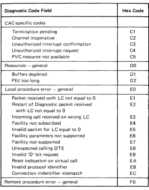
Cause Codes (Use Field Received from the OCE) 2-9 Oiagnostic Code Fields Received from the OCE 2-10 Diagnostic Code Fields Generated by an IBM (SNA) OTE 2-10
Summary of Counter Definitions by Log Type 3-5 CCA BSC Operation Attempted Chart (Code FF) 3-7 CCA BSC Operation Ending Chart (Code CCCC) 3·7 Sense Byte Breakdown Chart for CCA BSC
(Code SSSS) 3-11
CCA/HPCA SDLC Operation Attempted Chart (Code FF) 3-11
CCA/HPCA SOLC Operation Ending Chart (Code CCCC) 3-13
Sense Byte Breakdown Chart for CCA/HPCA SOLC (Code SSSS) 3-15
Sense (SS) Byte Definitions 3-17
Type B Adapter Operation Attempted Chart (Code FF) 3-17
Type B Adapter Operation Ending Chart (Code CCCC) 3-18
X.21 Switched Log Settings 3-21 Subsystem Configuration 3-30 Test 6 Byte 10 Chart 3-44 DCB Bit Definition Chart 3-44 IML Test Error Indications 4-1 AL T 1 IML Sequence 4-2
AL T 2 IML Sequence, Models with Wrappable Modem 4-2
AL T 2 1M L Sequence, Models without Wrappable Modem 4-3
A 1 02 Card I ndicator for 2400-bps Integrated Modem (Model 51C Only) 4-3
4-6 4-7 4-8 4-9 4-10 4-11 4-12 4-13 4-14 5-1 5-2 5-3 5-4 5-5 5-6 5-7 5-8 5-9 5-10 5-11 5-12 5-13 5-14 5-15 5-16 5-17 5-18 5-19 xiv
A 102 Card I ndicator for 4800-bps Integrated Modem (Model 51C Only) 4-3
A 102 Card Indicator for 9600-bps Integrated Modem (Model 51C Only) 4-3
3274 Model 51C, 52C, and 61C Online Tests 4-4 Operator Codes 4-6
Dump Procedure Error Codes 4-10 incident and Refiected Waves 4-12 Scope Setup 4-13
Measurement Points 4-13 Display Examples 4-14 Command Codes 5-1
Buffer Control Orde~'s and Order Codes 5-3 United States EBCDIC I/O Interface Code for 3274 Control Unit and Attached Category B Devices 5-5 United States EBCDIC I/O Interface Code for 3274 Control Unit and Attached Category A Devices 5-6 United States ASCII I/O Interface Code for 3274 Control Unit and Attached Category A Devices 5-7 Format of Write Control Character (WCC) Byte 5-8 Function of Write Control Character (WCC) Bits 5-8 Attribute Character Bit Assignments for 3278s 5-9 3278 Top-Card Connector CE Jumper (Three Base Cards) 5-9
3278 Top-Card Connector CE Jumper (Two Base Cards) 5-9
Attribute Character Bit Assignments for 3277s 5-10 Control Character I/O Codes 5-11
3279 Top-Card Connector CE Jumper 5-12 3279 Base Field Attributes 5-12
3274 Message Response to Polling or Read Modified Command 5-13
General Poll and Specific Poll, Sequence/Response Diagram 5-14
Selection Addressing, Sequence/Response Diagram 5-16
Write-Type and Control-Type Commands, Sequence/ R espo nse 0 iagram 5-18
Read-Type Command, Sequence/ResrJonse Diagram 5-20
5-20 5-21 5-22 5-23 5-24 5-25 5-26 5-27 5-28 5-29 5-30 5-31 5-32 5-33 5-34 5-35 5-36 5-37 6-1 B-1 C-1 C-2 C-3 C-4 C-5 D-1 D-2 0-3 D-4 D-5 D-6 0-7
Remote Status and Sense Byte Definitions, BSC 5-23 Remote Error Status and Sense Responses, BSC 5-24 Remote 3270 BSC Status and Sense Conditions 5-26 Nonsequenced Commands and Responses Supported by 3274 5-28
SDLC Commands and Responses in Hexadecimal Notation 5-29
Session Control Functions Supported by 3274 5-30 Data Flow Control Requests SUf)ported by 3274 5-30 Transmission Header Format 5-30
Request/Response Header Format 5-31 SDLC/SNA Commands Required to Start Session with LU 1 5-32
SDLC/SNA Exception Responses 5-33 Summary Table of LUSTATs 5-37
Command Reject (CMDR) Message Format 5-39 Switches and Controls 5-41
BSC Readiness Symbols 5-42 SNA Readiness Symbols 5-43
Connection of 3274 Control Unit with DDS Adapter Feature 5-44
Digital Data Waveshapes 5-45 TPLM Tab Pin Locations 6-1
Correlation between Indicator Codes and Log Area B-38
Data Link Control Function C-1
Keyboard Layout with X.21 Switched Feature C-4 Key Operation (During X.21 Switched States) C-5 Key Operation in Dial-In Mode C-6
Call Progress Signal Code C-6
Control Unit/Terminal Responses in Dial-In State D-6
Key Operations During X.25 States D-9 Extension Mode Definition 0-13
Extension Key and X.25 Function Keys 0-14 Dial IVf<>de Display Layout D-15
Chapter 1. Maintenance Approach and System Overview
This chapter contains information to assist the support
customer engineer in isolating and correcting 3274 sub
system problems that cannot be attributed to a fail ing
field replaceable unit (F R U). The information supplements
existing documentation cbvering problem isolation, use of
serviceabil ity aids, special ized tools, and test equipment.
The topics presented include the following:
• Overall Maintenance Approach: The maintenance
approach is outlined to provide flexibility both in the
type of approach taken and in the selection of
support-ing serviceability aids. The maintenance approach
identifies and refers to procedures, tests, special ized
tools, and test equipment that will most I ikely help
isolate various types of 3274 problems. Detailed
descrip-tions of these serviceability aids and their use are
con-tained in other chapters in this publication. In addition,
examples using these serviceability aids are given for
typical
3274 problems.
• Subsystem Operation Overview: This overview gives a
general description of 3274 operations and functions.
• Serviceability Aids: A general description of service·
ability aids and their use is given. These aids include the
operational indicators, display symbols, error suffix
codes, logouts, tests, test equipment, and host error
recording.
• Reference Material: Aii supporting reference material in
this publication is identified and described. This
refer-ence material provides detailed descriptions of error
recording and indications, tests, error recovery pro·
cedures,
3270"3274 operational differences, error suffix
code action chart, and tools and test equipment.
• Procedure for Requesting Assistance: A procedure for
requesting assistance from the next level of the support
structure is outlined. This procedure includes 3274
problem recording which wi" aid the support structure
in problem determination.
• Supporting Publications: Supporting IBM publ ications
are identified.
1.1 MAINTENANCE APPROACH
This maintenance approach is outl ined to provide
flexibil-ity both in the type of approach taken and in the selection
of supporting service aids. The approach used to isolate a
specific
3274 problem may vary because of multiple error
indications and the type of operation being performed at
the time the error occurred. Therefore, the following
maintenance approach to typical problems is not
necessar-ily the only effective approach that could be used.
The suggested maintenance approach identifies and refers
to various procedures, tests, tools, and test equipment that
wi" most likely aid in isolation of the problem. This approach
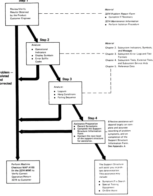
has four basic steps, which are performed in sequence:
Step 1
Review and verify the results obtained by the product
customer engineer by using the following reference
material:
• 3274 Problem Report Form
• 3274 Control Unit Maintenance Information
Step 2
Analyze operational indicators (84 2 1), display symbols,
and error suffix codes (nnn
codeS).
Step 3
Analyze logouts, hang conditions, and failing operation
sequences.
Step 4
Record all problem symptoms, and complete the Support
Structure Information Form in preparation for requesting
assistance. The effectiveness of the assistance wi II depend
largely on the information that you provide.
These four steps are illustrated in Figure 1-1.
Step 1
RevievvlVerify Results Obtained by the Product Customer Engineer
Problem
-Isolated
and
Corrected
Step 2
Analyze: • Operational
Indicators • Display Symbols • Error Suffix
Codes
Perform Machine Checkout MAP A 100 (in the 3274 MIM) to Verify Correct Operation/Return 3274 to Customer
Step 3
Analyze: • Logouts
Material
3274 Problem Report Form • Complete If Necessary 3274 Maintenance Information • Perform Isolation Procedure
Material
Chapter 2. Subsystem Indicators, Symbols, and Messages
- Chapter 3. Subsys~em Error Logs and Test Formats
Chapter 4. Subsystem Tests, External Tests, and Subsystem Service Aids Chapter 5. Reference Data
I
I
I
I
I
.-J
• Hang Conditions• Failing Sequence
Step 4
Assistance Preparation • Record Symptoms • Complete the Support
Structure Information Form
Effective assistance will depend largely on com-plete and accurate recording of problem symptoms, and on completion of the Support Structure Information Form. • Contact the next level
of the support structure for assistance.
See Appendix A
The Support Structure will assist you in prob-lem determination. This assistance may include:
• Symptom/FIx Search • Special Testing
Equipment • On-Site Assist
Figure ,.,. Support Customer Engineer Maintenance Approach
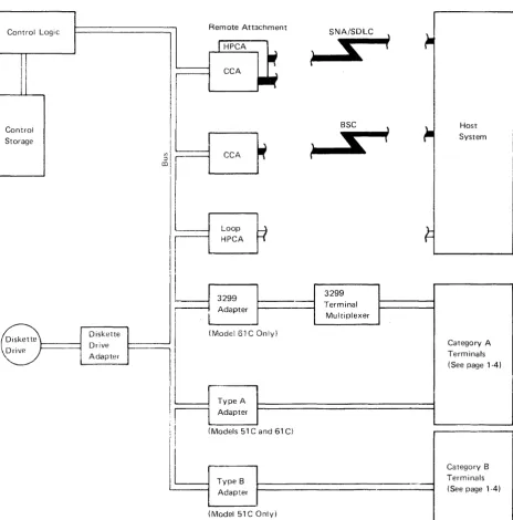
[image:16.612.37.529.65.695.2]1.2 SUBSYSTEM DATA FLOW
[image:17.615.82.547.254.724.2]The
3274
subsystem data flow consists of test data;
con-trol data (unit code); status, error, and log data; and
mes-sage data between the components of the subsystem.
Figure
1-2
illustrates the
3274
subsystem configuration,
including use of the
3299
Terminal Multiplexer on the
Model
61
C. The data flow is described as follows:
• Initial Machine Load (lML) of Test Data - Loading the
1M L test data resid ing on the system diskette into
con-trol storage (paragraph
1.2.1
and Figure
1-3).
• I
nitial Mach ine Load
(I
M L) of Unit Code - Loading the
unit code residing on the system diskette into control
storage (paragraph
1.2.2
and Figure
1-3).
• Message Data Flow between
3274
Control Unit and
Attached Devices - The flow of message data between
the
3274
Control Unit and attached devices (paragraph
1.2.4
and Figure
1-4).
• Message Data Flow between
3274
Control Unit and Host
System - The flow of message data between the
3274
Control Unit and the host system (paragraph
1.2.5
and
Figure
1-5) .
• Status, Error, and Log Data Flow - The flow of data
from the
3274
Control Unit, the host system, and
attached devices to the data control block area of
con-trol storage (paragraph
1.2.6
and Figure
1-6),
Control Logic Remote Attachment SNA/SDLC
Control Storage
Diskette Drive Adapter
CCA
,...-_:_L_oo_p_..,.b _. HPCA
I'
3299
Adapter
(Model 61 COnly)
I
IF
:I TypeA AdapterS
BSC
s
3299
Terminal Multiplexer
\
i
)
t
Host System
Category A Terminals (See page 1-4)
I'
II
(Models 51 C and 61 C)II~
__
~T-y-pe-B~~
_ _ _ _ _ _ _ _ _ _ _ _ _ _ _ _ . _ Adapter(Model 51 COnly)
Figure
1-2. 3274 Subsystem Overview
1.2.1
IML Test Data Path
The IML test data path is shown in Figure 1-3. IML test
data is retrieved from the diskette drive and the diskette
drive adapter after 1M L tests 0000, 0001, and 0002 have
been successfully completed. 1M L test 0002 verifies that
the diskette drive and the adapter are functionaliy
opera-tional. The data path, from origin to destination, is
identi-fied as follows:
• Diskette Drive
• Diskette Drive Adapter
• Bus
• Control logic
• Control storage
Control Logic
)
Control Code
~=:::::~~=~
Area~I::_~ Diskette Drive ~~I!!!.J Adapter
Figure 1·3. Initial Machine Load (lML) Data Flow
'·4
1.2.2
1M L of Unit Code
The data path of IML (loading of unit code) is the same as
the IML test data path. Unit code is normally loaded after
the IML tests are successfully completed. Placing the AL T
switch in the ALT
1
position and pressiny the IML
push-bUl ton wiii cause the iM L test to be bypassed and initiate
loadiny of the unit code.
1.2.3
Category A and B Terminals
The terminals that attach to the 3274 Control Unit are
characterized by group, (Category A and Category
B),to
reflect the type of adapters they are attached to, within the
3274 Control Unit. The 3274 adapters are referred to as
Type A
or
Type B.
Listed below are the 3270 terminals
and their respective groupings:
Category A Terminals
3178 Display Station Models Cl, C2, and C3
3179 Color Display Station
3180 Display Station Modell
3230 Printer Model 2
3262 Printer Models 3 and 13
3268 Printer Model 2
3270 Personal Computer
3278 Display Station Models 1, 2, 3, 4, and 5
3279 Color Display Station (all models)
3287 Printer Mode!s 1, 1 C, 2, and 2C
3289 Line Printer Models 1 and 2
3290 I nformation Panel
4250 Printer
5210 Printer Models GOl and G02
Category B Terminals
3270 Personal Computer XT /370
3277 Display Station Models 1 and 2
3284 Printer Mode!s 1 and 2
3286 Printer Models 1 and 2
1.2.4 Message Data Flow between 3274 Control
Unit and Attached Devices
Message data flow between the
3274
Control Unit and
attached terminals is shown in Figure
1-4.
The message
data paths, from origin to destination, are identified as
follows:
3274 Control Unit
to Terminal
• Control storage
(message buffer area)
• Control logic
• Bus
• Type A or B adapter
• Category A or B device
Control Logic ~ Remote Attachment
SNA/SDL~-r
II1II'
-lHPCA
~
~
S
•
II1IICCA
.~
•
~.
~~
Control
~
Storage
~
BSC \~.,~ ) Message
S
l
~-
BufferII
~
1
--
Area CCA,
~
~I
Loop
Fl
HPCA
I
3299
I
J
3299I
I
Adapter J Terminal I
I
MultiplexerI
(Model61C Only)L.
8=
D;skette D,;veDrive Adapter
,
Type A Adapter
(Models 51 C and 61 C)
-
Type B
~Ir-'---.-
9
Adapte, I·
(Model 51 COnly)
Figure 14. Message Data Flow between
3274
Control Unit and Attached Devices
Device to 3274
Control Unit
• Category A or B terminal
• Type
A
or
B
adapter or
•
3299
Terminal Multiplexer
•
Bus
• Control logic
• Control storage
(message buffer area)
~
~
System Host~
I
I
Category A Terminals (See page 1-4)
I
I
Category B Terminals
i
.2.5 Message Data Flow between 3274 Control
Unit and Host System
Message data flow between the 3274 Control Unit and the
host system is shown in Figure 1-5. The message data paths,
from origin to destination, are identified as follows:
Control Logic
,
..
Remote AttachmentI
HPCA--
...
eCAI
~Control
~
Storage
~J
) Message Buffe,
~~
...
~~~..4 co
---
Area ~....
CCA
i
i
I
i II
I
Loop----HPCA
I
3299
Adapter
(Model 61 COnly)
Diskette Diskette Drive Drive
Adapter
Type A Adapter
(Models 51 C and 61 C)
Type B Adapter
(Model 51 COnly)
3274 Control Unit
to Host
• Control storage
(message buffer area)
• Control logic
• Bus
• Remote host adapter!
local channel attachment
or local host attachment
• Host system
SNA/SDLC
S
....
SSC
I
...
~---3299
Terminal Multiplexer
Figure '·5. Message Data Flow between 3274 Control Unit and Host System
1-6
Host to 3274
Control Unit
• Host system
• Remote host adapter/
local channel
attach-ment or iocai host
attachment
• Bus
• Control logic
• Control storage
(message buffer area)
Host System
Category A Terminals (See page 1-4)
1.2.6 Logic Data Flow
Status, error, and log data flow is shown in Figure 1·6. The
data paths, from origin to destination, are identified as
follows:
Host System
• Remote host adapter
Control Logic
~,
Control Storage
~
)
Diskette Drive
Category A and B Terminals
• Type A or B adapter or 3299 Terminal Multiplexer
• Bus • Control logic • Control storage
(control block area)
II)
:::l
co
Diskette Drive Adapter
FIgure 1 6. LogIC Data Flow
.
31SDor51TD
• Diskette Drive Diskette Drive Adapter
Remote Attachment
I
HPCAIf
CCA
.~
CCA
if
Loop
:I
HPCA
3299 Adapter
(Model 61 COnly)
I
,
Type A Adapter
(Models 51 C and 61 C)
Type B Adapter
(Model 51 COnly)
SNA/SDLC )
it-I;
i
l
BSC \
1-
HostS
i
System\
,
U
3299 Terminal
Multiplexer
Category A Terminals (See page 1-4)
Category B Terminals (See page 14)
1.3 SUBSYSTEM FUNCTIONS
The 3274 subsystem provides the following functions:
Function
Description
o
1
2
3
4
5
6
7
Machine check/program check activity
I/O operations to and from the host CPU
Diskette Drive operations
I/O operations to and from Category A and
Category B devices (Category B devices do
not attach to Model 61 C)
Device feature functions
Messages sent to the host CPU
Messages received from the host CPU
Initialization (POR and IML)
These functions are illustrated in Figure 1-7.
Control
Storage Control Logic
See Note
Function 0
Machine Check and Program Check Activity
Function 7
Power On Reset (POR)
and Initial Ma~hine
Load (1M U Operations
Function 2
Diskette Operations
I nitial Machine Load (IMU
Diskette Drive Adapter
Bus
Note: The functions shown in this diagram are provided by the control logic.
Figure 1-7. 3274 Subsystem Functions
1-8
CCA/ HPCA Adapter
To describe the 3274 unit functions in more general
terms, they may be grouped into six basic categories:
(1) Power On Reset (POR) operations, (2) key-tracking
(moving data from the keyboard to the display screen),
(3) receiving from the host, (4) sending to the host,
(5) error handling and logging, and (6) internal testing.
Function 1 I/O Operations to and from Host CPU
Function 4
Device Feature Functions (MSR, etc.)
Function 3
1/0 Operations to and from Category A or B Terminals
Function 5 Messages Going to Host CPU
Function 6
1.3.1 Control Unit Power On Reset
When the 3274 is powered on, the Power On Reset (PaR)
signal is generated in the power supply. The paR to the
logic board generates a restart to the control logic and,
sub-sequently, starts a normal 1M L sequence. If two power
supplies are installed, the paR from each supply is
con-nected to the other in the logic board. (See the 3274
Con-trol Unit Models
51 C
and
~2CMaintenance Information
manual, SY27-2513, or the 3274
Control Unit Model61C
Maintenance Information
manual, SY27-2555.)
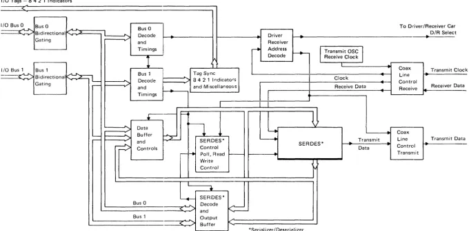
1.3.2 Keystroke Handling
The requests and status from the attached devices are
handled by the Keystroke control function. When an
operator presses a key, the keyed data is read by the
dis-play base card
1,
which, if it receives a po", sends the
data to the terminal adapter (Category A devices
only). The terminal adapter then loads the status
and scan code of the actuated key into a queue.
The terminal adapter control retrieves this
infor-mation from the buffer queue.
Keystroke control converts the scan code and distributes
the data to the appropriate functions. See Figure 1-8 for an
illustration of Type A adapter keystroke handl ing.
As an example of keystroke handling, when a graphic
character key is pressed, the graphic key scan code is
con-verted into internal code and then into regen code by
means of a language code conversion table. The converted
regen code is moved into the device regen buffer
iafter
which the graphic character keyed may be seen displayed
on the screen.
When a device is polled, if it has an error condition or
request from a feature (selector pen, MSR), it sends status
to the terminal adapter, and key tracking control handles
the status as it does a status preceding keyed data.
An error condition detected by the device is signaled to
the terminal adapter when the device is polled. Error
con-ditions are (1) device check (a parity error was detected in
the regen buffer), (2) keyboard overrun (keystrokes too
close together), and (3) feature timeout (no response from
the feature card within the expected time).
Special keyboard scan codes are used for the device
paR signal and keyboard overrun conditions. Selector-pen
data is sent to the terminal adapter by read commands. The
row count is sent on the first read, and the field count is
sent on the second.
•
..:... To Control Logic
a
I/O Tags - 8 4 2 1 Indicators
<:
I/O Bus 0
..
...
Bus 0 ... ... Bus 0 To Driver/Receiver Car-.-~ Bidirectional K 2
I
...
D/R SelectDecode ~
..
Driver ~Gating and Receiver
1... _ _ _ _ _
Timings I ---to Address
l
Transmit OSC
j
---1
I."
Decode Receive Clock I..
I/O Bus 1 Bus 1
I
Coax Transmit Cia---~
~~
Bus 1 Tag Sync~
Bidirectional Line
....--v
...,.....
Decode 842 1 Indicators Clock ~Gating r - Control
and
.
and MiscellaneousI
Receive Data Receiver Oat~ Receive
Timings
1
....ck
a
+
i---<.
Datan
..; ~
.
Buffer.
Coax'
-
P=-r - -
'"
and SERDES* ~ Transmit Line Transmit Oat~
Controls Control SERDES*..
Data.
Control-
~ PolI,Read ~- Transmita
Write Control
L
SERDES*-.
Bus 0...
Decode<=-<
.>
andBus 1 Output ...
L . o - - .
.
~
Buffer*Serial izer/Deserial izer
[image:24.793.64.745.61.397.2]1.3.3 Sending to Host
Data from Category A devices is queued via function 3
into various bu ffer formats, depend ing on the type of
host attachment used, by the device control code. The
data is then handled, again in queued buffer formats,
by the data stream control code. The host processing
control code then forwards the appropriate data from
another queued buffer to the host. (See Figure 1-9,)
Input Messages from Device
Function 3
...
~
,..
Device 1/0 Operation
Function 5
~
Outbound Message
Function 1
...
r - - - ~
Host Adapter
4
Output Message to Host CPUFigure 1-9. Inbound Messages
1.3.4 Receiving from Host
Data from the host is queued via function 1 into common
transmit/receive buffers of various formats, depend ing on
the type of host attachment used, by the host processinr
control code. The data is then handled in queued buffer
formats by the data stream control code. The device
con-trol code then forwards the data to the device. (See
Figure 1-10.)
Host Line Intedace Inbound Me"age
I _
'---_FL._'nctio_n 1
_~L
j
_ Host Adapter
r
Function 6
I
Inbound M essageI
Function 3
I..-....
Device I/O Operation
~ Output Message to Device
Figure 1-10. Outbound Messages
1.3.5 Error Handling and Logging
Error handl ing and logging is performed by the control
logic and storage. Log statistics and information are
available for each device and host adapter by means of
test procedures.
1.3.6 Internal Testing
All internal tests are performed by the control logic, and
indicators are provided for test results. Host support is
not required for internal testing.
1.3.7 Function Priority
The priority scheme used by the 3274 subsystem is
illus-trated in Figure 1-11. Function
a
has the highest priority,
and function 7 has the lowest priority. For example, if a
machine check (function 0) and a file operation
(func-tion 2) are both pending, the 3274 controi iogic performs
function 0 followed by function 2.
Function 0 Machine Check and Program Check Activity
Function 1 Setup Operations to and from Host CPU
Function 2 Diskette Operations
Function 3
Setup Operations to
dnd from Category A or B Devices
Figure 1·11. 3274 Subsystem Functional Priorities
1-12
Function 4
Device Feature Functions (MSR, etc.)
Function 5 Messages Going to Host CPU
Function 6 Messages Received from Host CPU
1.3.8 Type A Adapter Coax Data Path
Figure 1-12 illustrates the bit path from the coax to the
Type A adapter.
Adapter States
1. Disabled
2. Enabled but Idle (Normal Polling) 3. Enabled Working (Passing Normai
Data/Keystroke Activity)
Note: When a 3299 Terminal Multi-plexer is attached (TM Type A Adapter), the driver/receiver is modified and a single coaxial cable connects the Type A adapter and the 3299 unit
Control
Logic and
...----1
StorageOperator Panel Indicators
Type A Adapter
I/O Buffer
SERDES
Driver I Receiv8r
Bit Serial Coax
~II
\
I
\
10 Devices
Figure 1-12. Coax to Type A Adapter Data Flow
Bit Parallel
1.4 SUPPORTING PUBLICATIONS
The following publications should be available for reference.
• System Description
3274 Control Unit Description
findProgrammers Guide,
GA23-0061
• Customizing
3274 Control Unit Planning, Setup, and Customizing
Guide, GA27-2827
3274 Control Unit Customizing Guide, GA23-0065
• Maintenance
3274 Control Unit Models 51C and 52C Maintenance
Information, SY27-2513
3274 Control Unit Model61C Maintenance Information,
SY27-2555
• Setup
3274 Control Unit Model 51C/61C Setup Instructions,
GA23-0047
• Quick Reference
3274 Subsystem Customer Engineering Reference
Summary, SX23-0207
Chapter 2. Subsystem Indicators, Symbols, and Messages
2.1 iNTRODUCTION
This chapter provides information concerning the operator
panel indicators and the Category
A
display symbols and
messages used to convey error and subsystem status
condi-tions to the user and the customer engineer. The operator
panel indicators include the 84 2 1 indicators and the
Power On/Off indicator.
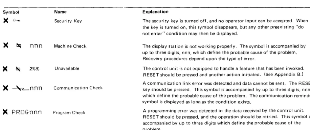
The subsystem symbols and messages displayed on the
status line include the Readiness and System Connection
symbols, Do Not Enter messages, Communication
Reminders, Shifts and Modes symbols, Prin