REPORT
NUMBER
(CO(OO
PEPl'PT OATF 04DFC74,VOL DO? ,...,/1
3411
SFPTAL 51051905LOGIC
NUM8FPDESCRIPTION
PA RT NUM 9FP EC NtP~B fR FFA TURE ~!I~SYSTEMS OIAGRAMS
XJ 00 1 0
VOL
? TARl~ 0FCCNTENTS
OC0184SQ91 0(0734852
X~ 01 00
3"1') /11 1 NS TA lL
rl1FCI(SYEET
0001846000 0(0736672
STABILTZEP L BRACKET INSTAlLA
OOO18
L6001 rC07jL,·732
X"lO~C0 TAP f UN
ITS
1 G N ALe ,A A L F D UJ ~r;
I OODl ,34t 002 000736672XQ0020
fAPQl TABLE
(C CC~T~NTS0001846003 (00734864
X()0050 ~ENEPAL
lO(ATInNS
OOO1845
Q77 000734732
XQOIOO
OC01846004- 00073L..864
XQ 02 0') TAPE
LCOP
CYfCK0001846005 0OO73A672
XQ03CO
TnpCOVEP
DFMOVAl
&
0EPlACE~EOOO184AOO6
0007":34852
X00400
SLIDING DnnR RFMOVL A REPLACE
0C01846007
(:[07348114X()C50C QP
PANEL
lA~PREMOVL.& RFOLA
0001.846008 000734852
XQC600
0001846009
000734864XOC7CO
lSAGF
MTqTRFMR
REMDVl
&
REPL
0001846010 000734864XQC8CQ
FILE PRnTFcT SW REMnVl
~RFPL
0001846011 000734864
XQ C9C
f) TF R MIN ALP nAP n & F USE L r.r AT I 0oon186.6012
0007348f4
XC 1. CO 0
NnTION
(TPL RD
REMOVL PFMPLAC
0001846013 COO736672
XQ1100
REEL
MTP FUSfS
RE~nVlREMPLAC
00018L..6D14
C00734864
X01200
TAPE InlER
ASsv-REM,qFPl
AOJU
OCO 18l;.6 0150007366
72
REPORT NUMBFR
o(coeo
PEPnPT DATE 040EC74
VOL r 02 MIT 3411 SJ:RTAL 51051905
LOGlC
~UMRFROES(QTPTlnN
DART
NU~REREC NUMRFR
~EATURE3M
S Y ST F M S !l I A G R.A M S
XOi250
0001846042 0[0736672
XO 1 3C C
R01/FOT
ASSY-RF~,PEPl ~ADJUS
0001846016 000735117
XQ1400
VA.C UUM CHEC KPR.nc
FOUJ:<E S0001846017 000734864
REA S
0005118589
XQ1450
TAPE
LnAO CHECK ANDADJUSTMENT
0001846043 000734861
XQ1475
VAClJUM
COLUMNREMOVAL/REPLACEMFNT
0001846046 000736A72
)(01500 VAC UUM PUMP
0001846018 000734852
X()1600
VACUUM PUMP PEM
& REPL
0001846019 000734864
XQ1700
VACUUM MOTOQ ASSV REM
~PEPl
0001846020 000734852
XQ 18CO
CAPSTAN MOTn?
ASSY
REM
3 PEPl
0001846021 0007348'52
X01900
TAPF TRACKING
CHECK & AOJUSTM
0001846022
0OO73t..852
)(02000
REEL LATCH ASSY ?EM
~REPL
0001846023 000736672
X02100
REEL HUR nlTGNMFNT
0001846074 000734864
XQ2150
R/W HEAD CAPO
0001846051 000734864
X02200
3411 EXHAUST FAN ASSY
RE~REP
0001846025 C00734852
XQ23CO
DC POWER SUPPLY COLING FAN A
0001846026 0007348'52
X02400
CP1,CP2
&
CP3 CIRCUIT PROTECT
0001846027 000734852
XQ2500
4-VDlT ASSV RFM
gRFPl
0001846028 0007342S4C
TABLE
nF
CCNTFNTS
REPORT
~U~R~D000(00
vnt nc?
~~/T 7411l
r
r, 1 C i\J IJ~~ R ? f:, nc:
<:( DIP T I (V~SY5TFMS
DIASRAM<:XQ2 60 0 ooal~4~02~
C0173A672
XI) 2 7 C C 0001R4~030 00073667?
X()2800 00018~6031 00n7]4864
X()29C,)
AC
fERROCAPACITORS
0001846032 0007?4852x(30)O
MFrH 8. EU::CT S!<E WAf)JUSTfIflENTS
OC0184~03;000736672
XQ3100
MFCH ~. E LI= C TSKEW
AOJUSTMFNTS
0001846034 000734852
fAEC H ~
r:U=CT
SKI=W
A 0 JU S T ~F NT SXO?300
M[=CH 8" ':lcCTSKEW
An JU S T M!= f\IT S0001346036
000734~52XQ34CO MI=CI-i ~
El!=CT
SKF~J ADJUSTMEf\ITS0001846037 000736672
X034~O
0001A
46145 G007348~2XQ3~CO
000lB46038
OC~734556XTOIOI)
SENSE RYT!= PROfFOuqcs SYS'20001846091
00073~~52XT 02 ( Q
HOW
Tn
RUN
EREP
SYS
360/170X\..J 01 JO SFPVICF TFCHNlnUFS
00018&f093 000734556A
XWQ2aO
OOOlR&6094 C
n0734556
XWJ3CO
MICROPOOCESSFRTESTfR
KIT OOOlQ4609SOC0734P52
XW040'J
MICRopqnCFSSER TESTeR OP INST
0001846
096 000736672
XW0500 q 0 SPA TC H (A P 0
0001846097 C00734556A
TARLE OF
CrNT~NTSR~PORT
NUMBER
OCOOOO
RFPOPT DATE 04DEC74
VOL 002
MIT
?411
SEPTAL 51051905LOGIC
NUMBER
DESCRIPTION
PART NUM SF. RFe
NUMB FPFEATURE
8MSYSTEMS DIAGRAMS
XW06CC
ROS PATCH
CARDOOOlR46C9S C'OO7345C)6A
XW07CO
RPS
PATCH CARD
0001846099 0OO734556A
XW08CO
~OSPATCH eARn
0001845897 C00734556A
XZOICO
INDEX 1
0001846039 000736672
XZ0200
INDEX 3
0001846040 (lOa 736672XlO~OO
INDEX 5
0001846041
;')(0736612XZ2CCO
READERS
CO~MENTSFORM
0001846100
0007345'56~.'---3411CU---______ -i.~:~4~---3411TUand3410---~.~
!
I
m n (X) A en w VG108 ~---, Power.()n Pushbutton EPO ContrOl...L
_IL_oca __ I_' _________ OPower Pick
IRemote'
ISystem/360/370 Only
When connected to a Svstem!3 or Svstem/3B. the subsystem has no local power control. Power is turned on and t)ff from the system.
.'.
All power supplies Me located to the 3411.
AC Connectors
FIle Protect
SwItch EOTiBOT
-rlh
-_lo-_ ... __ .. _ ....
~J_'-tThrOUgl"h_J6
... _ _ "~:;U;;::tr
~ MeterXFMR.3410
[!!l
~
Single· Phase Power
Power Supply Fans 41VAC To Meter (341H VC001 -15 VDC
.,5
VDC VGltO ·GVDC (Adjustablel YG110 VG115 To: 3411 Fans VG105 .WB800
OC TB 1 iCications are connected to component locations by
jumpers. The number keys indIcate whIch Tal locallOns supply voltages to each
component locatIon.
+5VOC
D
(Pm 111 ______ ...(Pm 31 5V.6V
(Pm 4 ' -Common
(Pm 11 +6VDC
(Pm 21
f.J
EI
a
m
m
D
m
(Pm 71 .,5VDC
I - - - ( P I O 8) ' - - - , " "
m
1m
m
[pJ
m
RMdlWrite PM:Qge VKuumTB5 (Relay Coill[!]
l5V
Flllef
Flltertng for the 15 volt sLopphes IS separated from the 3411 power supply. and is located on each drive.
-·4 VDC IAdJuSldbiel
YG120 DC ConneClon
J21 Through J26 (P",51 (PIn 6)-Common 15V
[Ct----....
No power sequenclOg IS prOVIded.
To COnlrol UnIt Gate
+6VDC
(Adjustab;e) ... t
-YG110
Power SupplIes
lm
IPin 91 ---;"';";--' . . --1 ~IPIO 101 ~
m
ml
lm
fE
15V FIlter3410/3411 DRIVE AC/DC DISTRIBUTION OCTal
Read/V"',. T84 LogiC: Board Operator Panet
I
) ..
e
ReadlWrite
Deskew Boerd
D
II
15V DIstribution For Each
Tape Unit
•
•
•
• • •
•
• •
• • • •
•
• •
•
•
•
•
• • • •
• •
•
•
• •
• •
•
•
___ r - ~. _
-
- -
.-..-
. --
---
---
~ ~-~-- - -
- -
---
.-==. .:::..::..
5 5 5 :
=-=~==-==
-===-=
=
-=-
=
-
----
--
_
--
...
--
--
.---
-
-
-
-- .
-- -
--
~--
-- -- -- --
- -
---- ---- ----
-
-
~--
--
-- --
---
---
--
--Magnetic Tape Subsystem
Maintenance Manual
::====.
--
-
-
-
- -
- -
--
-
= .
--
----
-
-
---- ----
-
----~--
---~--
--
- .
Volume'
PLAN
I NTRO
ductionMAP
~an
MAP
AAxx,MAP
ABxxxMAP
ACxxxMAP
AOxxxMaintenance Library
Volume 2
D I AG
System/3 User's GuideINSTALlation
Checks
CA R R L
AdjustmentsRemoval/Replacements
Locations
REF
erenceS E R
vIce Techniques)
) )•
• • • • •
•
•
•
•
•
• • •
•
)
)
The IBM 3410/3411 Diagnostic User's Guide (System/3) is being shipped from Boca Raton, Florida for domestic use and from Vimercate, Italy for
World Trade Corporation, with the diagnostic routines. lnsert the System!3
User's Guide following this page .
•••
••
•
•
•
'.
Note: See INSTAL 2A for 3750 Installation checksheet.
~~IT~E~M~ __ 4-______________ N~O~T_E~S~ __________________ +-~T~C~T~U~O~_T~U~1~~T~U~2~~T~I.J~3~~T~U~4~~T~U~54
I
I
Placement of 1 Install stabdlzer·L·· brackets See Figure 2
Uniu 2 Lowe,. rear stabilizer ··L· brackets untt! they lust tou;;h the floor. and thf'n ltghten the mounting screws 3. M<XJnt the side COllers loowly. In proper confl~.Hatlon. See "Side Covers" In this chart.
4 POSItion units according to customer reQuirements. Not.: Due to the ler'9th of the 3410 cables. not more than th ree 34 1(}; can be Installed on either Side of the 3411. 5. After machlf,es are In place. snug front stabilizer' ·L·· bracket mounttng screws
6.lnsert large screwdriver through c Jnter hole of bracket and pry downward untd bracket firmly but lust contacts !he floor Do not raise casters oH the floor
7. Finish tightening front stabilizer ··L" bracket mounting screws
Note: Do not raise trar-sport until all four stabilizer . L··
~ __________ ~~b~r~ac~k~e~t~s~a~r~e~fl~rm~IY~ln~p~ll~ac~e~ ____ ---1---t---~----i_----_t----~~----t_---.-Shipping 8rackeu Altitude Setting Model Numbers
Tape Unit
Futu ....
Side Covers
1
1 Turn vacuum system hold-down bracket approximately 270 degrees clockWise around the frame screw. See altitude setting next section See also ··CARRL·· Figure 0-1. Item 28
2 With front cover oH. remove the screws located near each front corner of the transport casttng that fasten the transport hold-down brackets to the Side frame See . 'CARRL Figure 0-1. Item 29. For World Trade only. remove only the right hand screw The left hand screw must be left ,n place
Note: Do not remove transport hold-down brackets from transport casting. Leave them In place for reshipment 3 Remove filament tape from the 3411 gate latch 4 Remove filament tape from all cables
For operatIon at altitudes above 3.000 feet (914. 4m). move vacuum supply drive pulley so belt IS driven by large sheave of drive pulley
See ··CARRL" Figure 0-32. "Vacuum Pump Remol/al and Replacement Procedure.
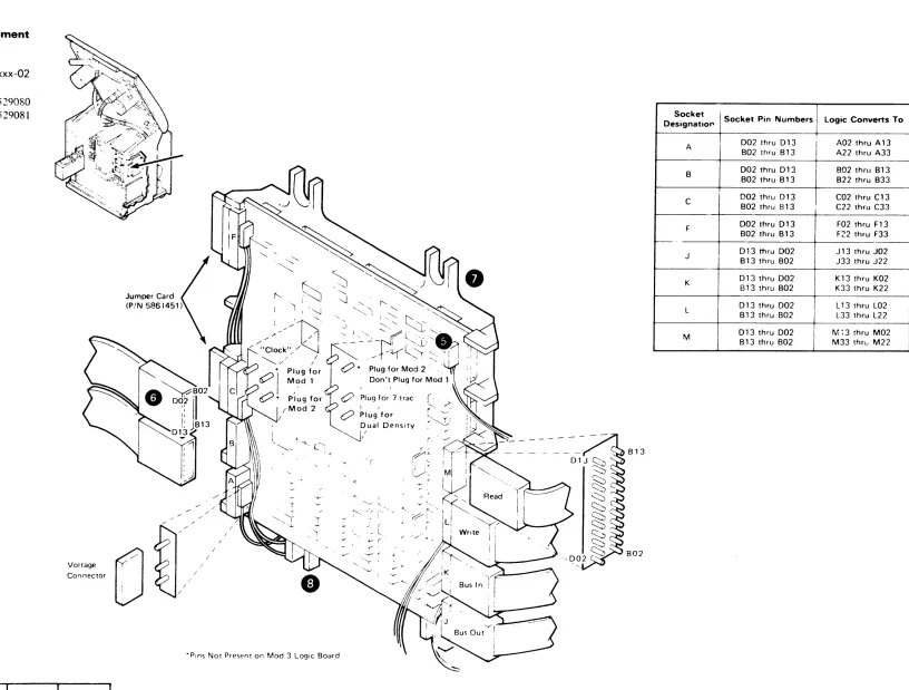
Verify that all 3410 tape unIts in the subsystem are the same model number as the 3411 Refer to Figure 3 to verify model number ;>luJHlIna.
Jumpet's for the tape untt features are fac~ory-plugged on the logic board See FIgure 3 if the diagnostIc pnntouts indicate posSIble pluggtng errors In thIS area.
Note: Tape units must not be plugged for a feature unless both they and the tape control to whIch they are attached havp this feature installed
1 Open the slidIng door CAUTION
To prevent top cover damage. always use the lifting bar to raIse the transport assembly Be sure both support brackets latch; one bracket may require manual latching
2. RaIse transport by grasptng the liftIng bar located under the transport and lifting.
3 St"'::ure the side covers. (Install side covers Without oval cutouts at exposed ends of subsystem.)
Flexible Instali between units as shown In FIgure 4 Ensure on Conduits and System/3 and Svstem/38 only, both ends of I/O cable Ground ground are Installed
Straps
"CARRL - "Checks. Ad,ustments. Removals. Replacements, and LocatIons section of this manual.
•
•
•
••••
•
••
• • • • • •
••
• •
ITEM NOTES TC TUO TU1 TU2 TU3 TU4 TUI
Power Cables 1 Route all 3410 power cables through the flexible condUIts.
ROUTE ALL DC CABLES FIRST.
2. Plug de power cables (black) Into dc (red) sockets J21 -J2f3 tn 3411 power supply.
3. Plug ae power cables (gray) IOto ao: sockets J1 - J6 (white) 10 3411 ac box
For servicing convenience. plug cables from TUO Into sockets Jl and J21 and those from TUl into sockets J2 and J22. etc
Note: Any tape untt power cable ma.,. be connected to any socket WIthin the appropriate group See CARRl 0-56. TU 1 Venfy that 9142 card In A-A 102 has Jumper from Addressing P34-Q34. (TU addresses ~3)
2 Verify that 9142 card In A·A 1 E2 has Jumper from Q34-R34. (TU addresses 4.5)
See Al.D pages JA 101 and JA201. See . ·CARRL·· r'lgure 0-58 See ··INSTAL 2. ... "PE 10 Burst Check."
Signal Cables Route all 3410 Signal catlo!; !~rOUG~ fleXible condUits. Figura 4 Plug as shown In Ins~allatlo', Manual Figures 5 8:
6. uSing cable holder. part 819410. ;)n each bus Gut cable. Remove the "E·' card for ease of tnstallatlon of bus out cables on subsystems with the Additional Tape Unit Feature (#9001) (Customt1fS addresstng scheme determtnes pluggtng sequence) Captivate all cables under the cable clamp bar at the left Side of the controller gate. vIewIng from the card -SIde.
Cable After plugging power and Signal cables. place power cables Channels 'in the rear cable channel of each unIt. Place SIgnal cables
In the front channel Of each Unit. (The front channel IS the one With a foam p<ld In the bottom.)
~~
"Select Out" Machtnes are Wired at the factvry for "high" prlonty. To Priority wife for ··Iow " priority. chan~e wires as shown: (System/360
and System/
Note: Does not ap;-' to System 3701115, or 370/125.
370 only)
"High·' Prlonty "Low" Pnority A 184808 - A 1 A4808 A 184808 - A 1 F2P09 A1A4009 - A1F2POQ A1A4009 - A1B4009 A1F2P11 - A1B4009 A1F2Pl1 - - A1A4808
3411 Model Verify that cards in A 1 H2: Al J2. and A 1 K2 are plugged Identification accordIng to Tape Controlier ALD page A6001. CU Address Jumper card 01 A-A 1 M2 according to ALO page A6002. (System/360 Note: Does not applv to System 370, Models 115 and and 125 MTA. It does apply if MPX attached.
Syatem/370 only)
CU Busy System/3 and System/38 - Jumper 01A-A1G2 S49 to T49. 370/115 or 370/125 only, Jumper 01A-A1G2 U49 to T49. Metering System/3 and System/38 - Jumper 01A-A1G2 S51 to T51.
370/115 or 370/125 only. Jumper O1A-A1G2 TSl to USI.
·CARRL - "Checks, Adjustments. Removall;, Replacements, and Locations" section of this manual.
Figure I. 3410/341lInstanationChecksheet(Part 20f2)
INSTAL 1A
ITEM NOTES TC TUO TUl TU2 TU3 Tl!4 TU5 ITEM NOTES TC TUO TU1 TU2 TU3 T'U4 TUI
PE 10 Burlt SYltem/3 and SYltem/38: Jumper card A-A 1 L2 E34-F34 AC Power Check that customer's supply voltage corresponds to the Check for card type 9135 (PE onlyl or H46-J46 fer card type 9132 voltage rating label on the 3411 ac power supply cover, To
(NRZI) to enable PE 10 burst checking connect a machine for operation at a drfferent Input voltage, SYltem/380. Syatem/370: Jumper card A-A 1 L2 H46-J46 refer to the follOWing logic pages. (Alter the rating label If
(9132} (DOlor A-A1L2 E34-F34 (91351 to enable PE 10 you change machine connections) See "CARRL" Figure burst checking If your system uses OS21 or 00S27, VS1 0-17
Release 2, VS2 Release 1 or later versions
Jumper card A-A1: 2 J46-K46 (91321 or A-A1L2 F34-G34 (9135) to disable PE 10 burst checking If your system uses OS20 or DOS 26, VS1 Release 1 or earher verSions,
See ALD page GA014 with DO or ALD page GA107 with PE
System Tape Unit 3411 AC Power Pneumatic 341(}3411 Used Diltr:b. Sec;uenee & Metering
Modefs With YG105 YG108 WB800
only 1.2,3 S/360
Intertaee Install as shown In Figure
*'
Routf' al: power, EPO, and I/O Cable. Cables through the cutout In the machine base Installcables so that the ends with the .red labels attach to 'he 3411. and the ends with the white I"bels attach to the System/360 or System 1370 channel or the System 3 and
(60 Hzl S/370 • 2524786 2524783 2518074 1 (50 Hz) Models
2,3 115 and 125 MPX
2524804 2524783 2518074 (50 Hz) channel
System/38 attachment See Note 3, 1.2,3 370/115
CAUTION (60 Hz) 370/125 2~J£';d7'iJ 2518074
Do not kink these cables, 1 (50 Hzl
Intertaee Cable Routing System/3. System/38,
2.3 370/115
2524859 2518074 (50 Hz) 370/125
370/115, 310/126 SYltem/380. SYltem/370 1.2,3 Sys/3
From To Group From To Group (60 Hz) Sys/38 2524787 2518074
1 (50 Hz~ 3411 5203 3-17 3411 Mplx Chan 150
3411 5421 3-17 3411 Sel Chan 151 3411 EPO (Note n 3411 Control Unit 152
2,3 Sys/3
2524803 2518074 !)O Hz~ SY5/38
370/11S. 3411 Channel EPO 153 125 3036 {21 (Note 21
3125 3037 3411 Chan to Chan 154
Power-On 1 Turn on t'ipe subsystem power. See "CARRL" Figure 0-2 rhecks for power -on / power-off procedures.
2 Check that all fans are operatng.
or Adapter
3411 3115 Also See Note 3
3. If all rens drd not operating. go to MAP AC010 (Power Supply Entry~.
3411 EPO Note 1: Plugs Into socket J7 In ac power Sys/38 yyyy hol(
3411 010 Note 2: Plugs ,nto socket J7 In 24 volt
B4 supply On 370, 1-15 and 370/125 the 24 volt P S IS not present In the 3411 An EPO Control CirCUit Card IS mounted In the A,C box door The -24 volt service
4 If loading problems are encountered. go to MAP AB010. System ~
1 Insu'e 3411 power cord is Inserted in eusto~er power sCurce,
2 Insure CBl IS on (see 3411 MlM for location), 3. Run good machine path. Power will be turned on by System/38,
oflglnates In the 3115 and 3125 See CARm 0-46 If System 370/115 or 125
Configuration UOT -System/3
"Venfy" configuration when installing new system, and MPX attached, cable Interface and
EPO are the same as System 360 MPX
Reconflguratlon IS necessary when connecting to existing system See "Diagnostic User's GUide, Diagnostic Control
chanr.el Program, Unit Defirlltion Card," In 5410 MOM Program
Note 3: For System / 3 cable routing, see Chapter 7C2 In the System/3 Instdllatlon
DeScription Volume 1. (shipped With machine logicL CD5--Syatem/360 - System/370
Manual See "On Line Test Configuration Data Set GUide." Form
For System 38 cable routing, see 099-COSG-l
~- System! 38 installation manual
Ptugpble Check ,hat :.11 pluggable Units, cables and voltage lines are
System/38
See program pi oduct Installation manual Units securely seated
ALO page YCOO1 tohows dc cabling for the 3411
Skew/ For System/3, rur. Section 70A Routine 2. Follow the Tracking procooure given In MAP AD047. Entry 01, For System/360
or System/370, run T3410 "P" Routine 1 Follow the procedure given In MAP AA070. Entry 01
.CARRl - "Checks. Adlustments, Removals, Replacements, and Locatlorls" sectIOn of thiS manual.
Refer to "CARRL"· Figure D-36 (Tape Tracking Check and Adjustment) only If the dIagnostic you run Indicates that tracking adjustment IS necessary,
For System/3, run SectIon 70A Routine 1 For System j 360
or System '370. run T3410 "P" Routine 2, For Svstem'38, run MAP 6420
·CARRL - "Checks. Adjustments. Removals. Replacementl. and locations" sectIOn of thiS manual.
lftM
--
---. ~
--
-~-Trim
Finish
•
•
•
•
•
•
NO,.ES
~;to UHf-. Gu-'~MCtow.~ thIS ~"Of
.-..:.
fMtcructlGM'eo ~"" theM ~ _ -.
fsyste -n/i Go to U-.r-' Gude afld (CiK' o.gnos~ 7»1_ - 102_ 708. 10F Set S5Wt4'Qt\I for ~<.l'nsoe·ctetr. pm'ltoutfor
dUtgAOShcs 701 and 1f.JJ. Go to approprtate Emtry on MAP AA01 0 If problem occurs
THIS IS A MiNIMUM REQUIREMENT_
System 1360. System!370 Go to User s GUIde and run T34to Sections --M"-N and ··0 --Go to appropriate entry on MAP AA035 If problem occurs
TtllS IS A MINiMUM REQUIREMENT_
System I 38 Run good machme path MAP
1 AffiX address labels to each tape unit
2. AffiX front and rear cover labels to each tape UOit. uSing IBM cleaner PIN 450608 to mOisten adh~slve back on labels (The shl"lded covers are to be ,nstalled on the 3411 ) 3. Mount tape racks en each tape Untt
4. Install front and rear covers For subsystems With above-the-floor entry of . -external" - cables. cut 341 1 rear cover ~s shown In Figure 7. See-CARAL-- Figure 0·4 System /3. Go to System / 3 Installation Instructtons_ Chapter 10. "System
Testmg_--Run System/3 Olag 715 to clear disk
System / 360 and System! 370 Finish running diagnostiCS and turn system over to customer
System!38 Go to system ,nstallatlon ,nstructlons
848311
1 Feb 79
• • •
• • •
• • •
• •
•
•
•
•
•
•
• • • • •
TC TUO TU1 TU2 TU3 TU4 TU5
~ ,>~
.-..; I -.
-..
Figure lA. 3750 Installation Check Sheet FIGURE lAo 37S0 INSTALLATIONCHECUIIf:ET
INSTAL 2A
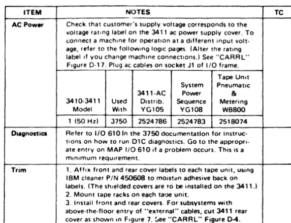
ITEM NOTES TC ITEM NOTES TC Pfec:ement of 1. Install stab,lizer "L" hrackets See F,gure 2. AC Power Check that customer's supply lIoltage corresponds to the
Units 2. Lower rear stabilIzer "L" brackeTs untd they juSt Touch lIoltage rating label on the 3411 ac power supply cover. To the floor and then tIghten the mOunting screws <.:onnect a machine for operatIon at a different input \/olt-3. Mount the SIde COllers loosely, In proper confIguratIon. age, refer to the fOllOwtng logIC pages. (Alter the rating See "SIde Covers" In this chart. label If you change machine connectIons.) See "CARRL" 4. POSItion unIts accordIng to customer reqUtremenTS. FIgure 0·17. Plug ac cables on socket Jl of 110 frame. Note: Due to the length of the 3410 cables, not more
than three 34 lOs can be Installed on eIther Side of the 34 I 1, 5. Af~er machines are In place. snug front stabilizer "L" bracket mountIng supws
6. I nsert large .crewdr Iver through center hole of bracket and pry downward untt! bracket firmly but Just contacts
Tape Unit System Pneumaltc 3411-AC Power &
3410·341 I Used Distrib. Sequence Metering Model W,th YG105 YGlDB WBBOO the floor. Do not raIse casters off the floor· 1 (50 Hz) 3750 25247B6 2524783 2518074 7. FinIsh lIghtening front stabilIzer "L" brackel mounting
screW5.
Note: do not raise transport until all bur stabilizer "L" brackets are ftrmly In place
Diagnostics Refer to 110 610 In the 3750 documentation for Instruc-tions on how to run DIC diagnostics. Go to the approprt· ate entry on MAP 1/0610 if a problem occurs. This is a mtnlmum requlfement,
Shipping 1. Turn vacuum system hold·down bracket approximately Brec:kets 270 degrees clockWise arOl'nd the frame screw. See
alti-tude setting next sectIOn. See also "CARRL" Figure 0·1, Item 28.
2. With front cover off, remove the screws located near each front corner of the transport casting that fasten the transport hold:down brackets to the Side frame. See "CARRL" FIgure 0·1. Item 29. For World Trade only,
Trim 1. Aft,,, front and rear cover labels to each tape unit, using IBM cleaner PIN 450608 to moisten adh~ive back on labels. (The shIelded covers are to be installed on the 3411.1 2. Mount tape racks on each ta'Je unit.
3. Install front and rear covers. For subsystems with above·the-fioor entry of "extf,;rna'" cables, cut 3411 rear Caller as shown In FIgure 7. ~ee "CARRL" Figure 0-4. remOlle only the fight hand screw. The left hand screw
must be left ,n place.
Nota: Do not remolle transport hOld-down brackets from transport castIng. Lealie them In place for reshipment. 3. Remove fIlament tape from the 3411 gate latch. 4. Remove filament Tape from all cables.
Altitude For operation at altItudes ablJlle 3.000 feet (914.4m), move Setting vacuum supply drtve pully so bel t IS dflven by large sheave
of drIve pulley.
See "CARRL" FIgure 0·32, "Vacuum Pump Remollal and Replacement Procedure."
SidaCoHn 1. Open the slIdIng door. CAUTION
To prevent lOP caller damage, always use the Iltting bar to raIse the transport a~sembly. Be sure both support brackets latch. one bracket may requIre manual latchtng. 2. Rals& transport by graiiptng the lilting bar located under the transport and liftIng.
3 Secure the ~Irje callers. (Install SIde cover~ Without oval cutouts at ex~osed ends of subsystem)
3411 Model Vertfy that cards In A I H2, A I J2. and />. I K2 arc plugged Identific:8tion accord,"~ to Tape CClntrolier ALD page Ati001. Power Cabl_ Plug itC power cable (gray} Into ac socket Jl of I/O frame InterfKe Install as shown In FIgure 6. ~oute all power, EPO, and
CabI_ 110 Cables through the culOut In 1 he machIne base Install
cabl~ so that the ends WIth the red labels attach to the
:w 1 1. and the ends WIth the whIte label~ attach 10 1 he 3750 MTA on the 2PA1.
CAUTION
Do not kt.lk these cables.
·CARRL - "Checks, Adjustments, Removals, Replacementii, and LocatIOns" section 01 th;s manual .
[image:11.1232.613.900.81.300.2] [image:11.1232.122.410.81.564.2]•
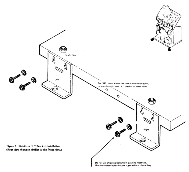
Figure 2. Stabilizer "t" Brack!'t 1i141tallation (Rear view ~hown is similar to I he front view. )
• •
•
•
For 3411 with abovp·the·floor cable Installation,
mount th!' .i~ht r!'ar " L ' hrackeT In thes" hOIf><;
00 not use shipping bolts from packing materials.
•
Use the shorter bolts th?t are ~upplied in a plastic bag.
• •
•
• 'I
[image:12.1230.320.940.89.652.2]VOIt89
.::,1
conneel!)
[image:13.1232.147.744.105.579.2]·Plns Not Present on Mod 3 Logic Board
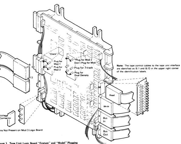
Figure 3. Tape Unit Logic Board "Feature" and "Model" Plugging
Note: The tape control cables to the tape unIt Interlace are IdentIfied as BII and BIO in the upper right corner of the IdentIfication labels.
- ape Unit Logic Board "Feature" and "Model" Plugging
IN STA L 4
;Iexlble Conduit and Ground Strap Installation1. Insert ~onduit between fr;Jmes .
.., Route ground strap through ~()nduit and
secure to mounting s~rews.
3. Using a twisting motion, insert wnduit in
holding damps so the conduit ends extend two or three spirals beyolld ea~h d.lInp.
4. Cable thr~ading is permissIble with wnduit outside machine and may be advisabk in right angle physi~al planning.
•
•
•
• • • • •
Cable Holder
PIN 819410
Figure S. Tape Unit Signal Cable Plugging
•
• •
• •
• • •
•
• If the subsystem has the Additional Tape Unit Feature
(90011, the switching card for Tape Units 4 and 5 is present, and the signal cables for these tape units must
be plugged.
• •
•
•
• • • •
Figure 6. Interface Cable Plugging
•
•
"Terminators not present for System!3 or System/38 or 370/115 and 370/125 ,nstallatlon
•
•
Tape UnIt S,gnal Cable Plugg,ng
I
N STA L 5
Interface Cable Plugging•
•
•
•
•
•
n n
3411 Rear Cover
Cut Cut
1. Using a hacksaw, cut two one-inch slots where indicated. 2. Using adjustable wrench or pliers to grasp cover. bend area
between slots back-and-forth to break out material in <ohaded area. 3. File the edges of the opening to remove sharp edges.
Note: 3411 cover contains metal shielding.
Figure 7. 3411 Cover Modification for Above-the-Fioor Cable Entry
• • • • • • • • • •
•
•
• •
CA R R l
Table ofContents
Figure 0-1. General Locations
Figure 0-2. Power On Off Procedures Figure 0-3. Tape Loop Check
Figure 0-4. Front and Rear Cover Removal and Replacement Figure 0-5. Top Cover Removal and Replacement
Figure 0-6. Sliding Door Interlock Switch Assembly Removal, Replacement, and Adjustment
Figure 0-7. Sliding Ooor Removal and Replacement
Figure 0-8. Operator Switch Assembly Removal and Replacement Figure 0-9. Operator Panel Lamp Removal and Replacement Figure 0-10. Usage Meter Removal and Replacement
Figure 0-11. Usage Meter Card Removal and Replacement
Figure 0-12. Usage Meter Enable/Disable Switch Removal and Replacement Figure .0-13. Usage Meter Transformer Removal and Replacement
Figure 0-14. Usage Meter Circuit Fuse Removal and Replacement Figure 0-15. File Protect Switch Assembly Removal and Replacement Figure D-16. Logic Board Removal and Replacement
Figur. D-17. Terminal Board and Fuse Locations
Figure D-18. Deskew Board Removal and Replacement
Figure D-19. Motion Control Boa~d Removal and Replacement
Figure D-2O. Motion Control Board Relays Removal and Replacement Figure D-21. Motion Control Board Fuses Removal and Replacement Figure D-22. Capacitive Sense Assembly Removal and Replacement
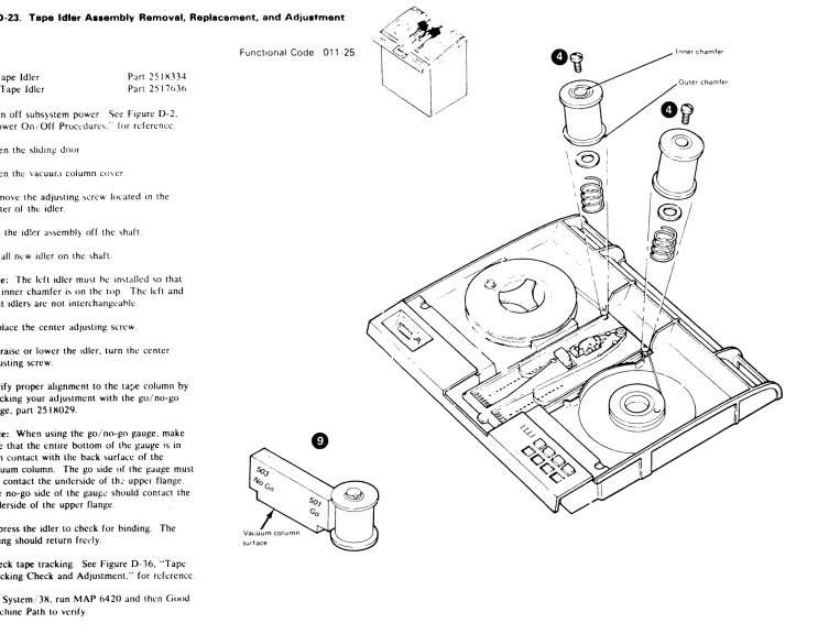
Figure D-23. Tape Idler Assemblies Removal. lIeplacement. and Adjustment Figure 0-24. Tape Guide Assembly Removal and Replacement
Figure 0-24A. Subplate and Guide Adjustment
Figure D-25. BOT
I
EOT Assembly Removal. Replacement. and Adjustment•
• • • •
•
•
•
•
•
•
•
• •
•
•
•
•
•
Figure D-26. Tape-In-Column Vacuum Switch Assembly Removal and Replacement Figure 0-27. Vacuum Check Procedures
Figure 0-28. Vacuum Column Cover Removal and Replacement Figure 0-28A. Tape Load Check and Adjustment
Figure 0-288. Vacuum Column Removal and Replacement
Figure 0-29. Vacuum Column Guide Pin Removal and Replacement Figure 0-30. Vacuum-Up Switch Assembly Removal and Replacement Figure 0-31. Vacuum Pump Removal and Replacement
Figure 0-32. Vacuum System Drive Belt Removal, Replacement, and Adjustment Figure 0-33. Vacuum Motor Assembly Removal and Replacement
Figure 0-34. Vacuum Motor Relay Removal and Replacement Figure 0-35. Capstan Motor Assembly Removal and Replacement Figure 0-36. Tape Tracking Check and Adjustment
Figure 0-37. Reel Latch Assembly Removal and Replacement Figure 0-38. Reel Motor Removal and Replacement
Figure 0-39. Reel Hub Alignment
Figure 0-43. Read/Write Head and Card Assembly Removal and Replacement
Figure 0-40A. Read/Write Head and Card Assembly Removal and Replacement-(Early Modal) Figure 0-41. 3411 Exhaust Fan Assembly Removal and Replacement
Figure 0-42. Tape Control Cooling Fan Assemblies Removal and Replacement Figure 0-43. DC Power Supply Cooling Fan Assemblies Removal and Replacement Figure 0-44. CB1 Circuit Breaker Removal and Replacement
Figure 0-45. CP1, CP2. and CP3 Circuit Protectors Removal and Replacement Figure 0-46. 24-Volt AC Sequencing Assembly Removal md Replacement Figure 0-47. 4-Volt Assembly Removal and Replacement
Figure 0-48. 5- and 6-Volt Assembly Removal and Replacement
Figure D-49. Main Transformer Removal and Replacement
Figure D-50. Power Supply A6K1 and A6K2 Relays Removal and Replacement Figure D-51. Power Supply C4 and C5 Capacitors Removal and Replacement Figure 0-52. Power Supply Fuses Removal and Replacement
Figure 0-53. OC Power Supply Regulator Cards Removal~
Replacement, and Adjustment
Figure D-54. AC Box Assembly Removal and Replacement Figure 0-55. AC Ferro Capacitors Removal and Replacement
Table of Contents
CA R R L 2
Figure D-56. J Plug Locations and Numbering
Figure D-57. Mechanical and Electrical Skew Adjustments
Figure D-S7 A. Mechanical and Electrical Skew Adjustm.n~7 Track Figure D-58. Tape Control Board Pin Layout and Card Numbering
•
•
.'
•
•
•
•
•
•
Figure D-1. Ganeral locations
~ot(': For a \()(:cific location of a terminal hoard or ~l f U'\l'. '>ee Figure D- 17 . "Terminal Board and Fuse
Location,>, ..
U'>agc Meter
2. Enable/Disahle Switch
3. Operator Panel
4. Reel Latch
5. BOT (EOT Assembly
n,
Tape Idlers7. Read/Write Head
H. Vacuum Column Cover
9, Vacuum Pump
10. Vacuum Motor
II. A2 Board
12. A3 Board
13. AC Ferro Capacitors
14. Main Transformer
15. Lifting Bar
16. Reel Motors
17. Read/Write Head and Card Assembly
IX. Capstan Motor
19. Control Unit Cooling Fans
20. Control Unit Gate
21. AC Box 22. DC Box
• •
•
•
•
•
.
'.
'.'
• •
•
•
•
• •
•
•
• •
•
•
:~ DC Vqllat!l' RC1!ulator Can .. ].,
2~. A.S Roard
:::; LO),!ic Board 26. Deskew Board
27. \-tot ion Control Board
:g Pileumatic S1l1pplJ1g Bracket
2Q. Tr:lnsj:'ort Hold Down Bracket
1734556 ~ Sept 72 _ 5 Dec 72 1134132
CAR R L 0-1
CARRL 0-1.5
•
Figure 0-2. Power On / Off Procedure.
SYltem/3, 370/115, and 370/125 Power On/Off
Machines attached to System/3, 370/11 S, and 3701125 can only be p0wered on and off through the system. See the • system operating instructions.
System/38
Machine,> attached to System 3~ arc rowered on and off under "ystem control The Good Machine Path MAP will power up the suh-"y'>tem whilt.: running. power down i'> a CE option.
System/360 and System/370 Power On/Off
Nole: This don not apply to Syslemi J MT A. J 70/11).
or 370/12'5.
Normal power on, off <;t:quencing for the tape control and tape unit'> i ... controlled by "'y<;tem power int~:rlock
circuits. Maintenance activitie ... may neec ... "ilJte droPPing puwer 10 the tape control. BCCJU'>l' \()ltJl-!c . tran<;ients. cau ... ed b) dropping or hringing ur lJre
control power during system opcrJtipn. (',111 GIU"C
erroncou,> sy'>tem interrupts. u'>e the f(\lIowing procedures when dropping or bringing up tape control power.
Power Off:
Note: The channel to which the tape control i<.; attached must complete all operations and ha\ c no pending interrupts before you turn off the tape control power.
1. Vary the subsystem offline. See System/360 and System/370 operating instructions.
2. Set the I NABLE/DISABLE switch to DISARL E.
3.
4.
5.
This allows the subsystem to go offline when the CPU reaches "wail Slale."
Note: An optional way to force the CPU into a
"halt" uf "wail state" is to press STOP at the CPU.
Using your probe box, probe M2P07 on 0 I A. Wait until you get a plus hefore going to Step 4. Set the LOCAL/REMOTI:' switch to LUl AL. Tum power off at the ac box.
J1
"AIA.lpOUI AlIA
T . . . . UIIICE n . - l M'
o
CSl CP3 CP2 CP1~@@
.5 A 12 A 15 A
LOCAL
~~~
POWE R POWER REMOTE ON OFF
':"~' .~~' ,~'.:~.h~. tl~,~:.~t~l~'lh~" ... .
Z p·"t .. I" II. 1\ I \'7Pfl1 I,l' .1" .of' '. ",,1.,1'''1'' .. <,,,,,,' ,,"I PN Rl/'l"
J l,>( ,I' "''',n.,,' 'Iv I, h I, t,II.,'
,q n.·" ... '. 'h. .It ... ' , "
Po¥fef On AttolChed to Sy<t.tem ':>
, £"''',1, d·~.lfll • . ,' ,. ~ 'f, "'\<1"" ~..,
; ~);~'.',:~. ,',I.:',.,',":::';, ::':,~\~'::,:',., ~ ~
4 r ",,1,10 'I'~.II.:, ,,' ·1. II I. ",1,1, i ~
CAUTION
-TUIN MAIN LINE SWITCH OfF tEFORE HANDLING
Funs 01 CONNECTOas
J2
THII VIII,T fcu'''fD ... TM 1..''''''( '11.. 'fill
CIIIICU'''''S SEE IIIIt5T.t..L. .. TtO ... l. ... I .. G -.tA"'lIAl. 11'0" sPICIAl. GlIIOll ... Q1 ... c"liIIrt"( fIII(OVlflll(M('IIT5
J7
J3 J4
THIS MACHINE IS WIRED F"OR )fJ! V.
A6
J5
o
J6
Note: For System/360, System/370 and System
I
370 Models 11-5 and 125 MPX attached only. Does
not apply to System/3 MTA or System/370 Models
liS and 125 that are not MPX attached.
•
Power On:
I. Sct the !·NARLf-/IJIS.\HLI switch to DIS.\HLI .
2. Turn power on at the ae Oox.
3. Sct the LOCAL/RIMOTf switch to RIMO II.
4. Set the !·NARLF/DISABLF- switch to !N.\HU.
This allows the subsystem to go online whl'n the
CPU reaches "wait state."
Note: An optional way to force the CPl' into a
"halt" or "wait state" is to press \TOP :.It the CPU.
Power Off-Attached to System
1 Enable/disable switch to disable 2 Probe pin A·A 1 M2P07 for an up level
(red lamp) using tool PN817971 3 Local/remote switch to local 4 Depress the power off switch
Power On-Attached to System
1 Enable/disable switch to disable
~ Depress the power on switch 3 Local/remote switch to remote 4 Enable/disable switch to enable
Power On 10ff Procedures
CARRL 0-2
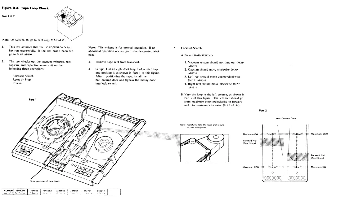
Figure D-3. Tape Loop Check
Page 1 of 2
Note: On System/3R, go to hard copy MAP 6450.
I.
2.
This test assumes that the LOAD/UNLOAD test
has run ~uccessfully. If the test hasn't been run,
go to MAP ABIOO.
This test checks out the vacuum switches. reel. capstan, and capactive sense unit on the following three operations:
Forward Search Reset or Stop Rewind
•
•
•
Note: This writeup is for normal operation. If an
abnormal operation occurs, go to the designated MAP
page.
3.
4.
Remove tape reel from transport.
Setup: Cut an eight-foot length of scratch tape and position it as shown in Part I of this figure. After positioning the tape. install the
half-column door and oypass the sliding door interlock switch.
s.
...
Forward Search:
A. Pn:ss LOAD/RFWIND:
I. Vacuum system sheuld not time out (MAP
.\R I~:!).
2. Capstan should mow clockwise (MAP
.\RI~~).
3. Left reel should move counterclockwise
(MAP AR U~).
4. Right rl'e! should move clockwise (MAP
.\RI)~).
B. Vary the loop in the left column, as shown in
Part 2 of this figure. The left recl should go from maximum counterclockwise to forward
null. to maximum clockwise (MAP ARI3.t).
Note: Carefully fold the tape and secure It over the gUides.
Maximum CW
Forward Null (Reel Stops)
MaXimum CCW
Part 2
Tape t.oop Check
CA R R L 0-3
Page 1 of 2
Half Column Door
o o
8 o
o
o o
c
o
o
o o o
''>-'"''8/J;/'''
o
Ms)omum CCW
Forward Null (Reel Stops)
t
MaXimum CWi
o
I(oooooollJ
I I:nnonn rln!
~.~I.JU)
• •
• •
• • •
•
••
•
•
Figure D·3. Tape Loop Check
Page 2 of 2
6. Stop or Reset Null Condition:
A. Press RESET. The capstan motor stops.
B. Vary the loop in the left column as shown in Part 3 of this figure. The left reel should go from maximum counterclockwise to stop null.
to maximum clockwise (MAP ABL'Io.l).
C Vary the loop in the right column. as shown in Part 3 of this figure. The right reel should go from maximum clockwise. to stop null. to
maximum counterclockwise (MAP ABL'I4).
Part 3
Maximum CW
Stop Null (Reel stops)
MaximumCCW
o
o
000000
MaximumCCW
Stop Null (Reel stops)
MaximumCW
•
•
7
•
•
• •
• •
Rewind Operation:
,\. Press LOAD/REWIND:
I. Capstan turns counterclockwise at rewind
speed (MAP AB136).
2 Left reel turns counterclockwise at high "peed (MAP AB136).
" Right reel turns counterclockwise or
doesn't tum (MAP ABI36).
tL Vary the loop in the left column, as shown in
Part 4 of this figure. The left reel speed should go from maximum counterclockwise to
minimum counterclockwise or stopped (MAP
AS 136).
C. Vary the loop in the right column as shown in Part 4 of this figure. The right reel speed should go from maximum counterclockwise to
stopped (MAP ABI36).
• • •
• •
• •
• • •
•
•
A. P<·~ili'ln each h)(,p ;r :ht stop null position as shl'wI! il) Part 3 \.i 'hi .. figure.
B. Press R'<.;J-T B{lth r:l'I<; <;hou!d SLOP
imme<1:atcly (M-\P 'IP;.IO)
C Pre'iS UNUiAD.'RF\\ l'~[)
D. Prt!SS R FS[ T
E. The vacuum motor and reels should SlOp
(MAP AB!KO). End of tape loop check.
'art 4
Minimum CW or 0
Maximun· CCVI
Tape Loop Check
); Minimum CW or 0
y, Maximum CCW
CARRL 0-3
Page 2 of 2
•
•
•
Figure D-4. Front and Rear Cover Removal and Replacement
Functional Code 000-31
Note: See the IBM 3410/3411 Illustrated Parts
Catalog. order number S132-0006. for pan numbers.
Procedure A - US Only
1. Grasp the cover sides near the top and lift. to
unhook the retaining connectors. then pull outward.
2. Lift the cover to unhook the bottom tabs.
Note: Some machines may have magnetic latches on bottom of cover.
3. Assemble in reverse order.
Procedure B - World Trade Only
The front and rear covers on World Trade machines must be unlatched before removing the cover. The cover is latched at the top left and top right corners.
I . Slide a screwdriver or flat tool along the top edge of the cover until the latch arms in top left and top right corners are unhooked.
2. Grasp the cover sides near the top and lift. to unhook the retaining connectors, and then pull outward.
Note: If the machines are installed close together, it may be necessary to raise the transport assembly to unlatch the rear cover.
3. Lift the cover to unhook the bottom tabs.
4. Assemble in the reverse order. Be sure the
cover is latched when it is in place .
The 3411 Front and Rear Covers _ _ ~.~.
are shielded and have louvers.
•
• •
• •
• •
• • • •
•
Figure
D·5.
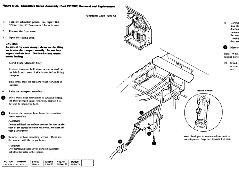
Top Cov ... (Part 2517718) Removal and ReplacementFunctIonal Code 000-31 1. Tum off subsystem power. See Figure D-2,
"Power On/Orr Procedures," for reference.
2. Remove the front cover.
3. Open the sliding door.
4.
CAUTION
To prevent top cover damage, always use the lifting
bar to raise the transport assembly. Be sure both
support brackets latch. One bracket may require
manual latching.
World Trade Machines Only.
Remove transport hold down screw located on the left front comer of side frame before lifting transport.
This screw must be replaced when servicing is finished.
Raise the transport assembly.
Remove the four horizontal screws located under the front of the top cover.
Remove the two screws. one on each side. that secure the cover brackets to the frame. The brackets are located towards the rear on each side.
7. Lower the transport assembly carefully to prevent damage.
8. Close the sliding door.
9. Holding the top cover at the rear, lift up and forward to remove the cover.
Note: When assembling the top cover, make sure the sliding door opens and closes without binding.
10. Assemble in reverse order.
• •
•
• •
• • • • •
• •
• • •
• •
•
•
• •
•
Figure 0-6. Sliding Door Interlock Switch (Part 526088) Removal, Replacement, and Adjustment
l. Turn off subsystem power. See Figure D-2, "Power On/Off Procedures." for reference. 2. Remove the top cover.
Note: The top cover must be removed carefully. Please review Figure D-5, "Top Cover Removal and Replacement." before beginning.
Remove the two switch mounting screws, and then remove the switch from the machine. 4. Remove the two wires from the switch and
transfer them, one for one, to the new switch. 5. Attach the new switch to the machine.
Functional Code 000-34
Sliding Door Interlock Switch AssemblV Removal. Replacement and Ad,ustment
CA R R L 0-6
6. Adjust the switch as follows:
A. Position the switch so that the back screw is
down in the slot.
B. Tighten the screw enough to hold position while adjusting the switch.
C. Replac~ and guide the sliding door as if the top cover was mounted.
D. Move the switch actuator arm up until the switch transfers with sufficient overtravel to meet the the following conditions:
1. The actuating arm doesn't scrape against the sliding door when the door is closed. 2. The actuating arm doesn't slide off the
sliding door when the door is closed. 3. When the switch is manually bypassed. the
closing of the sliding door must reset the switch.
Note: To manuan, bypass the interlock switch. remove the front cover and raise the transport assembly. Reach up through the machine casting and
push the interlock detent plunger to the right.
•
•
•
•
•
•
•
• •
•
•
•
•
Figure 0-7. Sliding Door (Part 2517665)" R&moval and Replacement
I. Turn off 'Iuh'y,ll'm power. See Figun: D-2
"Power On Off Procedures," for referen-:f.. Note: The top cover must be removed carefull~ .. Please review Figure D-5, "Top Cover Renvwal c:-'L~ Replacement, ,. before beginning.
2. Remove the top cover. 3. Remove the rear cover.
4. Unhook the sliding door retaining strap tror . rear support bar.
e
Lift the sliding door out of its track. 6. Place the new door in the track.7. Make sure the sliding door opens and CJOSe~ without binding.
Functional Code 000-32
R. Check the adjustment of the sliding door interlock switch. See Figure D-6, "Sliding Door Interlock Switch Assembly Removal,
Replacement. and Adjustment," for reference. 9. Replace the top cover.
·Order substitute part number 2517910 if the transport has white plastic sliding door guides.
•
•
•
• •
•
• •
•
•
•
• • •
•
• •
•
•
•
•
r---
SlIdIng door guidesFigura 0-8. Operator Switch Assembly (Part 2517620) Removal and Replacement
Note: The entire assembly must be replaced if any individual switch needs replacement.
I. Turn off subsystem power. Sec Figure D-2, uPower On/Off Procedures," for reference.
2.
Remove the top cover.Note: The top cover must be removed carefully. Please review Figure D-5, "Top Cover Removal and Replacement." before beginning.
e
e
Remove and transfer the wires. one for one, to the new switch assembly.
Remove the two screws that hold the assembly in place. The assembly can now be removed from the machine.
Transfer the operator push buttons to the new assemhly.
6. Assemble in reverse order.
( 734556
1 Sept 72
734864
, Aug 73
•
Functional Code 006-11
\
\\
Operator Switch Assembly Removal and Replacement
CARRL D-8
\
\
•
•
•
•
• •
• •
•
•
•
•
•
Figure 0-9. Operator Panel lamp (Part 2518063) Removal and Replacement
Note: If you have a piece of tubing that you
normally use to replace bad lamps. remove the plastic lamp cover to gain access to the lamps. If you don't have this piece of tubing. follow thi" procedure:
I. Turn off subsystem power. See Figure D-2. "Power On/Off Procedures." for reference. 2. Remove the front cover.
3. Open the sliding door.
4 .
CAUTION
To prevent top cover damage, always use the lifting
bar to raise the transport assembly. Be sure both support brackets latch. One bracket may require manual latching.
World Trade Machines Only.
Remove transport hold down screw located on the left front corner of side frame before lifting transport.
This screw must be replaced when servicing is finished.
Raise the transport assembly.
•
Squeeze the springs on each side of the lamp socket. Then pull the socket down and out of the machine.6. Remove the bad lamp. and install a new one.
7. Assemble in reverse order.
Functional Code 006-10
•
•
• • • • •
•
• • •
•
•
•
•
•
•
•
•
•
•
Figure 0-10. Usage Meter Removal and Replacement
60 Hz 50 Hz
Part 740503 Part 740608
Functional Code 770-07
I. Turn off subsystem power. See Figure D-2, "Power On/Off Procedures," for reference. 2. Remove the front cover.
3. Open the sliding door. CAUTION
To prevent top cover damage, always use the lifting bar to raise the transport assembly. Be sure both support brackets latch. One bracket may require manual latchin~.
World Trade Machines Only.
Remove transport hold down screw located on the left front corner of side frame before lifting transport.
This screw mu~t be replaced when servicing is finished.
4. Raise the transport assembly.
• Remove the heat-shrink material from the two meter wires.
•
•
H. Unsolder the two meter wires. Remove the two meter mounting screws. Pull the meter down and out of the machine. Install the new meter in reverse order.Note: Be sure to install new heat-shrink material on the two meter wires .
• 1.l.,.,.).,.I •
•
Usage Meter Removal and Replacement
CA R R L 0 -1
0
• •
• •
•
• • • • • • • • •
Figure 0-". U1tPge MetAr eMf"' 1D:trt :t~l Romova' Bnd R"placement
I. Turn off subsystem power See Figure D-2. "Power On/Off Procedures." for reference.
2. Remove the front cover.
'\ Open the <;lidin/Z door
CAUTION
To prevent top cover damage, always use the lifting bar to raise the transport assembly. Be sure both support brackets latch. One bracket may require manual latching.
World Trade Machines Only.
Remove transport hold down screw located on the kft front comer of side frame before lifting transport.
This screw must be replaced when servicing is finished.
" Raise the transport assembly.
e
Rreak and remove the tamper-proof plugs. Note: 341 0 machlll':;~ !:!.?::ufactured after E(' 44~76Q do not have tamper.proof plugs.Disconnect and transfer the wires. one by one. to the new card.
Remove the two card mounting screws. then remove the card from the machine.
R. Position the new card in the machine. and replace the two card mounting screws.
Ncte: It is not necessary to replace tamper-proof plugs or
Functional Code 770-03
shield on 34 lOs when the card is replaced. The .. meld is required on all 341 1 machines.
SeeEC
History 734864 /44375
1 443800
I
' Aug 73 20 Sept 7" 31 Oct 75
• • • •
• •
• • • • • • •
•
•
•
• •
• •
•
•
Figure 0--12. Usage Motor Enable/Oissble Switch (Part 725347) Removal and Replacement
1. Tum off subsystem power. See Figure 0.2.
"Power OIl/Off Procedurcs." for refereDCe.
2. Remo\'e
me
front COYCl'.3. Open the
sIidiD&
door.CAUTION
To prevent top cover damage, always use the lifting bar to raise the transport assembly. Be sure both support brackets latch. One bracket may require manual latching.
Worid Trade Machines Only.
Remove traDspOI't bold down screw located on
the kft froot comer of side frame before lifting transpOrt.
This screw must be replaced when servicin$ is
fmisbed.
4. Raise the transport assembly.
e
Remove the switch bracket from the meter brack.et. 6. Remove the wires ~onne~ted to the switch.fa
Remove SWitch from SWItch bracket. 8. Install new SWItch In reverse order.Seeec
HIStory
Functional Code n~ 11
•
CARRL 0-12
•
•
•
•
• •
• •
•
• •
•
Figure D-13. Usage Meter Transformer Removal and Replacement60 Hz 50 Hz
Part 740560 Part 740562
Functional Code 770-xx
Note: The 34] ] doesn't have a usage meter transformer.
]. TUl'n off subsystem power. See Figure 0-2.
"Power On/Off Procedures," for reference. 2. Open the sliding door.
3. Remove the front cover.
4.
•
CAUTION
To prevent top cover damage, always use the lifting
bar to raise the transport assembly. Be sure both support brackets latch. One bracket may require manual latching.
World Trade Machines Only.
Remove transport hold down screw located on the ~eft front corner of side frame before lifting transport.
This screw must be replaced when servicing is finished.
Raise the transport assembly.
LDosen the screws that secure the terminal shield, then remove the shield.
•
Disconnect and label the wiring to the transformer.•
8.
Remove the transformer mounting screws, then remove the transformer from the machine. Install the new transformer in reverse order.
• • • • • • • • •
•
•
• • • • • • • • •
•
Figure 0-14. Usage Meter Circuit Fuse (Part 78998) Removal and Replacement
I. Turn off subsystem power. See Figure D-2, "Power On/Off Procedures."
e
Replace the fuse with part 78998.Functional Code 770-18
•
•
•
• • • • • •
•
• • • • •
Figure D-15. File Protect Switch Aaaembly (Part 251n15) Removal and Replacement
I. Turn off suh"ystt:m power. See Figure D-2.
"Power On/Off Procedure,," for reference.
2. Open the "Iiding door.
8
Remove the filler ring.Note: The filler ring is held in place by
adhesive. In<;ert a thin object under the ring and carefu/~v pry it loose. The filler ring is reusable if it isn't bent or broken during removal. If you
FunctIonal Code 005-37
•
need a new filler ring. order PIN 2S 17769. If
e
double backed tape is not reusable. pnsition filler
4.
5.
et
7.
G
ring with rubber cement PIN 450521.
Remove the front cover.
CAUTION
To preyent top cover damage. always use the lifting
bar to raise the transport assembly. Be sure both support brackets latch. One bracket may require manual latchi~.
World Trade Machines Only.
Remove transport hold down screw located on the left front corner of side frame before lifting transport.
This screw must be replaced when servicing is
finished. •
Raise the transport assembly.
Unplug the two cables that go to the switch.
Remove the two mounting screws.
Remove the vacuum hose from the file protect assembly.
10. Install the new assembly in reverse order.
I
See ECHIstory
o
•
• • •
•
• •
\
\
• • • • • • • • •
•
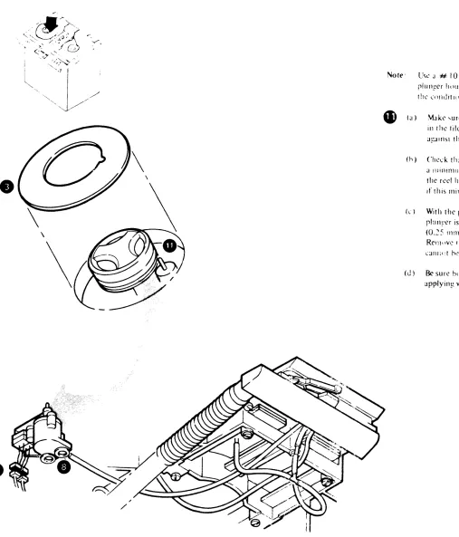
Note' Usc J # 10 wJ,hcr. 11 r('qulf(,U. hctwL'1'1l till'
rlulli!t?r hnU\IIlt! JIlU the Illu((lr pbll' to IIllTI
1!1\.' l'(llldltlllll\ \tJtl'U in II (h) anu Cl').
_ (J) Make "tJrl' tll:!1 tilt? fill' prnlt?c1 plunger filS
ill th\.' tile protect ~ro~)Yl' without funhlllg
J!!:!lnSI the ta~ recl.
(h) Check tilJ1 the file prute~t rlull~(.·r extends a l1lillll1lllJllllf.l ~5 illchc<; (3.17 mm)aoove the reel huh ibl1~c. Insert Ihe # 10 washer if tIllS minll11um cannot be met.
( ... ) With the plun~er retral.'teu. l'hl'ck IIIJI tile plullyer is a Illlllll11Um of .010 itll'h('s
(0.~5 111111) below tht? rcel huh IlJl1?e. Rel1lllvc fhe # 10 washer if this rlllnilllUnl
CHIl;(:1 h,> met.
(J) Be sure botll mi..:ro ~witchcs transfer
ncrore
applyin~ V;JCUIIllLFigure 0-16. Logic Board Removal and Replacement
\1!lLkls I and ~ MOlkl 3
Functional Code xxx-02
8529050 or 8529060 or 8529(170 or 8529080 8529051 or 8529061 or 8529071 or 8529081
1. Turn off subsystem power. See Figure D-2, "Power On/Off Pr0cedurcs," for reference.
2. Remove the front cover. 3. Open the sliding door.
4.
e
G
CAUTION
To prevent top cover damage. always use the liftin2 bar to raise the transport assembly. Be sure both support brackets latch. One bracket may require manual latching.
World Trade Machinc, Only.
RCI110"l' transport hold down sneW IOl'ated Oil till' Idt rront COrtll:r 01 ,ide Irallle hefore lilt in),! lran'porl.
This screw must hl' replal'cd whl'll "'l'n il'in),! i, finishl'd.
RCIllO\ l' till' ,ix \o\ta),!l' l'Ol1l1el'tor ...
Unplug and Iahcl thl' ,ix logic hoard clhk, and till' two jllmpl'r l'anl, ... 0 till'), can hl' plll~~l'd
into till' .... aml' sockets Oil thl' nl'\\ h()~lrd. Tran ... r..:r thl' two jllllllK'r c~m.l ... (PIN 5861451) to
the new board.
8
R~:1l10\l'
tIll' top two l1lollntin),! ... erc\\'"o
l.oo ... en the hottol11 two Ill()Llntin~ ... Ul'W .... 10. Identity the jumpl'f'" that ddinl' 1ll!)dl'l dl1drealml", ~lIld tr~ln ... ll'I lhl'll1 t() th .. : 11l'\\ hn;lrd
II. In,Lili till' Ill'\\ hoard in Il'\""'"' I)nkr,
•
Voltage Connector
Jumper Card (PiN 5861451)
LJ
"-T
'r I ,
/
v~
'Pln~ Not Present on Mod 3 LogiC Board "-~
' / ,". : (
/ L
.l..- ( ~
;"
LogiC BOilrd Removal and Replacement
CARRL 0-16
Socket
Socket Pin Numbers logic Converts To Designatio,.,
A 002 thru 013 I A02 thru A 13 B02 thru B13 A22 thru A33 8 002 thru 013 B02 thru B13 802 thru 813 B22 thru B33 C 002 thru 013 C02 thru C13 802 thru 813 C22 thru C33 F 002 thru 013 F02 thru F13 802 thru 813 F22 thru F33
- , '
J 013 thru 002 J13 thru J02 813 thru 802 J33 thru J22 K 013 thru 002 K13 thru K02 813 thru 802 K33 thru K22 L 013 thru 002 L 13 thru L02 813 thru 802 L33 thru L22 M 013 thru 002 M;3 thru M02
B13 thru 802 M33 thrt.- M22
B13
' /
[image:35.1224.335.1151.80.699.2]•
'•
• •
Fagure 0-17. Terminal Board and Fuse locations
Terminal
Location
!~~rd Name I
--ACTB' i Located inside the AC Box See Figure 0-54
~- ,
---ACTB2 50 Hz only Located inside the AC Box. at the top rear
r
-DCTBl Located on the nght front of the DC Box In the 3411
Located In front of the C4 and C5 capacitors In the :3410 See Figure 0-51
--~---TB2 Located on the 341 1 control unit gate.
f- - ---~--~
T83 Present tn 3410 only. Located on left Side frame See Figure 0-13
-~---T84 Located to the nght of the Read/Wnte Head and Card
;Assem~ly
r l .
-TB5 ! Located in the pneumatic supply See Figure 0-33
A2T81 i Located on the A2 board in the DC 80x. See Figure
10-43
r---- -- ' c
-A3T81 Located on the A3 board in the- DC Bol'.: See F'9ure
0-47_
f---- - -
-1-\ 1T8l Located on the back of the AC Box front cover. System 360/370. See Figure 0-46.
r--- ' - - -
-Usage Meter Located on the usage meter card, Ses Figure D-11.
Card T8
Fuse Name Location
Motion Located on the Motion Control Board. See Figure Control Board 0-21.
Fuses Fl and F2
Usage Meter Located on meter bracket. See Figure 0-14, Circuit Fuse
Fl
A2Fl and Located on the A2 board in the DC Box, See Figure A2F2 0-S2.
A3F1 Located on the A3 board in the DC Box. See Figure 0-S2,
-.
ASFl and Located on the AS board in the DC Box, See Figure A5F2 0-S2.
TB2
A1TB1
••
-•
.'
• •
Motion Control Board Fuses
F1 and F2
•
•
•
• •
•
e
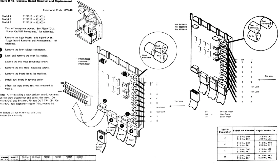
Figure 0-18. Deskew Board Removal and Replacement
Functional Code 009-46
l.
Modell Model 2 Model 3
8529022 or 8529032 8529023 or 8529033 8529024 or 8529034
Turn off subsystem power. See Figure D-2, "Power On/Off Procedures," for reference. 2. Remove the logic board. See Figure D-16,
"Logic Board Removal and Replacement," for reference.
e
Remove the four voltage connectors.e
Label and remove the four flat cables. 5 Loosen the two back mounting screws. 6. Remove the two front mounting screws. 7. Remove the hoard from the machine. X. Install new board in reverse order.'I. Instal! lhl' log,ic hoard that was removed in
Step 2,
802 ~ ... ,~~~,
Note: After installing a new deskew board. you must run the skew dia!%nostics and adjust the '\kew. On Sysh.'m/360 and Systcm/370. run OL T T3410P. On System!3. run diagnostic section 70A. routine 02.
On System; 3~. run MAP h420 and Good Machine PJth to \cnfy.
e
PIN 8529032
PIN 8529033 PIN 8529034
e>eJe;e/e
8 9
DT 5
3 p
2
0
6
4 7T 4
A
C B Not Used Not Used 2 8
4
PIN 8529022 PIN 8529023 PIN 8529024
Top View
Deskew Board Removal and Replacement
CA R R L 0 -18
OT 7T
5 4
7
3 A
P C Top View
•
2 B
Not Used 0 Not Used
6 2
4 8
PT Physical Trade. OT Data Track 1T Seven·Track
Socket Socket Pin Numbers Logic Converts To Designation
013 thru 002 J 13 thru J02 J
813 thru 802 J33 thru J22 013 thru 002 K13 thru K02
K B13 thru B02 K33 thru K22
013 thru 002 L 13 thru L02 L
B13 thru B02 L33 thru L22 Dl 3 t~ru 002 M13 thru M02
M
[image:37.1225.79.1185.88.749.2]•
•
•
•
• •
•
• •
• •
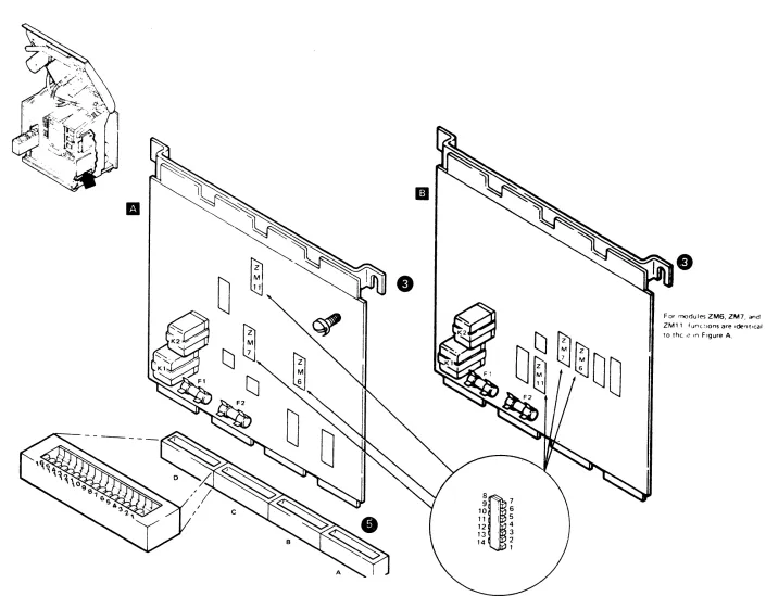
Figure D-19. Motion Control Board Removal and Replacement
Models I and 2
Model ~
Functional Code xxx-05
Part ~7~577 Fl~lIIt' .\. \lr .~73:'S I Fi~lIlc B
Part ~7~57X FigUlt' .\. ;11 3'3~S2 Fll!.lIrl' B
Note: Befprc repl:h:illg J \·l\l:lrJ. chl'ek 1 Ill'
contact ... and sockets on the old hO:1rd to make sure that the)' are clean. If they are dirty. clean them. re\cat thc hoard. and then retr~ the failing operation.
I. Turn off suhsystem power. See Figure D-2,
"Power On/Off Procedures," for reference.
2.
4.
Remove the front cover.
Loosen the front mounting screw nn the motion control board bracket. The rear screw is a shoulder screw and doesn't need loosening. Lift the board straight up to remove it from its socket. It may be necessary to carefully rock the board back and forth to loosen it from the socket.
Insert the new board firmly in the socket. Don't flex the board when applying pressure to seat it.
6. Tighten the bracket mounting screw.
•
•
• •
•
• •
•
•
•
• • •
9 . 7
10
8~
' 6 11 I