mmm
W
COMPUTER CODE FOR TI
IN EVALUATION
ft" V"l"U"'*^ni»l(
»»¿«ij
■mm
Joint Nuclear Research Centre Ispra Establishment Italy
locument was prepared under of the European Communities.
OS
the
m
GAL NOTI
ponsorship of the Commission
ΙΒΙίΐνϋ
Neither the Commission of the European Communities, its contractors nor any person acting on their behalf:
make any warranty or representation, express or implied, with respect to the accuracy, completeness, or usefulness of the information contained in this document, or that the use of any information, apparatus, method or process disclosed in this document may not infringe privately owned
ri§hts:
ΊΒΒΗΒ βΒΕΙΗΗι
assume any liability with respect to the use of, or for damages resulting from the use of any information, apparatus, method or process disclosed in this document.
jtjrtjUÄ ftp 'iiii
This report is on sale at the addresses Usted on cover page
Mm
at the price of B.Fr. 60.—
o m m i s s i o n of the
E u r o p e a n Communities D.G. XIII - C.I.D.
29, rue Aldringen L u x e m b o u r g
IM
This document was reprodi
m
iitiM
ta
EUR 5031 e
R I N A - A COMPUTER CODE FOR T H E RUNNING IN EVALUATION by G. GRAZI ANI and M. PARUCCINI
Commission of the European Communities
Joint Nuclear Research Centre - Ispra Establishment (Italy) Luxembourg, October 1973 - 48 Pages - 8 Figures - B.Fr. 60,—
This report describes a 1-dimensional computer programme, which calculates the approach to equilibrium cycle for thermal reactors, using a partial refueling scheme.
The assumptions made in the calculation method have the effect of strongly reducing the computer time, which, together with the flexibility of the input, makes the use of the code particularly suitable for survey investigations.
EUR 5031 e
R I N A - A COMPUTER CODE FOR T H E RUNNING IN EVALUATION by G. GRAZIANI and M. PARUCCINI
Commission of the European Communities
Joint Nuclear Research Centre - Ispra Establishment (Italy) Luxembourg, October 1973 - 48 Pages - 8 Figures - B.Fr. 60,—
This report describes a l-dimensional computer programme, which calculates the approach to equilibrium cycle for thermal reactors, using a partial refueling scheme.
A B S T R A C T
This report describes a l-dimensional computer programme, which calculates the approach t o equilibrium cycle for thermal reactors, using a partial refueling scheme.
The assumptions made in the calculation method have the effect of strongly reducing the computer time, which, together with the flexibility of the input, makes the use of t h e code particularly suitable for survey investigations.
KEYWORDS
THERMA RECTORS FUEL CYCLE EQUILIBRIUM
R—CODES
E U R S 0 3 1 e
COMMISSION OF THE EUROPEAN COMMUNITIES
R I N A
A COMPUTER CODE FOR THE RUNNING
IN EVALUATION
by
G. GRAZIANI and M. PARUCCINI
1973
3
-1) Introduction
For much of the survey work on reactor fuel cycles, only the equilibrium fuel cycle is usually considered, as it represents the larger part of the reactor life. The contribution of the approach to equilibrium period is usually taken into account,
in the total fuel cycle cost calculation, on the basis of the value of the fuel and fabrication inventorv, which is deduced bv
thé average composition of the equilibrium fuel cycle itself (Ref.1).
This approximation can introduce some errors due not only to the way in which the inventory is calculated, but also to the fact that, in this way, the fuel cycle cost is independent by the strategy followed in the approach to equilibrium phase. These errors can be relatively more important when a comparison is carried out between different types of fuel cycles for a given reactor, where the cost differences result to be relati-vely small.
To avoid these difficulties the 1 dimensional code RINA has been written. In this code the calculation starts with the
initial charge in the core, determining the flux distribution and the nuclear depletion up to the time when the first re-loading occurs. At that time, a fraction of burned fuel is replaced with the fresh one.
The calculation of the flux distribution and the depletion is repeated till the next refueling time. If this procedure is continued long enough, the feed fuel requirements and the com-position of the fuel discharged will not change any more with time and the behaviour of the nuclear parameters will repeat at each cycle. The equilibrium cycle is reached.
In this way the code RINA gives all the informations on the running-in period, as well as on the equilibrium cycle itself. In the following, a detailed description of the programme flow diagramme with the different calculation options is given, together with the description of the methods to solve the burn-up equations, the diffusion equation, the fuel cell self-shielding factors, the multigroup spectrum, and the burnable poison equations.
2) The calculation procedure
The programme flow diagram is shown in fig.1.
- 4
consist in cross section values, fission vields, the fission source spectrum, the convergence criteria and the informations needed to generate the isotopes transmutation chains. Up to 26 energy group and 45 different isotopes can be used.
Next information is that necessary to describe the reactor (case data). The information include the total thermal power of the reactor, the number of diffusion zones (=1 in the case of zero-dimensional calculation) the axial buckling, the height of the core, the radia of the diffusion zones and of the reflec tor, the one group neutron constants for the reflector.
In each of the diffusion zones different burn-up regions can be considered, which have, in general, different volumes and compositions. For a given refueling interval, the programme will search for a single value of the initial fissile concentra
tion in one or more zones, necessary to obtain an imposed reac-tivitv at the end of the interval, or searches for the refueling time when the initial composition is fixed for each nuclide in each region. A third searching option is also included. The code can search both for the concentration and for the refueling time, when the initial and final reactivity values are fixed.
In the first refueling interval, the code allows the possibility of introducing burnable poison. In this case the radius and the initial composition of the burnable poison pin have to be given in the input. The total number of pins is a result of the calcu lation if the poisoned Δ Keff between beginning and end of the first charge is imposed. The possibilitv also exists to give in input the number of burnable poison pins in the whole core. The re-utilization of part of the fissile material discharged can be taken into account, both in the case in which the fissile is immediately available, as when the reactor considered is in an expanding system of similar reactors and in the case in which a certain delay time has to be applied due to the cooling, repro cessing and re-fabrication times. In this last case, the code compares the delay time with the time interval between the two discharges in question, in order to decide if, at that time, the recycling is feasable or not.
The code starts guessing, for example, the initial fissile com position. It calculates, then, the isotope self-shielding
5
-cross-sections with the self-shielding factors previously calculated. The average concentrations obtained with the burn-up routine are used to obtain new zone spectra and the data for the one-group diffusion calculation.
New self-shielding factors are also obtained as function of the average macroscopic obsorption cross-section.
Again the spectra are normalized to the reactor power and a new depletion calculation starts.
Where the difference in average composition reactivities of two successive iterations is below the convergency criterium fixed in the input, the code calculates the initial and the average Kgpp in the refueling interval considered. If the refueling period is the first and if burnable poisons have to be used, the code gives also the poisoned initial and final reactivity, and the number of burnable poison pins. If the final reactivity is different from the imposed value the programme changes consequently the guess of the initial fissile composition and a new external iteration is performed. Where the external convergency is achieved the code discharges
the indicated regions (or a fraction of them) and replaces them with fresh fuel.
A new calculation for the next refueling time then begins.
3) The depletion calculation
The code allows a depletion model in which the transmutation of a nuclide can happen by neutron capture and radioactive decay. Each nuclide may have up to two capture parents and one decay parent.
Fission yields may be specified for each individual fission product resulting from a fission of any heavy nuclide.
Provision is made to take into account leakage out of the system of the volatile nuclides by a leakage constant (see" ). The restriction imposed is that no nuclide can be produced by another nuclide which is in a lower position in the list of isotopes. This implies that, for example, all fission products must follow the fissionable isotopes. All changes in nuclide densities are represented by the system of first order differential equations:
, i . i-1
~ - = - A. . N1 + Sum A. . NJ (i-1, NUCL) (1)
- 6
where NUCL is the total number of burnable elements.
The coefficients Aij of the system equations form a triangu-lar matrix and represent the transmutation rate (by decay or capture) of nuclide j into nuclide i. The diagonal ele-ments Aii are the total removal rate of isotope i out of the system.
The code assumes that all these reaction rates are time in-dependent. In fact they are not, because the flux spectrum varies slightly in the reload interval period. However this variation becomes negligible when the number of reloads in-creases, i.e. when the refueling interval becomes shorter. In order to reduce the large matrix A, the programme, before solving the burn-up equations, investigates the structure of the matrix, separating the independent burn-up chains, i.e. splitting the matrix A in a certain number of small matrices. One of these will be the fission products chain. In order to make the coefficients A¿j to be constant, the fission product
source in the reactor is assumed to be proportional to the average fuel composition of the reactor.
This is equivalent to approximate, in each region of the reac-tor, the refueling scheme to the continuous reload scheme and therefore to assume that the space average concentrations in the zone are equivalent to the time averaged concentrations. This is in most of the cases quite satisfactory.
4) The self-shielding calculation
The space and energy distribution of the flux in the fuel cell of a single zone changes during irradiation, thereby affecting
the effective cross-sections of the isotopes and the neutron balance. For an heterogeneous core, the calculation of the va-riation of the neutron flux spectrum within the cell is of great importance for the calculation of the isotopes burn-up. Therefore a multigroup calculation appears to be necessary. However, in oder to use time constant cross-sections in the depletion equations (1), without neglecting the spectrum va-riation in the fuel element, the code assumes that the flux variation in the cell is function of the time averaged com-position in the cell itself, by means of the self-shielding factors.
7
-reaction rate which would be obtained, if the flux in the cell
was everywhere equal to a reference flux, say the flux at the
cell boundary or the average flux in a given part of the cell.
If the group structure is sufficiently fine, the flux shape
in the fuel element can be supposed to depend only on the macros
copic absorption cross-section of the cell in the energy group
considered.
Few previous transport calculations for the same cell geometry
with different compositions will enable to obtain a fitting of
the self-shielding factors as a function of the cell absorption
cross-section. A good fitting is given for example with the
formula:
SS
IE,i
H E , i
1 + Γ ( τ . + -Σ" . Τ . ) a l Ε V 2 I E , i alE 3 I E , i /
(2)
where
SS
IE,i
is the self-shielding factor of
the isotope i in the energy group
IE
JalE
is the total macroscopic absorpt
ion cross-section of the cell in
the group IE
Τ „ .;T _ .;T„
T„ . are the coefficients supplied into
1IE,l 2IE,l 3IE,l .. ,
/.
DC!.
cthe programme and are different for
each group and isotope.
Two different possibilities of using these self-shielding factors
are envisaged in the programme. The first one assumes that the
average macroscopic absorption cross-section is the average over
the diffusion region, not taking into account the fact that dif
ferent elements with different burn-ups are present in each region.
In the second one, which is more accurate but also more
computer-time consuming, the code considers as many macroscopic absorption
cross-section as the number of burn-up regions in each of the
8
5) The diffusion calculation
A diffusion calculation procedure, not too time consuming but still accurate, is needed, due to the fact that the code has to perform many such calculations in a single run, taking in to account the flux currents and the different flux levels in the various zones in which the reactor is subdivided.
An analytical nodal approach for the solution of the diffusion equation in one energy group is employed. (Ref.2) The basic idea is that the real spatial form of the flux within each region is uninteresting for the code purposes; only the ave rage fluxes in each region are actually needed for the cal culation, while the neutron currents between adjacent regions shall also be correctly evaluated. The one energy group flux is the solution of the second order differential equation:
\7U¿ +
*l
vj/
R= 0
(3)
%
+ BR
"V
with
< -
«V
?fR
rV /
DR
<
4>
The solution of equation (3) with the nodal method leads to the solution of equations of the type
i,
.
A. = ψ . „ X .
+ t . „ Ί .
(5)
vι
1
1+11
1-1 Jι
v'
i being the index of the zone; Α,Χ,Υ being function of the zone characteristics.
The routine starts solving the matrix (5) and calculating the reactivity of the system. If criticality is not achieved, the source term is adjusted and calculation is repeated till the fluxes and the currents match with a critical system.
6) Spectrum calculation and buckling vectors
9
it is a good approximation when the spectrum does not change rapidly within the burnup interval, as it occurs (apart for the first charge) when the core fraction to be reloaded is suffi ciently small.
The flux spectrum in each of the diffusion zone in which the reactor is subdivided must correspond to a critical assembly. For this reason, the spectrum calculation will be repeated, iterating on the buckling values.
The buckling values supplied are the one deduced by the one group diffusion calculation. The direct use of these values to describe the leakages can introduce a distortion into the spectrum, as the energy dependence of the current is not pro perly taken into account by a single value buckling. For this reason, provision is made to introduce into the programme a set of previously calculated buckling vectors V.
With these quantities, the energy group bucklings have to sa tisfy the equality:
S U m DI E BIE ØIB 7 S U m * I E = ÏÏ Ì 2 ( 6 )
IE IE
where
2 —2
BJ E = Β VI E (IE group index)
which imposes that the total leakage has to remain the same. The energy group bucklings obtained from equalities (6) are supplied into the spectrum routine.
The solution of the spectrum matrix equation
c fI E= ( XI E + „ s ™ Γ ^ Ι Ε vf i j } / ( Γ < Μ + s ™ Σ< ι κ +οΙ Εϊ2) (7)
is obtained by iteration.
In the zero dimensional scheme, the possibility of introducing an extra absorber into the core is envisaged in order to match the criticality requirements.
- 10
7) The burnable poison routine
The calculation of the burnable poison depletion equations is based on two main assumptions.
The first is to consider an infinite solid cylinder in a flat flux distribution. The incoming neutrons are monoenergetic and enter uniformly over the entire surface of the absorber, every collision within the cylinder resulting in an absorption.
As a result, an analytical approximated formula for the pin self-shielding factor can be obtained.
The second assumption is to separate the burnable poison pin absorption into a surface contribution and into a volume con-tribution. The surface term has the effect of burning comple-tely a thin layer of thickness dR in the time interval dt, whilst the volume term takes into account the depletion of the burnable poison concentration inside the pin.
A better description of the assumptions and of the calculation method is reported in the Appendix, together with a comparison between the results of the method with those of a more accurate calculation.
For a given geometry and initial densitv °f the burnable poison rods, the programme calculates the number of pins necessary to reduce the reactivity difference between fresh and spent fuel in the first reloading interval to the desired value. In case of more than one diffusion zone, the numbers of pins are taken proportional to the zone volumes (i.e. no power flattening can be obtained with burnable poisons).
The resulting average absorption due to the presence of the absorbers is included in the calculations of the zone spectra.
8) The economic calculation
For practical reasons the economic calculation of the fuel cycle worked out with RINA has not been physically included in the main programme. However the natural way of using the results of RINA is to evaluate them in terms of cost, in order to look at the different influence of the running in period over the total fuel cycle cost and in order to check the validity of the assumption employed in the equilibrium fuel cycles.
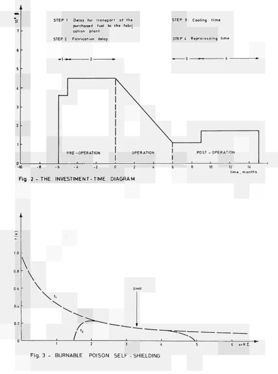
The key to understand the nuclear fuel cycle cost evaluation is the investment-time diagram (figure 2).
In the figure a single refueling interval is reported.
I l
-are represented? by the steps on the left side of the figure. The straight line with negative slope indicates that the reactor is producing energy, and then is producing return money.
The last positive step represents the expenditures due to reprocessing and shipping the spent fuel, and the last step going down to zero indicates that some of the reprocessed material is eventually sold.
In order to actualize all the investments to the same time, the energy was supposed to be produced at the time T-j (at half a way of the refueling interval).
The fuel cycle cost is split into the following items:
fresh fuel consumption: a certain rate of the make-up fuel is introduced into the reactor.
The unit cost of the fresh fuel is given in the input, or it is calculated on the basis of the enrichment, according to the use of ideal Cascade theory (Ref.5). The delay time between the purchase of the fuel and the beginning of the irradiation has also to be given.
Revenue: The spent fuel is eventually sold after reprocessing. The input cost of the spent fuel and the delay time due to cooling and reprocessing have to be given.
Fabrication: on the basis of a fabrication cost per unit fuel weight and of a fabrication delay the contribution to the fuel cycle cost, inversely proportional to the fuel burn-up, can be calculated.
Reprocessing: the same as for the fabrication.
In order to calculate the average total fuel cycle cost, the calculation has to be performed along the total reactor life. All the expenditures and revenues have to be actualized at
the same time at the numerator of the fuel cycle cost formula, as well for all the energy produced (at the denominator).
The difference, between the total fuel cycle cost and the fuel cycle cost for the equilibrium refueling interval, gives the contribution of the running in period to the fuel cycle cost and can be directly compared with the approximate eva-luation resulting from the usual equilibrium economic calcula-tions.
9) Output description and computer time
The list
12
-iteration procedure can be easily followed in the output lisi. At each external iteration, the number of burnable fission
pins, Ke££ initial and final with and without burnable poisons
are printed.
For each refueling interval, when convergence is achieved, the initial and final isotopie compositions are printed, together with zone spectra and neutron balance for each region.
The power fraction of each zone, age factors (*), average region conversion ratios (**) are also given.
Finally a number of data are edited and punched on cards, which may be used if a calculation of the fuel cycle cost has to be performed. These are, for each interval, the weight (grams) of heavy isotopes charged into the core and discharged, the zone power density (w/cc) times the maximum age factor in the zone and the refueling time (days).
Computer time depends very much on the complexity of the problem. It is function of the number of cycles, the number of zones and burnable regions, and depends also on the different options used for the criticality search, for the self-shielding
calcula-tion and for the burnable poison calculacalcula-tion.
As an example, for a case consisting of 12 refueling intervals with 20 energy groups, 45 isotopes and 16 burnable region, in one-dimensional approach, a computer time of about 3 minutes can be expected for the IBM 360/70.
(*) (defined as the ratio between initial and average fissions) (**)(which is the absorptions in fertile materials over
13
Appendix
The burnable poison absorption as a function of the irradiation
A method to calculate the self absorption of monoenergetic neutrons in an infinite cylinder was developed by W.J.C. Bartels (Ref.2). He derives an analytical expression of the selfshielding factor as a function of the parameter
X = R i
R being the cylinder radius
Σ being the macroscopic total crosssection of the cylindrical medium
The approximate solution of the integral derived by Bartels leads to two analytical expressions, one for small and the other for large values of χ
«^ 2n+2
Small χ f„ (x)=177 x + Sum Α χ (ln2V+a in χ) (8)
1 3 η fin
n=o
with a = (2n)!
n 22n(n+2)/ (n+1)! nij2
Large χ f (x) = \ - (1 2 — (1+5 (ι+ 1°Σ- <1 + ) (9)
¿ X 16x¿ 8x¿ 32x¿
The behaviour of these two expressions is reported in figure 2. The figure shows that the two formulae give the same results for χ being the interval (2.5,4). A value of χ in this range must
then be chosen to pass from one expression to the other in the calculation of the selfshielding factor. A break even point of 3.3 has been used in the following.
Employing the expressions (8) and (9), it is possible to calculate with a certain approximation the flux depression in each energy group in the burnable poison pin, and then to calculate the total reaction rate at the initial time.
To study the evolution of the total reaction rate with the irra diation, the following assumptions have been made
The spectrum in the medium surrounding the burnable poison element is kept constant in
time '
The absorption in the pin can be separated into two contributions: a volume and a surface term
If the volume absorption rate is defined as
14
and fj)c is the total flux at the center of the pin
φ is the incoming flux
Ρ is the total self shielding factor averaged over the groups,
we can define the parameter5 as the excess of the absorption rate due to the presence of the surface absorption relative
to the real average absorption rate.
do)
with
yïE
We can now assume that the excess absorption due to the surface term has the result of burning completely a thin layer of thick ness dR in the time interval dt.
The fraction of neutrons which contribute to this radius deple tion will be \ , (1|) being the neutrons which enter the rod burning uniformely the burnable poison inside. In this case the two depletion equations for radius and burnable poison den sity can be written.
'
H
i„RJR= 5 U . Ç ZjnR'it
fu)
¿N
r
-{A-%)^]Nlt
da)
15
b u r n u p (MWd/Kg)
0
4
13
17
(Σ- ¿
c) / a
c^
c)t=o
1
1.035
1.08
1 .22
t o t a l absorption
1
0 . 8 4
0 . 5 9 5
0 . 4 0 6
From the table, it can be deduced that the quantity
N
c[i)
W
^ .
£g
a/fE= ? Λ
is roughly constant. Employing the definition of £ (10) the expression
1 3 = const / φ Tl
is obtained for the dependence of *J on the irradiation. In order to check the validity of our assumptions a certain number of calculations has been carried out using the code MINOTAUR (Ref.4) in which a burnup routine has been added in order to perform the depletion of the burnable isotopes present in the pin.
The cases studied involved different rod radia from 0.07 to 0.28 cm.. The pin composition was chosen to be natural Gado
linium oxide with a density of 7.4 gr/cc. The incoming spectrum was a typical HTR spectrum in 15 energy groups. The mesh parti tion has been chosen sufficiently fine at pin edge, at the be ginning, and has been changed at about half of the irradiation considered.
The initial values of £ for different radii have been calculated with MINOTAUR and are reported in figure 4.
- 16
The comparison of the results of MINOTAUR with the approximate
anlytical method are shown in fig. 5,6,7,8 where the total reaction
rate taking place in the pin is reported versus burn-up for the
different pin radii considered.
The small discrepancy at low irradiation values are due to the approximate calculation of the self-shielding factor. The slope of the curves is, however, almost the same in all the cases and justify the assumption made on the dependence of ^ on the irradiation.
References
1) C.Zanantoni, M.Paruccini - COFFEE-Α code for the assessment of fuel cycle costs - not available
2) C.Rinaldini - A nodal approach to solve few region neutron diffusion problems - Energia Nucleare - Vol.17 N. 7 - July 1970
3) W.J.C.Bartels - Self absorption of mono-energetic neutrons KAPL-336
4) MINOTAUR (Oppenheim): Version BBK (Mannheim) AKI 709-71, 210-1609
- 17
Read library data
Read case data
τ
1s t refueling interval
I
Guesses on flux level ini tial and average densities
yes
1 0
Adjust feed quantity
no
*|Self shielding calculation
Spectrum calculation
Diffusion calculation
ι —
Normalize spectra to reactor power
Depletion calculation, compute av. and final
isotopie densities
I
is this the 1s t iteration?
final Kef£ and burnable
poison calculation
Print, discharge a region, recycle the fissile produced
Next ref. interval calculation
18
-i
•
o 7
6
5
4
3
2
1
n
1
STEP 1 : Delay for transport purchased fuel to I h cation plant STEP 2 : Fabrication delay
* 1 - » ~ i 2
-1 ,
PRE-OPERATION
►
-1
1
1
ι
1
1
I
1
I
1
1
of the e fabri
OPERATION
ι 1
STEP 3:
STEP 4 :
3
1 1
1
Cooling t i m e
Reprocessing time
>~. 4
POST - OPERATION
1 1 1
» ■
1 1 - 1 0 - 8 - 6 - 4 - 2 0 2
Fig. 2 - THE INVESTMENT-TIME DIAGRAM
8 10 12 14 t i m e , months
1.0
0.8
0.6
0.4
0.2
\
\
\
\
/ . < '
limit
^
Fig. 3
1 2 3 4
BURNABLE POISON SELF - SHIELDING
[image:22.595.32.578.70.805.2]- 19
0.5
0.4
0.1 0.2 0.3 Burnable poison pin radius (cm)
Fig. Ü - VARIATION OF THE INITIAL VALUE OF É WITH THE PIN RADIUS
1) from MINOTAUR
2) with the approximate method
20
-R0= O.H cm 1) from MINOTAUR
2) with the approximate method
30 MWd/kg
- 21
R0= 0.21 cm
1) from MINOTAUR
2) with the approximate method
MWd/kg
Fig. 7-BURNABLE POISON REACTION RATE A S A FUNCTION OF THE IRRADIATION
Ro=0.28 cm 1) from MINOTAUR
2) with the approximate method
60 MWd/kg
LIBRARY DATA Word Column Format Card N° A1 Symbo1 1 1-4 Integer Number of energy groups (less or equal 26) N26 2 5-8 Integer Number of fast groups (less or equal 20) N23 3 9-12 Integer Number of cross section blocks (less or equal 45) NLB 4 13-16 Integer Number of heavy nuclides NHEV 5 17-20 Integer Number of moderator nuclides (less or equal 3) NLM 6 21-24 Integer Dummy NLT Word Column Format Card N° AT (cont. ) Symbo1 7 25-28 Integer If larger than 0 prints neu-tron balance and spectrum in each dif-fusion region NCOST 8 29-32 Integer id.number of the control (should be zero if no Xe-override calculation is desired) NBORON 9 33-36 Integer id.number of the Xe-135 in the library NXE5 10 37-40 Integer id.number of the unit from which the code reads the library data NI 11 41-44 Integer the id.
! V/ord ; Column
f ■
i Format
j
i
ι I
! Card
\ N°A2
f
i
! ! ! ¡ Symbol 1 14 Integer Nuclide number L 2 58 Integer Nuclide number of 1st capture parentNCAP1 (L)
3 912 Integer Nuclide number of 2nd capture parent
Ν CAP 2 (L)
4
1316
Integer
Nuclide number of Ν, 2N parent
NN2NN (L)
5 172U Integer Nuclide number of decay parent
NB3TA (L)
6 2124 Integer Nuclide has nonzero βϊ? 0 - No 1 - Yes
KFIS3 (L) Word column ι Format 1 I ! I Card N° A2 (cont.) ; Symbol 7 25-28 Integer Nuclide is a fission product? 0 - No
1 - Yes
KFP (L)
8
29-32 Integer
Nuclide has non-ζ ero
0 - No 1 - Yes
KN2N (L) 9 33-36 Blank 10 37-48 Decimal Decay constant X.LAM (L) 11 49-60 Decimal Leakage constant XLEAK (L) 12 61-72 Decimal Atomic weight AWT (L) Comment
Supply one card for each nuclide
Word Column Format Card N° A3 Symbo1 1 1-4 Integer 1st nuclide is primary fissile? 0 - No 1 - Yes
NFA (1) 2 5-8 Integer 2nd nuclide is primary fissile? 0 - No
1 - Yes
NFA (2) 3 9-12 Integer 3rd nuclide is primary fissile? 0 - No 1 - Yes
NFA (3) 4 13-16 Integer etc. etc. 5 17-20 Comment
Supply one word of data for each heavy nuclide. See card A1 word 4 Continue on additional cards if necessary. to Word Column Format Card N° A4 Symbol 1 1-4 Integer 1st nuclide is prim, fiss. pre-cursor? 0 - No 1 - Yes -1 Neg contrib NCR (1) 2 5-8 Integer 2nd nuclide is prim, fiss. pre-cursor? 0 - No 1 - Yes 1 Neg
Contrib/-NCR (2) 3 9-^2 Integer 3rd nuclide is prim, fiss. pre-cursor? 0 - No 1 - Yes -1 neg contrib
NCR (3) 4 13-16 Integer etc. etc. 5 17-20 Comment
Supply one word of data for each heavy nuclide.
See card A1, word 4.
Word Column Format Card N° A5 Symbo1 1 1-12 Decimal Fiss.Yield from 1st heavy nuclide YIELD(I,1) 2 13-24 Decimal Fiss. Yield from 2nd heavy nuclide YIELD (1,2) 3 25-36 Decimal Fiss.Yield from 3rd heavy nuclide YIELD CX.3) 4 37-48 Decimal etc etc. 5 49-60 Comment
Supply a yield value from each heavy nuclide.See card A1,word 4. Supply a set of yields for each fiss.product. Begin each set on a new card.
See card A2,word 7
Word Column Format Card N° A6 Symbol 1 1-6 Alphanumeric Nuclide Identifica-tion CLOG 2 7-60 Alphanumeric Other cross-block identi-fication CNAME 3 60-64 Integer 0 -Not a
moderator 1-moderator NMOD 4 65-68 Integer Read transfer Tiatrix?
0 - Yes 1 - No
Word
Column
Format
Card
N° A7
Symbol
1
1-12
v<r
fF I S I G
2
1 3 - 2 4
$ t r
TOS IG
3
2 5 - 3 6
<^a
ABS IG
4
3 7 - 4 8
6"
OUSIG
5 4 9 - 6 0
V
XNU
6
6 1 - 7 2
n , 2n
*' XNSIG
Comment
Supply one card for each energy group.
See card A1, wordl.
Word
Column
Format
Card
N° A8
Symbo1
1 1-12 Decimal
^ g , g + i
OUSIG
2
1 3 - 2 4 Decimal
* g , g + 2
3
2 5 - 3 6 Decimal
^ g . g + 3
4 3 7 - 4 8 Decimal
e t c .
5 4 9 - 6 0 Decimal
6
6 1 - 7 2 Decimal
Gg, l a s t f a s t group
Fast group transfer matrix: Start a new
Comment
card for each group.
Word Column Format Card N° A9 Symbol 1 1-12 Decimal
rg, 1 s t
a' thermal
group OUSIGM 2 13-24 Decimal <S" ,2nd
g thermal
group
3 25-36
Decimal
3 thermal
group 4 37-48 Decimal etc. 5 49-60 Decimal 6 61-72 Decimal
& , last thermal group OUSIGM Comment Transfer into thermal region for moderators only:
Start a new card for each group. Supply this data for all fast and thermal groups.
Word
Column Format
Card N° A TO
-Word Column Format
Card N° A11
Symbo1
1 1 1 2
Decimal
Flux
convergence c r i t e r i o n
CONK
2
1 3 2 4
Decimal
Flux loop convergence c r i t e r i o n
EPS1
3 2 5 3 6
Decimal
F i n a l K „„ e f r convergence c r i t e r i o n
EPS 2
4
3 7 4 8
D e c i m a l
F r a c t i o n of power
r e d u c t i o n f o r X e o v e r r . c a l c u l a t i o n
XFRAC
Comment
CM CO
O J ω
V
r— COO. H
V
w S O O
m
O O o
d
O O o ■
τ— o
o o o
φ Η
(tí
X
φ
ÍH
O CM
Word Column F o r m a t
Card
Symbol
to
SELF SHIELDING DATA
Word
Column
Format
Card 1B
Symbol
1
1-4
Integer
Number of self shielding set to be supplied
(if zero skip to card 1)
NSET
to
CO
Word
Column
Format
Card 2B
Symbol
1
1-4
Integer
Set number
I
Word Column Format Card 3B Symbo1 1 1-12 Decimal First coefficient group (1) T1(I,1) 2 13-24 Decimal Second coefficient group(1 ) T2(I,1) 3 25-36 Decimal Third coefficient group(1) T3(I,1) 4 37-48 Decimal First coefficient group (2) T1(I,2) 5 49.-60 Decimal Second coefficient group (2) T2(I,2) 6 61-72 Decimal Third coefficient group (2). T3(I,2) Word Column Format Card 4B Symbol 1 1-4 Integer Id. Number of the self shielding set for isotope 1 ISET(1) 2 5-6 Integer Id. number of the self shielding set for isotope 2 ISET (2) 3 7-8 Integer etc. ISET (3) Comment Continue on another card if necessary. Comment
CASE DATA
Vio r d Column Format
Card N° 1
Symbo1
,
1-72
Alphanumeric
Case
identifica tion
* .—— 1
I CO
Word
Column Format
Card 2
1 Symbol
1
1-4 Integer Number of refueling intervals in the calculation
[less or equal 15)
NCYCLE
2
5-8
Integer Number of total burn-up regions
(less or equal 16)
Ν REG
3
9-12 Integer Number of
initial isotopie densities different from zero
NREAD
4
13-16 Integer Number of refueling
intervals having a complete print-out
NCOS
5
17-20 Integer Maximum number of iterations (usually 100
JNSTOP
6
21-24 Integer Maximum iterations in a single flux loop
Word Column Format Card 2 (cont.' Symbol 7 25-28 Integer Iteration control number (as usually equal to word 5)
JNESTP 8 29-32 Integer Number of diffusion regions NZONE 9 J3-36 Integer Buckling option; if greater than 0 the one-group buckl. will be shared among the groups NVECT 10 37-40 Integer = 1 the number of burnable poison pin is searched. If less than zero NPIN=-NFIXP (1)*100 NFIXP(1) 11 41-44 Integer Number of buckling iterations NFIXP(2) 12 45-48 Integer = 1 the fissile produced is recycled NFIXP(3) CO to Word Column Format Card 2 (cont ; Symbol 13 49-52 Integer 'self-shielding cale.option =0 average s.s.f. per diffusion
zone.
' =1 average s.s.f. per burn-up region NFIXP(4) 14 53-56 Integer Identification number of 1st burnable poison in the library NFIXP(5) 15 57-60 Integer Identification number of the moderator ( if any ) in the burnable poison pin NFIXP(6) 16 61-64 Integer Number of burnable ■ poisons
(less or eaual 4)
I I Vio r d
Column Format Card 3 Symbo1 1 1-4 Integer If less or equal zero, no burnable poison in this zone NFIXP1(1 ) 2 5-8 Integer if less or equal zero no burnable poison in this zone NFIXP1(2) | Word Column Format Card 4 Symbo1 1 1-12 Decimal Moderator density (if any) in the bur-able poison pins zox 2 13-24 Decimal Radius of burnable poison pins RZERO 3 25-36 Decimal Initial density of the 1st burnable poison isotope in the 1st diffusion region BP1(1,1) 4 3 7-48 Decimal BP1 (2,1) 5 H'J-SO Decimal BP1(3,1) 6 61-72 Decimal Initial density of the last burnable poison isoto pe in the
1st diffu sion region
BP1(JPOIS,1)
.omment
unly if JPOIS is larger than u. As many words as Ν ZON 2
co co
Comment
only if JPOIS larger than 0.
continue on an
Word Column Format
Card
5
Symbo1
1
1-4
Integer Pype of seajEh ίη the 1st in terval
= 0 feed search =-1 time
search =+1 feed plus
time search
NTYPS(1)
2
5-8
Integer
Type of search in the 2nd interval
NTYPE(2)
3
7-12
Integer
Type of search in the last refueling interval
JTYPE(i\ CYCLE)
,'omment
oupply as many words as the number of refuel
ing intervals
CO
Word Column Format
Card
6
• Symbol
1 1 - r t Integer If greater than zero the feed search is performed in
this diffu sion region
ÌCHANG(1)
2
5-8
Integer
i. Hi--nG( 2 )
3 7-12 Integer
Word Column Format Card 7 Symbo1 1 1-12 Decimal Number of fission per watt.sec FIWATT 2 13-24 Decimal Total reactor power(w) POWER 3 25-36 Decimal Minimum value for the feed search FMIN 4 37-48 Decimal Maximum value for the feed search FMAX 5 49-60 Decimal Minimum value for the time search TMIN 6 61-72 Decimal Maximum value for the time search TMAX Word Column Format Card 8 Symbol 1 1-12 Decimal Feed (or time] initial
change in the search (if 0 the code puts it equal to 1.5) DELTFD 2 13-24 Decimal Diffusion coefficient of the reflector DI(NZ0NE+1) 3 25-36 Decimal Macroscopic absorption cross-sectio of the reflector SA(NZ0NE+1) 4 37-48 Decimal Core height n HEIGHT 5 49-60 Decimal Cooling plus reprocessing and re-fabrication times (in the recycling cases) TRFUEL 6 61-72 Decimal Maximum quantity of fuel that can be re-cycled in each re-fueling interval
Word
Column
Format
Card
9
Symbol
1 1-12 Decimal
Radius of the first diffusion region(cm)
RZ0NE(1)
2 13-24 Decimal
Radius of the second diffusion region(cm)
RZ0NE(2)
3 25-36 Decimal
Radius of the last diffusion region(cm)
RZONE(NZONE)
4 37-48 Decimal
External radius of the reflecta
(cm)
RZ0NE(NZ0NE+1)
CO Oí
Word
Column Format
Card 10
Symbol
1 1-4
Integer The id.Number of the isoto-pe in which the first heavy metal is recycled (if=0 no
recycling)
NSWIT(1)
2 5-8
Integer
NSWIT(2)
3 9-12
Integer The id.number of the isoto-pe in which
the last heavy metal is recycled (if=0 no
recycling)
NSWIT(NHEV)
Comment
Only if word 12,
card2 is larger
Word Column Format
Card 11
Symbo1
1 1-12
Decimal Fraction of the first
isotope to be recycled
QJR(1)
2 13-24
Decimal
QR(2)
3 25-36
Decimal Fraction of the last isotope to be recycled
0R(3)
Word Column Format
Card 12
I Symbol
1
1-4
Integer If greater than zero the 1st burn-up zone
be-longs to the 1st diffusion region
KZID(1,1)
2
5-8
Integer
KZID(2,1)
3 9-12
Integer If greater than zero, the last burn-up zone belongs to the 1st diffu sion region
KZID(NREG,1)
Comment
Only if word 12, card 2 is larger than 0.
CO -J
Comment
Word
Column
Format
Card
13
Symbol
1
112
D e c i m a l
The f e e d g u e s s i n t h e
1 s t d i f f u s i o n r e g i o n
( 1 s t c y c l e )
FEED(1,1)
2
1 3 2 4
D e c i m a l
FEED(1,2)
3
2 5 3 6
D e c i m a l
The f e e d g u e s s i n t h e l a s t d i f f u s i o n r e g i o n ( 1 s t c y c l e )
FEED(1,ΝΖΟΝΕΙ
Comment
As many cards 13 as the number of the refueling in tervals
Word
Column
Format
Card
14
Symbol
1
112
D e c i m a l
Time o f t h e f i r s t r e f u e l i n g i n t e r v a l
( d a y s ) ( f i x e d o r
g u e s s )
DELDAY(1)
2
1 3 2 4
D e c i m a l
DELDAY(2)
3
2 5 3 6
D e c i m a l
Time o f t h e l a s t r e f u e l i n g i n t e r v a l
( d a y s )
DELDAY(NCYCLÏ )
Comment
As many words as the number of
Word
Column
Format
Card
15
Symbol
1
1-4
Integer Number of t o t a l burn-up regions in the f i r s t r e -fueling in-t e r v a l
NRG ( 1 )
2 5-8
Integer
NRG ( 2 )
3 9 - 1 2
Integer Number of t o t a l burn-up regions
in the l a s t refueling i n t e r v a l
NRG(NCYCLE) CO
CD
Word
Column
Format
Card
16
Symbo1
1
1 - 1 2
Decimal Fraction of the 1st burn-up region to be dischargee at the end of the 1st refueling in-terval
XFRACT(1,1)
2
1 3 - 2 4 Decimal
XFRACT(1,2)
3
2 5 - 3 6
Decimal Fraction of the l a s t burr up region to be dischargee at the end of the l a s t refueling i n t e r v a l
XFRACT(1TNRG)
Comment
Word
Column
Forma.t
Card
17
Symbol ¡
1 1-12
Decimal Final K-eff value
(1st refuel-ing interval
ZKMIN(1)
2 13-24
Decimal
ZKMIN (2)
3 25-36
Decimal Final K-eff value
(last refuel-ing interval)
ZKMIN(NCYCLE)
Comment
As many words as the number of refueling interval Continue on an-other card if necessary.
Word
Column Format
Card
18
Symbol
1 1-12 Decimal Difference between initial and final
reactivity ol 1st refuelinc interval
DK(1)
2 13-24 Decimal
DK(2)
3 25-36 Decimal Difference between initial and final
reactivity of the last refueling interval
DK(NCYCLE)
Comment
AS many words as the numDer of refueliiig
in-tervals.
Í Word ι
Column
Format
Card
19
Symbol
1
112
Decimal
Axial buckl ing of the first energy group and the first diffusion region
TRANS(1,1)
2
1324
Decimal
TRANS(2,1)
3
2536
Decimal
Axial buckling of the last energy group and the first diffusion region
TRANS(N26,1)
Comment
Continue on an other card, if necessary.
As many cards 19 as the number of diffusion regions.
Word
Column
Format
Card
20
I Symbol
1
112
Decimal
Vector for radial buckl
ing first energy group and first diffusion region
VECTOR(1,1)
2 ',■
1324
Decimal
VECTOR(2,1)
3
2536
Decimal
Vector for radial buckl
ing last energy grouj and first diffusion region
VECT0R(N26,1)
Comment
Only if word 9 in card 2, is greater than 0.
Word Column Format
Card 21
Symbol
1
1-4 Integer
Id. number of the isoto-pe in the library
II
2
5-16 Decimal
Feed
fraction in the isotope
Z(II)
Comment
Supply as many cards 21, 22, 23, 24 as indi-cated by word 3 in card 2.
to
Word Column Format
Card 22
Symbol
1 1-12 Decimal
Initial
concentratior of the iso-tope in the 1st burn-up zone of the fresh core
CDEN(II,1)
2
13-24 Decimal
.
CDEN(II,2)
3 25-36 Decimal
Initial
concentratior of the isoto pe in the last burn-up zone of
the fresh core
CDEN(IINREG)
L
Comment
Word
Column
Format
Card
23
Symbol
1 1-12
Decimal
I n i t i a l i s o t o p i e c o n c e n t r â t , t o be r e -f u e l e d a t t h e end of t h e 1 s t char.ge
BDEN(II,1)
2
1 3 - 2 4
Decimal
BDEN(II,2)
3 25-36
Decimal
I n i t i a l i s o t o p i e c o n c e n t r â t . t o be r e -f u e l e d a t t h e end of t h e l a s t char.ge
BDEN(II,NCYCIE)
Comment
As many words as the number of refueling in-tervals
Word
Column Format
Card
24
l Symbol
1
1-12
Decimal
I s o t o p i e d e n s i t y m u l t i p l i e r
i n t h e 1 s t d i f f u s i o n r e g i o n
0 D E N ( I I , 1 )
2
1 3 - 2 4
Decimal
0 D E N ( I I , 2 )
3 2 5 - 3 6
Decimal
I s o t o p i e d e n s i t y m u l t i p l i e r i n t h e l a s t d i f f u s i o n r e g i o n
0DEN(II,NZ0NE )
Comment
As many words t h e number of
a s
d i f f u s i o n r e g i o n s . I f I I i s l e s s NREAD, r e t u r n c a r d 2 1 .
t h a n t o
ECONOMIC DATA
Word Column Format
Card C1
Symbol
1 1-4 integer
if zero, reac new economic data; if greater than 0, employes the previous economic data; if les; than 0, cal-culation stop;
ICHG
Word Column Format
Card
C2
Symbol
1
1-72
alphanumeric a:
Case title
TITLE
This card is the
1s t of each RINA
Word
Column
Format
Card
C3
Symbol
1
1-4 integer
Case number
ICASE
2 5-8 integer
number of the 'refueling intervals
NCYCLE
3 9-12 integer
number of the heavy materials
NHEV
4 13-16
integer
number of cost data
(effective only if ICHG is equal 0)
NCOST
5 17-20 integer
id. number of Uranium 235
NU5
6
21-24 integer
id. number of Uranium
238
NU8
en
Word
Column Format
Card
C3 [cont.)
I Symbol
7 25-28 integer
number of refueling fractions
NREG
8
29-32 integer
number of the refueling
in-tervals be-longing to the Running-I
NEND
9 33-36 integer
number of diffusion zones
1
Word
Column
Format
Card
C4
Symbo1
1 1-4 integer
If larger than 0, the 1st isotope is charged into the core
NFED(1)
2
5-8 integer
NFED(2)
3 9-12 integer If larger than 0, the last isotope is charged into the core
NFED(NHEV)
Word
Column Format
Card
C5
Symbo1
1 1-4 integer If larger than 0, the 1st isotope is discharged from the core
NREC(1)
2 5-8
integer
NREC(2)
3 9-12 integer if larger than 0, the last isotope is dischargee from the core
NREC(NHEV)
Word
Column
Format
Card
C6
Symbo1
1
1-12
d e c i m a l
R e a c t o r t h e r m a l power (w)
POWER
2
13-24 decimal Core volume.
(cm3)
VOLUME
3
25-36 decimal Thermal e f f i c i e n c y
ETA
4
37-48 decimal
Load f a c t o r
HOUR
5
4 9 - 6 0
d e c i m a l
R e a c t o r l i f e ( y )
TL I FE
After this, the cards of the RINA punch have to be
introduced (apart the title card)
-a
Word
Column Format
Card
C7
Symbo1
1
1-12
d e c i m a l
v a l u e of t h e 1 s t h e a v y m e t a l
( t / K g )
V(1)
2
1 3 - 2 4
d e c i m a l
-.
V(2)
3
2 5 - 3 6
d e c i m a l
v a l u e of t h e l a s t h e a v y m e t a l
($Ag)
Vio rd Column Format Card C8 Symbo1 1 1-12 decimal Cost of separative work
($Ag)
SWR K 2 13-24 decimal tail enrichment TAIL 3 25-36 decimal Cost of natural Uranium CU38 4 37-48 decimal Annual interest rate AIR 5 49-60 decimal Additional cost in the Uranium gaseous phase ALFA9 6 61-72 decimal Fabrication dependence on the ini-tial enrich-mentAL FA 8
Word
Column F o r m a t
fe'; l p
Wt&ÉäMfåM
111
.
N O T I C E T O T H E READER
the Commission of All scientific and technical reports published b^
the European Communities are announced in the monthly periodica! " e u r o a b s t r a c t s " . For subscription (1 year : B.Fr 1 025,—) or free specimen copies please write to :
.cartón
5ttîf;
1'
Ψ
IS
ridi !» Γ»'
mi
mmm
iftt ine!fflSiJB«S
Office for Official Publications of the European C o m m u n i t i e s
Case postale 1003 L u x e m b o u r g
( G r a n d D u c h y of L u x e m b o u r g )
mi
CiiTO
W
mam
te; ï W6Ä
ïS^S
» 1 * 1
Æ
!5flK
iÉSlaSi
m
i-PMmï
SPI;WFHÄ>
■
»•I
M
«liïsr»
tøffil
12
i»
'li
'[•Vii
Ari
IsiliìÉ
Ì#J'
To disseminate knowledge is to disseminate prosperity — I mean
general prosperity and not individual riches — and with prosperity
disappears the greater part of the evil which is our heritage from
Alfred Nobel
Ans ¿u
darker times.
wà
WM*
ï **Ufà* ·
Mw%
mmm
Wo m
Wim
«iiii
J H P
W l ë
S A I-
E SOFFICES IJS
The Office for Official Publications sells all documents published by the Commission of the European Communities at the addresses listed below, at the price given on cover. When ordering, specify clearly the exact reference and the title of the document.
ITALY
00198 Roma — Tel. (6) 85 08 CCP 1/2640
AH
liP
NETHERLANDS
Libreria dello Stato
Piazza G. Verd
BELGIUM
Moniteur belge — Belgisch Staatsblad
ir
Rue de Louvain 40-42 — Leuvenseweg 40-42 1000 Bruxelles — 1000 Brussel — Tel. 12 00 26 CCP 50-80 — Postgiro 50-80
Agency :
Librairie européenne — Europese Boekhandel Rue de la Loi 244 — Wetstraat 244 1040 Bruxelles — 1040 Brussel
DENMARK
J.H. Schultz — Boghandel
Møntergade 19
DK 1116 København Κ — Tel. 1411 9Ι
Ι MTL
Staatsdrukkerij- en uitgeverijbedrijf
Christoffel Plantljnstraat
's-Gravenhage —Tel. (070) 81 45 11
Í O
w
Service de vente en France des publications des Communautés européennes — Journal officiel
26. rue Desaix — 75 732 Paris - Cedex 15· Tel. (1) 306 51 0 0 — CCP Paris 23-96
GERMANY (FR)
ώ
liliàt
Verlag Bundesanzeiger
5 Köln 1 — Postfach 108 006 Tel. (0221) 21 03 48
Telex: Anzeiger Bonn 08 882 595 Postscheckkonto 834 00 Köln
GRAND DUCHY OF LUXEMBOURG
Office for Official Publications of the European Communities
Case postale 1003 — Luxembourg Tel. 4 79 41 —CCP 191-90
Compte courant bancaire: BIL 8-109/6003/200
IRELAND
SPAIN
UNITED STATES OF AMERICA
SWITZERLAND
SWEDEN
Stationery Office — The Controlle
Beggar's Bush Dublin 4 — Tel. 6 54 01
Libreria Mundi-Prensa
Castello 37
Madrid 1 —Tel. 275 51 31
OTHER COUNTRIES
Office for Official Publications of the European Communities
Case postale 1003 — Luxembourg
Tel. 4 79 41 —CCP 191-90
Compte courant bancaire: BIL 8-109/6003/200
måå
v
¿m M'a u OFFICE FOR OFFICIAL PUBLICATIONS OF THE EUROPEAN COMMUNITIES
Case postale 1003 — Luxembourg 6238
%WÌ.\