ADLARS: An Architecture Description Language for
Software Product Lines
R. Bashroush, T.J. Brown, I. Spence, P. Kilpatrick
Queens University Belfast,
School of Computer Science,
18 Malone Road, Belfast BT7 1NN, UK
{r.bashroush, tj.brown, i.spence, p.kilpatrick}@qub.ac.uk
Abstract
Software Product Line (SPL) Engineering has emerged to become a mature domain for maximizing reuse within the context of a family of related software products. Within the process of SPL, the variability and commonality among the different products within the scope of a family is captured and modeled into a system’s ‘feature model’. Currently, there are no Architecture Description Languages (ADLs) that support the relationship between the feature model domain and the system architecture domain, leaving a gap which significantly increases the complexity of analyzing the system’s architecture and insuring that it complies with its set feature model and variability requirements. In this paper we present ADLARS, an Architecture Description Language that supports the relationship between the system’s feature model and the architectural structures in an attempt to alleviate the aforementioned problem. The link between the two spaces also allows the automatic generation of product architectures from the family reference architecture.
1. Introduction
The Software Product Line Engineering process [1-3] (SPL) is aimed at maximizing reuse within a family of related products by analyzing and modeling the commonality and variability (variability management [4-6]) among the different products within a family. Among researchers and practitioners of software product line engineering, this form of commonality-variability analysis is frequently performed in terms of feature-oriented domain analysis [7, 8].
A reference architecture is then constructed for the family from which different product architectures are derived based on the feature set selected. The reference
architecture is one of the major characteristics that distinguish SPL from traditional vertical reuse techniques [9] as it introduces variability at the architectural level.
Architecture Description Languages (ADLs) are usually used to describe the system architecture. There are a number of ADLs varying in focus and formality. Examples are Acme [10], Meta-H [11], Koala [12], Rapide [13] and Wright [14]. However, none of the existing ADLs supports the relationship between the system’s feature model and its architecture.
In this paper we present ADLARS, an Architecture Description Language for Real-time Software Product Lines, which was designed within our research group for use in the definition of product line reference architectures. ADLARS is oriented towards real-time systems but it can be used with other application domains. It has both a textual and a visual notation. The language is intended for use within a product line engineering process in which feature-oriented domain modeling is also used. ADLARS architecture descriptions reference features from the feature model and build feature dependent task and component templates which capture the relationships between product features and architectural structure. Feature modeling techniques are still evolving [15-17], but there are core aspects that are common to all approaches. ADLARS assumes that features will be categorized as mandatory (or Kernel), optional or alternative.
2. Rationale
[image:2.612.112.517.405.664.2]The basic concept of an architecture description language, as a notation for describing the structure and interconnections within a software system, is not new, and quite a number of ADLs have been designed [10-14, 18]. Although they all share the aims of abstracting away from implementation detail and capturing the higher level architecture of software systems, there is some diversity in terms of what they provide. Many have emerged from research related to software architecture in the general sense. Few ADLs have been designed specifically for use in the context of engineering software product lines, although some, such as Koala [12] are in regular industrial use.
The central distinguishing feature about ADLARS is its emphasis on capturing architectural relationships. The most important relationships targeted are those between product features and software architecture. The assumption is made that a feature model for the application domain will be available as a precursor to the architecture design process. Another important feature of ADLARS is the comprehensive description of the Task component interfaces to allow for a better architecture consistency checks.
ADLARS is intended to allow the architect to describe the manner in which the software structure
and interfaces change in response to variations in the product feature set. An ADLARS architecture description therefore acts as a bridge between the requirements space and the solution space. In the former, different products within a family provide different feature combinations. In the latter, components are combined and customized in differing ways, to provide the feature combinations that characterize individual products.
3. ADLARS Structure
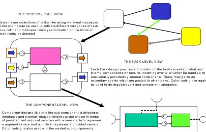
ADLARS describes the structural aspects of architectures in terms of a three-level view, which is illustrated in Figure 1. This is augmented by a behavioural partitioning into what are called interaction themes. Within an interaction theme, all interaction, communication and behaviour is related to one particular theme or purpose. Commonly occurring themes may include, for example, system configuration or system management. There will typically be multiple interaction themes in an ADLARS definition, and individual component or task instances may participate in several themes.
THE SYSTEM-LEVEL VIEW
Systems are collections of tasks interacting via event messages. Color coding can be used to indicate different categories of task. Line color and thickness conveys information on the kinds of event being exchanged
THE TASK-LEVEL VIEW
Each Task design provides information on the task’s event alphabet and internal component architecture. Incoming events will often be handled by functionality provided by internal components. These may generate secondary events which are posted to other tasks. Color coding can again be used to distinguish event and component categories.
THE COMPONENT-LEVEL VIEW
Component designs illustrate the sub-component architecture, interfaces and internal linkages. Interfaces are shown in terms of provided and required services with a semi-circle to represent a required service and a circle to represent a provided service. Color coding is also used with the nested sub-components
At the top level, architectures are viewed as a collection of task instances that execute concurrently and communicate asynchronously. Task instances are created from task templates, which are defined in terms of their input interface and internal component architectures. Within the definition of a task template, we enumerate the associated mandatory, optional and alternative features, and their relationships to contained components and supported messages. Creating a task instance from a task template requires provision of the actual feature sub-set that the instance is required to support. The relationships captured within the task template definition enable the internal structure of the instance to be readily derived.
The component level view represents the lowest level within an ADLARS description. Components are passive software units, characterized by the interfaces that they provide and require. They can be of any size and may contain nested sub-components, to any level of nesting. Once again we define component templates and enumerate the mandatory, optional and alternative features with which they are associated. Component
instances, like task instances, are created by providing actual feature sub-sets.
ADLARS also provides a system environment, which is a structured dictionary of names and terms with supporting textual explanations.
In the following we present the four main parts of the ADLARS description which are:
1. Component Template 2. Task Template 3. System Description 4. System Environment
3.1. Component Template
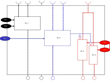
A component template definition embodies a collection of possible component configurations and directly relates these to features occurring in the feature model. Visually, a component template with nested sub-components may appear as in Figure 2.
Features associated with the component are represented as color-coded ellipses with different colors for mandatory, optional and alternative features, respectively.
Sc_1
Sc_2
Op_1 M_1
M_2
Al_1
Al_2
Sc_3
[image:3.612.131.481.384.651.2]Sc_4
Features can be linked to related sub-components. For example optional feature Op_1 is linked to Sc_2. Sc_2’s surround color indicates that it is an optional sub-component, only included in instances of the component which are required to support the optional feature. Alternative feature groups are shown with a linking bar. Interfaces are illustrated using circles (to indicate provided services) and semi-circles (to indicate required services) in a style adopted from UML 2.0. The (semi-)circle color indicates whether the interface element is always supported by component instances, sometimes supported, or is one of a number of alternative interface features.
On the other hand, ADLARS has a textual notation that combines both formal elements and informal elements consisting of free text descriptions. These informal elements are targeted at the needs of non-technical stakeholders, but could also be extracted to form part of the documentation of the architecture, for example during review-based assessment processes. Also, comments (free text) are allowed anywhere in the architecture description using a comment notation similar to the one used with Java and C/C++ ( “//” for single line comments, and “/*” “*/” for multiple line comments) . In the following, the different sections of the component template are described.
Component Template Component_Template_One {
This starts a new Component Template with the name Component_Template_One
interaction themes : { interactionTheme1, interactionTheme2, interactionTheme3};
This is the first section of the component which shows the different interaction themes Component_Template_One is taking part in.
collaborators: { c1, c2, c3 };
By explicitly listing the component collaborators, we can add more input to the analysis of inter-component dependencies within a given inter-component.
features:
{ mandatory: {f1, pf2(int a, byte b), f3}; optional: {f4, f5, f6};
alternatives: {(f7, f8), (f9, f10, f11)}; }
Features can be available or not, based on which functionality is included or not. Also, features can carry values or parameters (parameterised features). So, a non-parameterised feature relates to the availability of some system functionality, i.e. the availability of some components and sub-components. On the other hand, a parameterised feature, in addition to the above, would have a parameterized value(s) that is used to customise dependent Component(s).
One can have mandatory (Kernel), optional, or alternative features. Feature dependencies are captured at a previous stage (at the feature modelling stage).
In the example above, we see the mandatory features f1, pf2 and f3, where pf2 is a parameterised feature, and when available would also provide two values to customise the dependent functionality, an integer a and a byte b.
(f7, f8) is a set of alternative features where only one feature can be selected at a time. Similarly for ( f9 , f10 , f11 ) .
sub-components : {
contents : {
inst c1() : componentTemplate1;
inst c2() : componentTemplate2;
when (supported(f4)) {
inst c3(): componentTemplate3;
} alt
{
(supported(f7) || supported(f11)) {
inst c4() : componentTemplate4; }
(unsupported(pf10) ) {
inst c5(pf10) : componentTemplate5;}
otherwise {
inst c6() : componentTemplate6; }
} }
arrangement :
{ initialize c1 to stateName1,
c2 to stateName2;
when( supported(f1) ) façade(c1,c2); }
}
The sub-components section shows what sub
components to be included within the Component based on the features selected, and in what way components are connected (in the arrangement sub section).
In the contents sub-section, features are explicitly related to sub-components using boolean algebra which provides good flexibility in expressing the relationship between features and components. A feature can be supported or unsupported, enabling us to relate components not only to feature availability, but also absence. This could be useful when expressing negative features (relating functionality to the absence of a feature rather than only the presence of it). This could be of particular importance to commercial product lines where the low-end products (with limited features) must not have access to the features available for the high-end versions.
In the example above, c1 is a kernel component (available in all products within this family) of type componentTemplate1. Similarly for component c2. c3, on the other hand, is only available when feature f4 is selected and so on.
The arrangements sub-section provides a robust mechanism for connecting together sub-components using standard or user defined design patterns. In the example above, components c1 and c2 are connected using the façade pattern. For basic component connectivity, ADLARS syntax can be used; however, for more advanced and complex compositions, a dedicated language (called PATTERNAL) is used to create custom connections and patterns. PATTERNAL is currently being developed within our research group.
interface : {
transition states : {
stateName1 : "relevant information" ; stateName2 : "relevant information" ; }
services : {
provided : { {sc1}::service1, service2,
service3 );
required : { service3, service6 }; }
behaviour : {
stateName1 : {
// provides service1 and goes to stateName2 service1 > stateName2;
// relating components to state transition {sc1, sc2} :: service2 > stateName2; service3; // remains at the same state }
stateName2 : {
service4 ;
service3 > stateName1;
{sc2} :: service5 > stateName1; }
} }
Finally, a component template’s interface is described in terms of the services it provides/requires. An interface can be in different states (transition states) which could affect the services the component can provide/require. The interface states are described in the ‘transition states’ section, the services required/provided are listed in the ‘services’ section and described in more details in the ‘system environment’ section (see later). The transitions among the states and the services required/provided in each state are described in the ‘behaviour’ section. Whenever a service name is pre-qualified with a sub-component name, this means that the service is only available if the sub-component is available. This is an indirect way to correlate service availability with system features (as the availability of the sub-component is directly dependent on available features).
3.2. Task Template
Task template definitions have many similarities with component template definitions. Interaction themes, collaborators and features supported are specified in a similar way. Like component templates, a task template has an associated characteristic feature set. Likewise, the definition of the internal component contents has the same form as that of the sub-component contents section within a sub-component template definition.
Task template definitions differ in having a major section concerned with the definition of the task’s event alphabet. This is the repertoire of event messages that the task expects to receive and is prepared to handle. The event alphabet definition section comprises sub-sections defining the task template’s input alphabet and its output alphabet.
As ADLARS was defined with real-time systems in mind, where time is as important as functionality, detailed information of event timing is captured as well as the recovery procedure.
Below is an example of a Task Template interface:
input alphabet : {
ieventName1 : {
data : {
byte : (40 ~ 1500) : "information …"; string : 64 : "information …"; }
sink component : c1;
implications : "description …";
occurrence : periodic(500);
deadline : n/a;
response : {
c1 >> {oeventName1}; }
recovery : {
margin : 2 ms;
action : c3 >> {oeventName2}; }
}
ieventName2 : {
data : n/a;
sink component : c3;
implications : "description …";
occurrence : random;
deadline : 2000;
response :
{
c1 >> {oeventName1}; c3 >> {oeventName2}; }
} }
output alphabet : {
oeventName1 : {
data : {
byte : (0 ~ 1025) : "information…"; string : 128 : "information…"; }
source component : c2;
occurrence : triggered(500);
deadline : n/a; }
{c3}::oeventName2 : {
data : {
byte : (0 ~ 1025) : "information…"; string : 128 : "information…"; }
occurrence : random;
source component : c3;
deadline : n/a;
Input and output events may be pre-qualified by a set of components to indicate that task instances can only handle these events when the specified components are present. In the example above, the output event oeventName2 is only supported when component c3 is available.
The events are also dependent on the system feature set. Even though we don't see it explicitly, events implicitly relate to the feature set via the dependability on components (as shown above).
Events often carry data and an important aspect of the definition of an input event is the decomposition of its data. Since it is common, in real-time embedded applications, to pack information into the minimum space required, individual bits may be significant and we allow data fields to be described in terms of groups of bits. Variable length fields are also allowed. Also included is a definition of the expected pattern of occurrence of events: random, periodic, triggered, or at specific regular time intervals. Events may have associated deadlines and this information is also stored. Finally, we provide a linkage between arriving events and the internal subcomponents (sink component) within the task. Execution of event handling functionality may cause output events to be generated and the names of these events are also indicated (source component). More detailed information about output events is provided in the output alphabet section.
In the example above, we notice that the arrival of the input event ieventName1 would be responded to by the generation of oeventName1 (by c1). If ieventName1 doesn’t arrive within 2 ms (specified in the recovery subsection - margin) from the expected arrival time, a recovery procedure is executed (in this case, the generation of oeventName2 by c3).
3.3. System Description
A system description layer forms the top level in an ADLARS architecture description. A system description contains a definition of all the tasks in the system, along with any customizing feature sets that they require. It also contains a listing of connections and the event names that pass along the connections.
There may be multiple task instances derived from the same task template, and multiple event communications between any two tasks. Color coding is used to identify event categories.
In the following, we present the contents of the system description layer with inline explanation of each section or keyword:
system description ("My_System") {
Defining a new system called My_System.
TaskTemplate1 task1Inst1(f1, f2),
task1Inst2(), task1Inst3(f3);
TaskTemplate2 task2Inst1(f1,f5);
Creating different Tasks from Task Templates by choosing the right feature set.
synchronized TaskTemplate3 task3Inst1();
The synchronized keyword means a synchronized communication with the Task instance (task3Inst1 in the above example), i.e. a one by one communication with other tasks (similar to the concept of synchronization in Java multithreaded applications).
After creating the Task instances from Task Templates, we proceed to create the product architecture (sometimes referred to as system configuration) by connecting the different Tasks using the appropriate system alphabet which is defined in the system environment section (explained next). To connect two different Tasks you need to specify the Task name and event type as shown below.
connect(task1Inst1, task3Inst1)
using (eventType1);
connect(task1Inst2, task2Inst1)
using (eventType2);
It is also possible to create blocks of synchronized communication rather than synchronized Tasks only as shown below.
synchronize {
connect(task1Inst1, task3Inst1)
using (eventType1);
connect(task1Inst2, task2Inst1)
using (eventType2); }
init(task1Inst1);
wait(100);
init(task2Inst1);
wait(100);
run(task1Inst1, task2Inst1);
3.4. System Environment
The System Environment section of ADLARS contains the information that is relevant to the system as a whole rather than specific Task or Component Templates. The System environment contains five sub- sections:
- Features - Eventtypes - Service definition - Interaction themes - Polices
Starting with the features section, it provides a listing of all the features available in the system feature model (all optional, mandatory and alternative features) along with a brief textual description of each feature (for system documentation purposes). Within an industry, different groups working on different stages of the product development lifecycle might refer to the same feature with different names, even groups working on the same stage of the development process, but within different departments might still refer to the same feature with different names. That is why we introduced the alternative names property in the feature definition section to keep track of the feature and alleviate unwanted repetition.
features
{
feature1: {
description: "feature description...";
alternative names:
{Model1.Name1, Model2.Name2 }; }
feature2: {
description: "feature description...";
alternative names:
{Model1.Name2, Model2.Name5 };
} // etc. }
The event types section defines the different events exchanged within the system:
event types
{
signal : ident(8);
message : [ident(8), data(24)]; long_message : [ident(16), data(112)]; }
The service definition section defines the different services used in the system. Services are abstractions of function names. Each service is defined by a unique name, textual description, the function name it abstracts, and a list of the services required along with a textual description of each as shown below.
service definition
{
serviceName1: {
description: "service description";
invocation: "int functionName(int x, double y)";
service requirements : {
"int requiredFunction1(double x)" : "required function description";
"double requiredFunction2()" : "required function description"; }
}
// and so on }
The interaction themes section contains the definition of the different interaction themes available in the system. An interaction theme is defined by a unique name and a textual description:
interaction themes
{
interactionTheme2 : "textual Description"; }
Finally, an optional set of policies employed by the system can be defined in this section. The policy definition is a simple free textual description which is used primarily for architecture documentation purposes.
policies
{
policy1 : "policy description..."; policy2 : "policy description..."; }
4. Discussion
ADLARS is a work in progress rather than a finished product and this paper has provided just an outline of the language. Its intended application is the definition of flexible architectures for families of software systems. It is an intermediate design notation, for use along with feature-oriented domain modeling. Compared to other notations, its main innovation is the emphasis on capturing the relationships between features and architecture. At its core is the relational model which links features with architectural structure, interfaces or event alphabets, and customizing parameters. Task or component template definitions embody a set of such relationships.
It is worth considering how the language may be used within a product line engineering process. It is envisaged that an ADLARS reference architecture for an intended product family would be designed and specified as part of the domain engineering process. This would come after domain modeling so that the complete feature model would be available. Task and component templates would be defined at this stage, complete with feature dependencies. At the application engineering phase, creating instances from templates requires only the appropriate feature set, which may be obtained as a simple set intersection operation using the specific feature set for the intended product. Thus capturing feature relationships in the reference architecture description, as ADLARS does, makes the task of deriving product-specific architectures, entirely straightforward.
Much work remains to refine aspects of the ADLARS language and provide supporting tools. In the longer term, it is intended to further extend the language to provide better support for the use of generic architectural entities such as design patterns. Patterns play a major role in framework architectures, which must be regarded as a form of product line
architecture. Also, more work is to be done on the real-time aspects of the language and to clearly demonstrate how real-time analysis techniques such as Rate Monotonic Analysis (RMA) could be applied to ADLARS described architectures.
5. Summary
ADLARS is an architecture description language that has been designed to support the description of families of software systems. It has facilities which allow the relationships between the system features and its architecture to be explicitly defined.
The language views Software Architectures to be existing in a three dimensional space: concurrency, structure and behavior, and provides the necessary capabilities to capture these dimensions.
Concurrency is conveyed in Tasks. Tasks are concurrently executing units that communicate through event passing. Tasks usually contain information like: Interaction themes, Features supported, Components and Input/Output alphabets. Interaction themes [19] are used to partition a Task’s interface (or port) into multiple planes each of which is concerned with a specific theme. There are several benefits for using interaction themes such as separation of concerns, reuse, controlled propagation of changes etc. The Features supported section contains a list of features from the candidate architecture’s feature model. Features are classified into mandatory (always supported by the Task) optional (may or may not be supported by the Task), and alternative (alternative features). The Components section is used to describe the passive internal components which produce the functionality that is invoked by the Task in response to arriving events. The Input/Output alphabets section of the Task lists the accepted and generated events by the task with their corresponding rates of occurrence.
interface of a component in terms of services provided/required.
And finally, behavior is captured within interaction themes. As we previously mentioned, each interaction theme bundles a part of the system’s interactions that are concerned with a specific behavior.
6. Acknowledgments
The authors would like to thank the SEW-29 reviewers for their valuable comments.
7. References
[1] L. Bass, P. Clements, and R. Kazman, Software
Architecture in Practice. Reading, MA: Addison-Wesley, 1998.
[2] P. Clements and L. Northrop, "A Framework for Software Product Line Practice, Version 3.0," Software Engineering Institute, Carnegie Mellon University, Pittsburgh, PA 2000.
[3] M. Davis, "Reengineering and the Product Line Approach to Software Development," Boeing Defense & Space Group, Seattle, WA 1996.
[4] F. Bachmann, M. Goedicke, J. C. S. d. P. Leite, R. L. Nord, K. Pohl, B. Ramesh, and A. Vilbig. A Meta-model for Representing Variability in Product Family
Development. Proceedings of the 5th International
Workshop on Software Product-Family Engineering PFE 2003,, Siena, Italy, November 2003.
[5] M. Becker. Mapping Variabilities onto Product Family Assets. Proceedings of the International Colloquium of the Sonderforschungsbereich 501, University of Kaiserslautern, Germany, March 2003.
[6] J. Bosch, G. Florijn, D. Greefhorst, J. Kuusela, H. Obbink, and K. Pohl. Variability Issues in Software
Product Lines. Proceedings of the 4th International
Workshop on Product Family Engineering, Berlin, Germany, 2002.
[7] K. C. Kang, S. G. Cohen, J. A. Hess, W. E. Novak, and A. S. Patterson, "Feature Oriented Domain Analysis (FODA) feasibility study," Software Engineering Institute, Carnegie Mellon University CMU/SEI-90-TR-21, 1990.
[8] P. Clements and L. M. Northrop, "A Framework for Software Product Line Practice - version 2," Software Engineering Institute, Carnegie-Mellon University 1999.
[9] J. Sodhi and P. Sodhi, Software Reuse: Domain Analysis and Design Process: McGraw Hill, 1999.
[10] D. Garlan, R. Monroe, and D. Wile, "Acme:
Architectural Description of Component-Based Systems," in Foundations of Component-Based Systems, G. T. Leavens and M. Sitaraman, Eds.: Cambridge University Press, 2000, pp. 47-68.
[11] S. Vestal, "MetaH Reference Manual," Honeywell Technology Center, Minneapolis, MN 1994.
[12] R. v. Ommering, F. v. d. Linden, J. Kramer, and J. Magee, "The Koala Component Model for Consumer Electronics Software," IEEE Computer, pp. 78-85, March 2000.
[13] D. C. Luckham. Rapide: A Language and Toolset for Simulation of Distributed Systems by Partial Orderings
of Events. Proceedings of DIMACS Partial Order
Methods Workshop IV, Princeton University, July 1996.
[14] R. J. Allen, "A Formal Approach to Software
Architecture." Pittsburgh, PA: Carnegie Mellon University, May 1997.
[15] K. C. Kang, S. Kim, J. Lee, and K. Lee, "Feature-Oriented Engineering of PBX Software for Adaptability and Reusability," Software Practice and Experience, vol. 29(10), pp. 875-896, 1999.
[16] K. Lee, K. C. Kang, W. Chae, and B. B. Choi, "Feature-based approach to object-oriented engineering of
applications for reuse," Software Practice and
Experience, vol. 30, pp. 1025-1046, 2000.
[17] D. Fey, R. Fajta, and A. Boros. Feature Modeling: A Meta-model to Enhance Usability and Usefulness.
Proceedings of the 2nd International Conference on Software Product Lines (SPLC2), San Diego, USA, August 2002.
[18] N. Medvidovic and R. N. Taylor, "A classification and Comparison Framework for Software Architecture
Description Languages," IEEE Transactions on
Software Engineering, vol. 26, 2000.
[19] M. Jazayeri, A. Ran, and F. v. d. Linden, Software