PMSM Drive using Direct Torque Control with SVM
Kajal Sahu
1Preeti Gupta
21
Research Scholar
2Assistant Professor
1,2Department of Electrical Power Engineering
1,2
OCT, Bhopal, India
Abstract— Permanent magnet synchronous motor drive has two controls; vector control and direct torque control. A Direct Torque Control technique by using Space Vector Modulation (DTC-SVM) for permanent magnet synchronous machine (PMSM) drive is proposed in this paper. DTC-SVM technique improves the performance of PMSM, which provides low torque and flux ripple and fixed switching frequency. The effectiveness of the proposed scheme is validated in Matlab/Simulink, environment.
Keywords: PMSM, DTC, DTC-SVM, Torque Ripple, Flux Ripple, Fixed Switching Frequency
I. INTRODUCTION
The control scheme for PMSM includes director control and vector control out of which direct torque control is popular. Direct Torque Control (DTC) method has been first proposed and applied for induction machines in the mid- 1980’s as reported in [1]. This concept can also be applied to synchronous drives [2]. Indeed, in the late 1990s, DTC techniques for the interior permanent magnet synchronous machine appeared, as reported in [3].Permanent magnet (PM) synchronous motors are widely used in high-performance drives such as industrial robots and machine tools to their advantages as: high efficiency, high power density, high torque/inertia ratio, and free maintenance. In recent years, the magnetic and thermal capabilities of the PM have been considerably increased by employing the high coercive PM material [4]. For some applications, the DTC becomes unusable, despite it significantly improves the dynamic performance of the drive compared to the vector control due to torque and flux ripples. Indeed, hysteresis controllers used in the conventional structure of the DTC generates a variable switching frequency, causing electromagnetic torque oscillations [5], this frequency is also varying with speed, load torque and hysteresis bands selected [6]. In addition, a high sampling frequency needed for digital implementation of hysteresis comparators and a current and torque distortion caused by sectors changes [7]. Several contributions have been proposed to overcome these problems, by using a multilevel inverter: more voltage space vectors available to control the flux and torque. However, more power switches are needed to achieve a lower ripple and almost fixed switching frequency, which increases the system cost and complexity [8]-[9]. In [10] and [11], two structures of modified DTC have been proposed to improve classical DTC performances by replacing the hysteresis controllers and the commutation table by a PI regulator, predictive controller and Space Vector Modulation (SVM). In this paper, a modified DTC algorithm with fixed switching frequency for PMSM is proposed to reduce the flux and torque ripples. It is an extension of the modified DTC scheme for the PMSM proposed by the authors in [12]. The performance of the basic DTC and the proposed DTC scheme is analyzed by modeling and simulation using MATLAB.
II. DTC AND DTC-SVM STRUCTURES
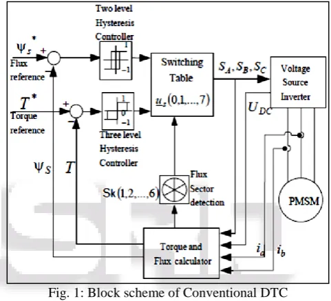
[image:1.595.306.547.248.467.2]Figures 1 represents two system configuration of DTC controlled PMSM drive respectively; both of them use the same flux vector and torque estimators. However, torque and flux hysteresis controllers and the switching table are replaced by a PI torque controller and a predictive calculator of vector voltage reference to be applied to stator coils of the PMSM.
Fig. 1: Block scheme of Conventional DTC
The basic idea of direct torque control is to choose the appropriate stator voltage vector out of eight possible inverter states (according to the difference between the reference and actual torque and flux linkage) so that the stator flux linkage vector rotates along the stator reference frame (dq frame) trajectory and produces the desired torque.
In the proposed scheme of DTC-SVM with speed loop control, shown in Figure.2, after correction of the mechanical speed through a PI controller, the torque PI controller delivers Vsq voltage to the predictive controller and
also receives, more the reference amplitude of stator flux Өsr,
information from the torque and flux estimator namely, the amplitude and position ϴs of the actual stator flux and
measured current vector.
Fig. 2; Phasor diagram of a non-salient pole synchronous machine in the motoring mode.
From the motor voltage equation, for the omitted voltage drop on the stator resistance, the stator flux can by express as:
dᴪs
dt
(1)
Taking into consideration the output voltage of the inverter in the above equation it can be written as:
ᴪs=∫ uv t
0 dt (2)
Where
Uv = { 2 3udce
j(v−1)ᴫ/3 v = 1 … 6
0 v = 0,7 (3)
Equation (3) describes eight voltage vectors which correspond to possible inverter states. These vectors are shown in Fig. 3. There are six active vectors U1-U6and two zero vectors U0, U7 Vectors.
Fig. 3: Inverter output voltage represented as a space vector It can be seen from (eq.2), that the stator flux directly depends on the inverter voltage. By using one of the active voltage vectors the stator flux vector moves to the direction and sense of the voltage vector However, in this case the control algorithm choose correct voltage vectors, thanks to that waveform is close to be sinusoidal. In this simulation a low sampling frequency is used (0.5 kHz) for better presenting the effect. In PMSM motor the rotor flux is slowly moving but the stator flux can be changed immediately. In
changed thanks to the appropriate selection of voltage vector. There are the general bases of the direct flux and torque control methods. Those consideration and above equations can be used in analysis of the classical DTC algorithms as well as in new proposed methods.
III. SIMULATION RESULTS AND DISCUSSION
Permanent magnet synchronous motors (PMSM) are widely used in low and medium power applications such as computer peripheral equipments, robotics, adjustable speed drives and electric vehicles. The growth in the market of PMSM motor drives has demanded the need of simulation tool capable of handling motor drive simulations. Simulations have helped the process of developing new systems including motor drives, by reducing cost and time. Simulation tools have the capabilities of performing dynamic simulations of motor drives in a visual environment so as to facilitate the development of new systems
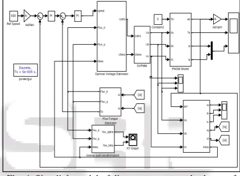
Fig. 4: Simulink model of direct torque control scheme of PMSM drive
The model of direct torque controlled permanent magnet synchronous motor (PMSM) drive are developed in MATLAB environment with Simulink & PSB tool boxes to simulate the behavior of drive with PI controller. The MATLAB model of DTC based system is shown in figure 4.Each subsystem of the main simulation model such as Permanent magnet synchronous motors space vector pulse width modulated inverter (SVPWM) inverter, speed controller, torque & flux estimator etc., have its own model in Simulink, according to the set of equations, already discussed in the previous chapters.
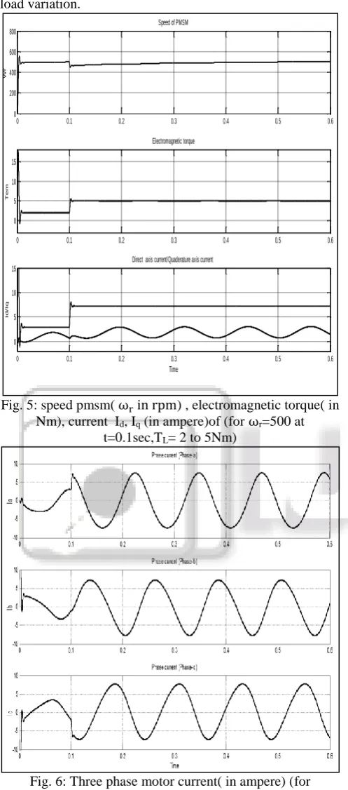
A. Performance of PMSM Drive with Sudden Change in Load Torque:
In figure 5 shows the speed & torque response of Permanent magnet synchronous motors drive for a set speed of ωr
=500rpm with sudden change in load torque occurs at (t=0.1 sec) from 2 to 5 Nm. (TL = 2 to 5Nm) the sudden application
of load on the motor shaft cause a small dip in the rotor speed, which recovers quickly resulting in zero steady state speed error.
-K-rad-rpm
Discrete, Ts = 5e-005 s.
powergui PI PI f lux_d f lux_q theta f lux_alpha f lux_beta inverse park transformation
XY Graph Ualf a Ubeta Ua Ub Uc SVPWM 500 Ref Speed Tm Va Vb Vc we Te id iq PMSM Model speed Flux_d Flux_q theta Ualf a Ubeta
Optimal Voltage Estimator
[image:2.595.306.548.282.459.2]recovers the rotor speed back to reference value under such load variation.
Fig.5: speed pmsm( ωr in rpm) , electromagnetic torque( in Nm), current Id, Iq (in ampere)of (for ωr=500 at
t=0.1sec,TL= 2 to 5Nm)
Fig. 6: Three phase motor current( in ampere) (for ωr=500rpm at t=0.1sec,TL=2 to 5Nm)
[image:3.595.55.542.65.645.2]The stator phase voltages are maintained constant throughout the change in load torque as shown in fig 7, which is the necessary condition for speed control in all ranges.
Fig. 7: Three phase stator voltage( in volt) (for ωr=500 at
[image:3.595.308.549.68.310.2]t=0.1sec, TL=2 to 5Nm)
Fig 8 shows the X-Y axis flux trajectory; there is a change in the circumference as the load changes.
Fig. 8: Flux trajectory between α −
axis flux (x axis ) and β − axis Flux (y axis) X (For ωr=500 at t=0.1sec,TL=2 to 5Nm)
It is observed from the above curves that PMSM operates at constant speed under varying told torque and the current drawn by motor linearity varies with the applied load torque on the PMSM.
B. Performance of PMSM Drive under Speed Change (𝜔r =800rpm to 250rpm)
In this test system the reference speed is changed from ωr
= 800 to 250 rpm at t = 0.1 sec while the load torque is remained constant at TL =2 Nm. The response of motor speed,
electromagnetic torque in the fig-9.
It clear from fig-9 that machine oscillations for a few cycle and finally settles to steady state reference value of ωr
= 250 rpm. There is a dip in machine electromagnetic torque with sudden change in machine speed and it reaches to a value equal to the load torque very fast.
0 0.1 0.2 0.3 0.4 0.5 0.6
0 200 400 600 800
Wr
Speed of PMSM
0 0.1 0.2 0.3 0.4 0.5 0.6
0 5 10 15
T
e
m
Electromagnetic torque
0 0.1 0.2 0.3 0.4 0.5 0.6
0 5 10 15
Time
I
d
/
I
q
[image:3.595.296.548.71.558.2] [image:3.595.45.294.82.646.2]Fig.9: speed of pmsm( in rpm), electromagnetic torque (in Nm), current Id,Iq ( in ampere) (for ωr=800 to 250 rpm at
[image:4.595.308.549.67.289.2]0.1sec, TL=2Nm)
Fig 10 shows the reference voltages α- axis voltage (Ualfa) and voltages β- axis voltage (Ubeta) as generated by
optimal voltage estimator block. This voltage is used as reference for SV-PWM Inverter, for sector determination & generation of desired output-voltage to controls the speed of PMSM drive.
Fig.10: the reference voltages α- axis voltage (Ualfa) in volt
and β- axis voltage (Ubeta)( in volt)(For ωr=800 to 250 rpm
at 0.1sec, TL=2Nm)
Fig-11 shows the three phase stator voltage, the magnitude and frequency of stator voltages changes; as the reference value of speed & load torque changes, in order to match the desired speed & torque profile.
Fig. 11: Three phase stator voltage (in volt) (for ωr= 800 to
[image:4.595.46.290.67.329.2]250 rpm at 0.1sec, TL=2Nm)
Fig-12 shows the x-y graph between α & β - axis flux of PMSM drive. When the motor starts the trajectory will observe a sudden oscillation as shown by arrow direction.
Fig. 12: Flux trajectory between α −
axis flux (x axis ) and β − axis Flux (y axis) (for ωr=800
to 250 rpm at 0.1sec, TL=2Nm)
IV. CONCLUSION
In this paper it was presented a method of utilization of Space Vector Modulation for the Direct Torque control of a PMSM. To determine the reference voltage, a simple algorithm was proposed, based on the torque error and the flux phase angle. The results show that a smooth steady state operation was obtained when using the proposed method. Moreover, a constant inverter switching frequency is ensured by using SVM topology. A modified direct torque control (DTC-SVM) with speed loop has been proposed and validated in Matlab/Simulink. The torque and flux ripples are agree with the simulation results, additionally the implementation shows that the speed and torque dynamic state is the same as the simulation results. Basic and modified DTC assure very good
0 0.1 0.2 0.3 0.4 0.5 0.6
0 500 1000
Wr
Speed of PMSM
0 0.1 0.2 0.3 0.4 0.5 0.6
-15 -10 -5 0 5
T
e
m
Electromagnetic torque
0 0.1 0.2 0.3 0.4 0.5 0.6
-10 -5 0 5 10
Time
I
d
\
I
q
[image:4.595.305.544.336.516.2] [image:4.595.51.285.425.614.2]REFERENCES
[1] M. R. Zolghadri and D. Roye “ A fully digital sensorless direct torque control system for synchronous machine,’’ Electric Power Components and Systems, 1532-5016, vol 26, Issue 7, Pages 709 – 721, 1998.
[2] D. Swierczynski, M.Kazmierkowski, and F. Blaabjerg, “DSP based Direct Torque Control of permanent magnet synchronous motor (PMSM) using space vector modulation (DTC-SVM),” International Symposium on Industrial Electronics (ISIE) vol.3, pp, 723 – 727, Nov 2002.
[3] L. Tang, L. Zhong, M. F. Rahman, and Y. Hu “A novel direct torque control for interior permanent-magnet synchronous machine drive with low ripple in torque and flux a speed-sensorless approach”, IEEE Transactions on industry applications, vol. 39, No. 6, Nov. 2003. [4] T. J. Fu and W. F. Xie “A novel sliding-mode control of
induction motor using space vector modulation technique,”, ISA Transaction vol 44, pp 481-490, 2005. [5] K. B. Lee, and F. Blaabjerg “ A modified DTC-SVM for
sensorless matrix converter drives using a simple deadbeat scheme,’’ HAIT Journal of Science and Engineering, vol 2, Issues 5-6, pp. 715-735, published June 2005.
[6] T. J. Vyncke, R. K. Boel and J .A .A. Melkebeek, “Direct torque control of permanent magnet synchronous motors an overview,’’ 3rd IEEE Benelux young researchers symposium in electrical power engineering, Apr 2006. [7] S. V. Zadeh and E.Jalali “Combined vector control and
direct torque control method for high performance induction motor drives,”, Science Direct, Energy Conversion and Management, vol 48, pp 3095-3101, 2007.
[8] H. Ziane, J.M. Retif and T. Rekioua “Fixed-switching- frequency DTC control for PM synchronous machine with minimum torque ripples,’’ Can. J. Elect. Comput. Eng., vol. 33, No. 3/4, Summer/Fall 2008.
[9] Y. Kumsuwan, S. Premrudeepreechacharn, H. A. Toliyat “ Modified direct torque control method for induction motor drives based on amplitude and angle control of stator flux,’’ Elsevier, Electr. Power syst. Res, 2008. [10]L. Ningzhou, W. Xiaojuan and F. Xiaoyun ‘‘an improved
DTC algorithm for reducing torque ripples of PMSM based on cloud model and SVM,’’ International Conference on Multimedia Information Networking and Security, 2010.
[11]S. Belkacem, B. Zegueb and F. Naceri ‘‘Robust non- linear direct torque and flux control of adjustable speed sensorless PMSM drive based on SVM using a PI predictive controller’’, Journal of Engineering Science and Technology Review 3 (1) (2010) 168-175, Accepted 20th July 2010.