Evolution, Geometry and Formative Processes of
Depositional Elements in Niger Delta Slope Settings
John Olaolu Akindulureni*, Adekunle Abraham Adepelumi, Uzochukwu Kingsley Benjamin
Department of Geology, Obafemi Awolowo University, Ile-Ife 220002, Nigeria
Copyright©2018 by authors, all rights reserved. Authors agree that this article remains permanently open access under the terms of the Creative Commons Attribution License 4.0 International License
Abstract
The depositional elements in the slope settings of Niger Delta were assessed in this study in order to improve current understanding of their evolution, geometry and formative processes. Well log analysis revealed thick sequences of shale, interbedded with relatively thin hydrocarbon-bearing turbidite sands in the studied interval. Depositional elements delineated include a 32km long submarine incised valley, an erosional channel belt and a leveed channel. Other features identified include scallops, terraces, linear grooves as well as scours of mass-transport deposits (MTDs). It was deduced that the submarine incised valley formed by gradual incision made by erosive turbidity flows and evolved in four post-incision phases. The erosional channel belt was interpreted to have formed by cut-and-fill processes, with no evidence of levees. The leveed channel characterized by low-amplitude channel-axis reflections and brighter levee amplitude signatures indicated the presence of thin sands in the levee areas and fine-grained channel-axis deposits. Fair to good reservoir potential of the fill-deposits were inferred from log responses and seismic amplitude signatures of the sand fill-deposits within the mapped interval. Results from this study show that the identified depositional elements formed from repeated erosive turbidity flows and other mass transport processes.Keywords
Depositional Element, Submarine Incised Valley, Mass-Transport, Channel, Turbidity Flows1. Introduction
Depositional elements are the basic components of ancient and modern turbidite systems that can be mapped and recognized in subsurface and marine settings, as well as outcrops [1]. They include canyons, channels, overbank
sediments (outer and inner levees), frontal and crevasse splays, mass-transport complexes, condensed sections, slides, debris flow lobes and sheets. The depositional elements in a variety of deepwater regions have been described by a number of authors including [2-7]. These depositional elements are important constituents of depositional systems as they have been reported to influence the architecture and nature of reservoirs where present.
A variety of depositional elements in Niger Delta slope settings are described in this paper including a submarine incised valley, a low-sinuosity erosional channel belt, and a leveed channel. Other features such as erosional scallops, erosional and fault-scarped terraces, linear grooves as well as scours of mass-transport deposits (MTDs) are also illustrated. The sediments that comprise these deposits were probably transported by the Niger River and its distributaries on to the shelf and deepwater to depths exceeding 1000 m. The study area is located about 120 km offshore southwestern Niger Delta, beyond the continental shelf, at about 1300 m water depth (Figure 1). In these deepwater settings, the Benin formation is absent, and the Akata Formation is diachronously overlain by deepwater turbidite channel complexes, debris flows and shales of the Agbada Formation [8].
Figure 1. Regional map of the Niger Delta, showing the study area (Modified after [10])
Figure 2. Mapped surfaces within the volume (SF- Seafloor; H1- Horizon 1; H2- Horizon 2)
2. Materials and Methods
The 3D seismic data covers an area of 812 km2 on the
western Niger Delta slope (Figure. 1). The line spacing is 25 m in both the inline and cross-line directions. The dominant frequency of the studied shallow section is 50 Hz and thus the tuning thickness (l/4) is about 10 m. Seismic attributes, including dip magnitude, amplitude, edge detection, average energy, were used to reveal depositional and deformational features on three mapped surfaces- Seafloor (SF), Horizon 1 (H1), and Horizon 2 (H2) (Figure 2). Lithological interpretation of the seismic facies was done using techniques employed by [10], calibrated by one well located in the central part of the area. The time-to-depth conversion was done using the checkshot data from available well data. Mapping and interpretation of depositional elements in this study was
limited to the 1000 ms TWT interval from the seafloor. Gamma-ray (GR) and resistivity log were used for lithologic identification and gross depositional environment interpretations. Core data was not available to calibrate the well-logs.
3. Results
conditions in deep-marine settings. The few and thin sands within the unit were interpreted to represent short-lived periods of energy burst from turbidity currents in the otherwise quiet environment. The lithofacies were interpreted to be composed essentially of hemipelagic shales and gravity-flow sands, essentially turbidites. Based
[image:3.595.128.472.158.665.2]on the gross depositional facies/ environments and log responses of mud-rich deep-marine clastic systems classification of [11], the sand units identified within the well were interpreted as possible channel fills of slope fans (Figure 3).
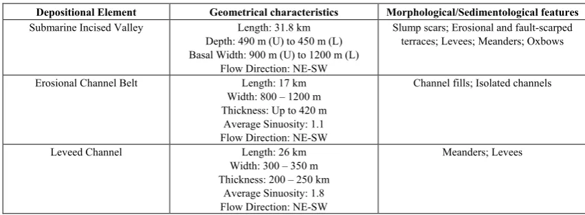
Table 1. Characteristics of identified depositional elements (U: Valley upper reaches; L: Valley lower reaches)
Depositional Element Geometrical characteristics Morphological/Sedimentological features
Submarine Incised Valley Length: 31.8 km Depth: 490 m (U) to 450 m (L) Basal Width: 900 m (U) to 1200 m (L)
Flow Direction: NE-SW
Slump scars; Erosional and fault-scarped terraces; Levees; Meanders; Oxbows
Erosional Channel Belt Length: 17 km Width: 800 – 1200 m Thickness: Up to 420 m
Average Sinuosity: 1.1 Flow Direction: NE-SW
Channel fills; Isolated channels
Leveed Channel Length: 26 km Width: 300 – 350 m Thickness: 200 – 250 km
Average Sinuosity: 1.8 Flow Direction: NE-SW
Meanders; Levees
3.2. Depositional Elements
The depositional elements identified in this study include a submarine incised valley and associated levees, an erosional channel belt, and a leveed channel (Table 1). These depositional elements were well expressed on the 3-D seismic data, thus enabling the description of their geomorphic and stratigraphic characteristics such as their external form and architecture. The submarine incised valley was observed on the seafloor (SF) and was associated with features such as scallops and terraces. The dip magnitude attribute map of the seafloor revealed that the seafloor dips to the west. The shallowest part occurs NE on a bathymetric high, while the deepest part occurs SW within an incised valley. The edge detection attribute map of the seafloor, which isolated the areas on the horizon where subtle changes in surface topography occurred, revealed several features and important elements, such as faults, seafloor mounds, scallops, erosional and fault-scarped terraces (Figure 4). The faults expressed on the seafloor had arcuate geometries and correspond to the surface expression of the normal faults that characterize the study area. The presence of seafloor mound, indicative of previously erupted mud volcanoes underlain by diapirs, suggested the presence of a reservoir at depth [8].
4. Discussion
4.1. Submarine Incised Valley
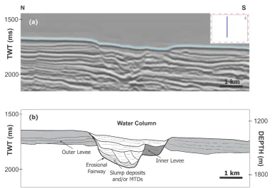
Submarine incised valleys are underwater slope conduits incomparably deeper than the system largest channels, cut into earlier deposits by excessively erosive sediment-gravity flows [12,13]. Submarine incised valleys have been described by various authors [5,14]. The submarine incised valley mapped is located within the upper 600 ms TWT (575 m) of strata and has a NE-SW trend. The 3-D seismic volume captured a 32 km long segment of the submarine incised valley. Although the precise age of the incised valley is unknown due to unavailable age-calibration data, it is suggested that it was
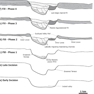
active in the Pleistocene-Recent, given its occurrence on the seafloor. It had a maximum thickness of about 500 ms TWT (490 m) at the valley axis, and a distance of 2 km to 3.5 km between valley walls. It consists of an erosional fairway at its base (Figure 5), and erodes through parallel-bedded, in places normal-faulted, strata inferred to correspond to predominantly mud-prone slope sediments. The submarine incised valley comprises valley-fills and channel belts which enabled the interpretation of its evolution and channel fill-history. From this study, the evolution of the submarine incised valley was proposed as divided into an episode of incision, followed by a four-phase fill history (Figure 6). The evolution phases were defined on the basis of their unique characteristics such as channel architecture, planform geometry, nature of deposits and type of fill-materials. The incision phase was revealed by the presence of erosional scallops and terraces on the walls of the submarine valley.
a. Incision
Figure 4. Edge detection attribute map of the seafloor, with associated depositional features and elements (X - Well location)
[image:5.595.105.490.444.709.2]Figure 6. Schematic drawing showing the evolution and fill-history of the submarine incised valley
Two types of terraces were identified on the seafloor within the region of the submarine valley walls; erosional terraces and fault-scarped terraces. The erosional terraces were probably rejuvenation features resulting from channel entrenchment into flat-lying strata [10]. Several relatively horizontal erosional terraces, ranging in height from 50 m to 150 m above the thalweg, were also present around the margin of the submarine valley (Figures 4 and 6b). It is suggested that these erosional terraces originated during the incision of the submarine valley forming relatively flat benches consisting internally of strata deposited prior to the incision of the submarine valley. These erosional terraces commonly become sites of deposition of prominent inner levees [5]. The fault-scarped terraces are terraces induced by movement of strata along the fault planes that border the submarine valley. These terraces were identified at the margin of the submarine valley indicating that the geometry of the valley walls was also influence by the presence of normal faults that extended to the seafloor.
Scallops characterized the margins of the submarine valley (Figure 4). These scallops were inferred to have developed from direct cut-bank erosion from incised channels at the base of the submarine valley during incision, and possibly from slumps that left behind curved slump scars when sediment was shed from the submarine valley
walls forming slump deposits.
a. Phase 1 (Deposition of slump/Mass-transport deposits)
The interval directly above the floor of the erosional fairway consists of a zone of discontinuous high amplitude reflections, in some areas transparent to chaotic. Horizon-slices indicated that the discontinuous high amplitude reflections consist of discontinuous remnants of sinuous channels confined within the deepest parts of the erosional fairway (Figure 7). This package of reflections was interpreted to correspond to slump deposits and mass-transport deposits (MTDs) that originated from the terraces and scallops during the periods of incision into the substrate, and relic deposits of erosive flows that incised the valley (Figure 6c).
b. Phase 2 (Meandering channel belt)
Phase 1 slump/mass-transport deposits and display lateral migration as well as aggradation within the channel belt (Figure 6d). The channels are 200 m to 450 m wide and 250 m to 350 m deep, with average sinuosity (ratio of channel axis length to channel belt length) of 2.1. The planform channel geometry exhibits regular and smooth-curved meander bends, evidence of bend cut-offs (similar to oxbows in fluvial channels) and appear as moderate to high-amplitude sinuous threads (Figure 8). The sinuous channels are characterized by both meander loop expansion (swing) and down-system meander loop migration (sweep) as they evolved through time, indicating the dynamic nature of the channels as they flowed through the incised valley.
The development of overbank deposits (levees) began in Phase 2 with inner levees onlapping the scalloped margins and terraces of the erosional fairway. The inner levee height varied from 55 m to 370 m. In seismic section, these inner levees were characterized by parallel to sub-parallel high amplitude continuous to semi-continuous reflections, similar to the channel-belt fill, indicating that these were possible sand deposits that resulted from flow overspill from the channel to the terraces/scalloped margins or a result of hydraulic jump within the turbidity currents flowing through the channel [16]. The inner and outer levees showed contrasting acoustic character indicating difference in the composition of the levee deposits. The outer levees draped the erosional terraces along the margin of the erosional fairway and were characterized by downlapping parallel low to moderate amplitude continuous reflections, indicating that the deposits are probably mud-dominated. c. Phase 3 (Passive fill)
Phase 3 was characterized by the deposition of passive aggradational fill and cessation of deposition of the inner levees. The aggradational fill deposits consist of low to moderate amplitude discontinuous reflections that onlap the erosional fairway and inner levee walls (Figure 6e). The thickness of the passive fill within the Phase 3 varied from 100 m to 150 m. Planform images of phase 3 indicated reduced actions of channels and the presence of uniform low amplitude deposits within pronounced valley walls (Figure 7).
d. Phase 4 (Last-stage channel-fill)
The last phase of the incised submarine valley evolution involved the deposition of last-stage channel-fills which were characterized by parallel low amplitude continuous
horizontal reflections, interpreted as mud-prone sediments, deposited on the underlying sediments within the entire incised valley (Figure 6f). Last-stage channel fills are generally deposited by flows differing from those which formed and shaped the channel-belt [17], and hence are genetically unrelated to the deposits of the earlier phases. These channel-fills were identified to be margin-onlapping tabular beds whose deposits are products of bypassing non-incising waning flows.
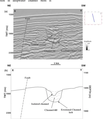
4.2. Erosional Channel Belt
An erosional channel belt extending 17 km long was identified on H1. The channel was 800-1200 m wide and had an average sinuosity of 1.1. The planform geometry of the erosional channel belt, with a NE-SW flow direction, was revealed on the amplitude horizon slice (Figure 9). On the amplitude map, the channel belt occurred as a low-amplitude, single, low sinuous thread/band. In seismic cross section, the erosional belt was a U-shaped feature with fill-deposits characterized by low to high-amplitude continuous to discontinuous reflections suggestive of a combination of mud-prone and sand-prone fill deposits (Figure 10). The channel belt had thickness up to 420 m, and was characterized by isolated channels and channel-fills. The isolated channels formed after the initial deposition of sediments into the erosional channel following cessation of incision and erosion. They are characterized by deposits of low to high amplitude reflections.
The channel belt is interpreted to have formed by cut-and-fill processes, with little or no evidence of levees and with the last-stage channel fills typically mud-prone. The channel belt probably was evolved by incision and erosive action of turbidity currents on the continental slope during a period of low-stand on the continental shelf.
4.3. Leveed Channel
Figure 7. Iso-proportional slices from the amplitude volume, flattened on the seafloor showing the four phases of evolution of the submarine incised valley at different time windows below the seafloor
Figure 8. Meandering channel belt in Phase 2 (iso-proportional slice 200 ms below seafloor) showing the cut-off meander
[image:8.595.200.394.575.731.2]This implies that the channel probably underwent an erosional-aggradational-erosional phase, with the initial and final stages of the channel formation being erosional, marked by the absence of levees, and separated by an aggradational phase accompanied by levees deposition and increased sinuosity. In map view, the channel axis was composed of low-amplitude fill deposits, indicating that the channel fill is probably mud-prone turbidites. In section view, the leveed channel was composed of low-amplitude fill deposits, with high amplitude levee deposits, inferred to be sand-prone sediments (Figure 12). Levee deposits are the largest and most extensive sand-prone depositional element of sinuous channel belts [5], and are thus important as exploration targets and elements of reservoir characterization. The amplitude response of the levees showed a strong contrast with the low-amplitude mud-prone infilling of the channel axis. The top surface of the levees was smooth, indicating an absence of sediment waves common to levees. Levee thickness decreased with distance from the channel, while levee-height along the entire channel varied from 20 m to 60 m.
Levee deposition in deepwater channel belts is
attributed to the overspill of turbidity currents that are conveyed by the channel. These turbidity currents usually spill out of the channel when they become either volumetrically larger than the capacity of the channel or when they are in hydraulic disequilibrium with the channel geometry [18]. These turbidity currents may also spill out excessively in response to the local plugging of channel by MTDs, or the infilling of last-stage channels by sediment prior to channel-abandonment.
The levee overbank beyond the outer bends of the channel meanders had higher amplitude and more lateral extent than the levees formed beyond the inner bends of the channel meanders suggesting that the flow overspill from the channel to the overbank was significantly more active along outer banks, consistent with the observations of [19,20]. The outward-thinning trend of the levees also observed is consistent with observations from leveed channels in many other submarine systems [21,22]. This is attributed to the spill-out of sustained (long-duration), quasi-steady high-competence flows, which is in agreement with the hydraulic conditions for the formation of overbank sediment waves found on levees [23].
[image:9.595.126.459.345.730.2]4.4. Exploration Significance
Deepwater reservoirs occur in three main settings which include channelized systems, channel-levee complexes and sheet complexes (including lobes) [24]. The analyses of the geomorphic and stratigraphic characteristics of depositional elements in this study revealed the presence of both channelized systems and leveed channels, including their associated fill-deposits. Furthermore, lithofacies identification using the available well data revealed the presence of thin sand units which are potential reservoirs targets.
The channel fill-deposits of the meandering channel belts within the submarine incised valley were characterized primarily by high amplitude seismic reflections, interpreted to be sand-rich. The areal extent and distribution of these sand-prone deposits within the meandering channels are dependent on the extent of lateral channel migration and these deposits may form extensive reservoir facies if the meandering channels are laterally interconnected.
The potential reservoirs within the erosional channel belt occur in the isolated channels characterized by moderate to high-amplitude seismic reflections interpreted to be sand-prone sediments. These isolated channels are interpreted to contain isolated channel-fill sandstones which create compartmentalized reservoirs.
[image:10.595.308.541.76.431.2]The levees associated with the high-sinuosity channel were characterized by high-amplitude reflections interpreted as sand-rich deposits. These levee deposits could contain thin reservoir-quality sandstones and be potential exploration targets. These levee sandstone deposits have been described by [25] as “low-resistivity” pay zones, and are best developed in proximal levee settings, especially along outer-channel bends.
Figure 11. (a) Uninterpreted and (b) Interpreted average energy maps showing the leveed channel
[image:10.595.122.470.465.736.2]5. Conclusions
Depositional elements and associated features in slope settings from Niger Delta have been described. The depositional elements include a submarine incised valley and associated inner and outer levees, an erosional channel belt and associated isolated channels, a leveed channel, erosional scallops, erosional and fault-scarped terraces, linear grooves and scours of mass-transport deposits. Well log interpretation revealed two lithologic units within the well, namely shale and sand occurring in the ratio 9:1. The high proportion of shale in the well indicated the deposition of the units in a predominantly low-energy quiet environment. They turbidite sands were interpreted as channel-fills of slope fans.
It was proposed that the submarine incised valley formed from gradual incision by erosive turbidity flows giving rise to a U-shaped, wide-floor (up to 1.2 km) valley with corresponding terraces and evolved in four phases post-incision. These phases were characterized by the deposition of slumps and MTDs, development of sinuous meandering channel belt and inner levees, deposition of passive fill, and deposition of last-stage channel fills. The incision of the submarine valley was demonstrated by the presence of erosional scallops and terraces on the walls of the submarine valley.
The erosional channel belt was a U-shaped feature with fill-deposits and isolated channels characterized seismically by low to high-amplitude continuous to discontinuous reflections. The channel belt possibly formed by cut-and-fill processes, with little or no evidence of levees and the presence of last-stage channel fills typically mud-prone. The channel belt probably was evolved by incision and erosive action of turbidity currents on the continental slope during a period of low-stand on the continental shelf.
The leveed channel was inferred to have developed in three phases; (i) an initial erosional phase characterized by low sinuosity and absence of overbank deposits, followed by (ii) an aggradational phase marked by levee development and increased channel sinuosity, and (iii) another phase of erosion similar to the first phase. This is attributed to a probable local reduction of slope gradient in the middle course of the channel. The deposition of levees in the channel was believed to result from flow-spill of turbidity currents conveyed by the channel.
The interpreted sands of the high amplitude sinuous meandering laterally migrating channel-fills, isolated channel-fills within the erosional channel and levee deposits were inferred to have good hydrocarbon exploration significance.
Acknowledgements
The authors wish to thank Shell Nigeria for providing the dataset. The authors also acknowledge Schlumberger for access to Petrel Seismic to Simulation software. Dele
Falebita, Olumuyiwa Akinsanpe, Babatunde Bukunmi, Oluchukwu Banye and Ufuoma Diakparomre are also thanked for their suggestions and valuable comments during the research and preparation of the manuscript.
REFERENCES
[1] E. Mutti, W. R. Normark. An integrated approach to the study of turbidite systems, in: P. Weimer, M. H. Link (Eds.), Seismic facies and sedimentary processes of submarine fans and turbidite systems: New York, Springer-Verlag, 75–106, 1991.
[2] F. Fonnesu. 3D seismic images of a low-sinuosity slope channel and related depositional lobe (West Africa deep-offshore), Marine and Petroleum Geology, Vol.20, 615–629, 2003.
[3] H. W. Posamentier, V. Kolla V. Seismic Geomorphology and Stratigraphy of Depositional Elements in Deep-water settings, Journal of Sedimentary Research Vol.73, No.3, 367-388, 2003.
[4] V. Kolla, H. W. Posamentier, L. J. Wood. Deep-water and fluvial sinuous channels—Characteristics, similarities and dissimilarities, and modes of formation, Marine and Petroleum Geology, Vol.24, 388–405, 2007.
[5] M. Janocko, W. Nemec, S. Henriksen, M. Warchol, The diversity of deep-water sinuous channel belts and slope valley-fill complexes, Marine and Petroleum Geology, Vol.41, 7-34, 2013.
[6] C. Gong, Y. Wang, D. M. Hodgson, W. Zhu, W. Li, Q. Xu, D. Li. Origin and anatomy of two different types of mass-transport complexes: a 3D seismic case study from the northern South China Sea margin, Marine and Petroleum Geology, Vol.54, 198-215, 2014.
[7] L. Basilone, A. Frixa, E. Trincianti, V. Valenti. Permian-Cenozoic deep-water carbonate rocks of the Southern Tehtyan Domain: The case study of Central Cicily, Italian Journal of Geoscience 135, 171-198, 2016.
[8] K. Graue. Mud volcanoes in deepwater Nigeria, Marine and Petroleum Geology Vol.17, 959–974, 2000.
[9] H. W. Posamentier. Seismic stratigraphy into the next millenium; a focus on 3D seismic data, AAPG Annual Conference, New Orleans, Los Angeles, A118, 2000. [10] M. E. Deptuck, G. S. Steffens, M. Barton, C. Pirmez.
Architecture and evolution of upper fan channel-belts on the Niger Delta slope and in the Arabian Sea, Marine and Petroleum Geology Vol.20, 649-676, 2003.
[11] H. G. Reading, M. Richards. Turbidite system in deep-water basin margins classified by grain size and feeder system, AAPG Bulletin, Vol.78, 792–822, 1994.
[12] P. R. Carlson, T. R. Bruns, B. F. Molnia, W. C. Schwab. Submarine valleys in the northeastern Gulf of Alaska: characteristics and probable origin, Marine Geology Vol.47, 217-242, 1982.
Marine and Petroleum Geology Vol.20, 529-545, 2003. [14] Z. Sylvester, C. Pirmez, C. Alessandro. A model of
submarine channel-levee evolution based on channel trajectories: Implications for stratigraphic architecture, Marine and Petroleum Geology Vol.28, 716-727, 2011. [15] H. W. Posamentier, Meizarwin, P. S. Wisman, T. Plawman.
Deep water depositional systems—Ultra-deep Makassar Strait, Indonesia. In: P. Weimer, R. M. Slatt, J. Coleman, N. C. Rosen, H. Nelson, A. H. Bouma, M. J. Styzen, D. T. Lawrence (Eds.), 806–816, 2000.
[16] J. D. Clark, K. T. Pickering. Submarine channels: processes and architecture, AAPG Bulletin Vol.80, 194–221, 1996. [17] B. C. Kneller. The influence of flow parameters on turbidite
slope channel architecture, Marine and Petroleum Geology Vol.20, 901-910, 2003.
[18] K. M. Straub, D. Mohrig, B. McElroy, J. Buttles. Interactions between turbidity currents and topography in aggrading sinuous submarine channels: a laboratory study, GSA Bulletin Vol.120, 368-385, 2008
[19] D. J. W. Piper, W. R. Normark. Turbidite depositional patterns and flow characteristics, Navy submarine fan, California Borderland, Sedimentology Vol.30, 681-694, 1983.
[20] H. W. Posamentier. Depositional elements associated with a
basin floor channel-levee system: case study from the Gulf of Mexico, Marine and Petroleum Geology Vol.20, 677– 690, 2003.
[21] K. I. Skene, D. J. W. Piper, P. S. Hill. Quantitative analysis of variations in depositional sequence thickness from submarine channel levees, Sedimentology Vol.49, 1411-1430, 2002.
[22] K. I. Skene, D. J. W. Piper. Late Cenozoic evolution of Laurentian Fan: development of a glacially-fed submarine fan, Marine Geology, Vol.27, 67-92, 2005.
[23] I. A. Kane, W. D. McCaffrey, J. Peakall, B. C. Kneller. Submarine channel levee shape and sediment waves from physical experiments. Sedimentary Geology Vol.223, 75-85, 2010.
[24] M. Shepherd. Deep-water marine reservoirs, in Shepherd M, Oil field production geology, AAPG Memoir Vol.91, 295– 300, 2009.
![Figure 1. Regional map of the Niger Delta, showing the study area (Modified after [10])](https://thumb-us.123doks.com/thumbv2/123dok_us/8790376.908990/2.595.128.469.80.484/figure-regional-niger-delta-showing-study-area-modified.webp)