Vector Control of Induction Machine with Estimates and
Adaptation of Rotor Time Constant
Fezazi Omar1,*, Massoum Ahmed1, Mouilah Kheira2
1
Laboratory ICEPS, Department of Electrical Engineering, Faculty of Electrical Engineering, University Djillali Liabes, Algeria 2
IRECOM Laboratory, Department of Electrical Engineering, Faculty of Electrical Engineering, University Djillali Liabes, Algeria
Copyright©2017 by authors, all rights reserved. Authors agree that this article remains permanently open access under the terms of the Creative Commons Attribution License 4.0 International License
Abstract
The variation of the rotor time constant exerts a dominant effect in the performance degradation of the orientation of the rotor flux method of induction machine and the online estimation of the time constant (T
r) is necessary in order to use it in the flux orientation and keeping the performance of the vector control. We presented our work vector control of induction machine by estimating and online adaptation of the rotor time constant of our machine only by measurement of voltage, current and speed, in line on the machine, to provide information to the orientation block on the variation of the parameter studiedT
r.Keywords
Vector Control, Rotor Time Constant, Induction Machine Estimates and Adaptation1. Introduction
The asynchronous machine constitutes more and more today a high percentage of the motors used for high-performance drives by advantageously replacing the DC motor .but the difficulty for controlling asynchronous machines is the fact that there is a strong coupling between the flux and torque and any action on one affects the other and more the transitional regime of the machine depends on several variables related to each other in a nonlinear way this fact makes its control more complex than direct current machine because it is very difficult to obtain effective decoupling of the two control parameters which are magnetic flux and mechanical torque. To overcome this limitation of the control of induction machines, several techniques use the method of flux-oriented (vector control), allowing decoupling the speed and the flux of the machine. However, these performances degrade at high speed since the de-fluxing turns so necessary and also when the variation of internal parameters and outside the system studied. The interest raised by the indirect method of flux orientation is motivated by no need to measure the flux, unlike the direct
method. We start with the presentation of the model of the asynchronous machine for the vector control. Next, we show improved indirect control by the introduction of the algorithm estimator of the time constant. Finally, the results obtained with the proposed algorithm of the
T
r estimator with adaptation, and the simulation.2. Modeling the Machine
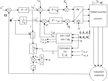
The model of the machine used for the control is given in the (
d
,
q
) by the following Equations (1): Ω − − − = Ω − Ω − − = Ω − + − = + + Ω − − − = + Ω + + + − = J f J C i i JL L p dt d T p i T L dt d p T i T L dt d V L T K K p i i i dt d V L K p T K i i i dt d r r sd rq sq rd r m rq r rd s sq r m rq rq s rd r sd r m rd sq s rq r rd sq sd s sq sd s rq r r sq s sd sd ) ( 2 3 1 ) ( ) ( 1 1 1 φ φ φ φ ω φ φ ω φ φ σ φ φ λ ω σ φ φ ω λ (1) With
=
−
+
=
=
−
=
=
s s s r s r S m r s m r r rR
L
T
T
T
L
L
L
K
L
L
L
R
L
T
;
1
1
1
;
:
1
;
2σ
σ
σ
λ
σ
σ
(2)
Ω
−
−
−
=
Ω
−
Ω
+
=
Ω
−
−
=
+
−
Ω
−
−
=
+
Ω
+
+
−
=
J
f
J
C
i
i
JL
L
p
dt
d
T
p
i
T
L
dt
d
p
Tr
i
T
L
dt
d
V
L
Tr
K
K
p
i
i
dt
d
V
L
K
p
T
K
i
i
dt
d
r r s r s r r m r r r s r r r r s r m r s s r r s s s s r r r s s)
(
2
3
1
1
1
1
α β β α β α β β β α α α β β α α β α β α α αφ
φ
φ
φ
φ
φ
φ
φ
σ
φ
φ
λ
σ
φ
φ
λ
(3)2.1. Vector Control
From the system of equation, the axis is aligned with the rotor flux vector (
φ
rd=
φ
r,
φ
q=
0
), the following Equation (4) system is obtained: Ω − − = Ω + = − = + Ω − − − = + + + − = f C C dt d J i T L T i T L dt d V L K p i i i dt d V L T K i i i dt d r e r sq r m s r r sd r m r sq s r sq sd s sq sd s r r sq s sd sd
φ
ω
ω
φ
φ
σ
φ
λ
ω
σ
φ
ω
λ
1 1 (4)To maintain the dynamic performance of such drives, estimating the time constant of machine and its adaptation with the programmed value at the rotor flux orientation block is required. An adaptation technique of this size has been proposed.
3. Estimator of the Time Constant of
Rotor
T
rTo develop the estimator, we take the model of IM in the stationary frame in the stationary reference. The dynamic model of induction motor supplied current is given in this benchmark by
dt
d
i
R
v
s s s s α α αφ
+
=
(5)dt
d
i
R
v
sβ=
s sβ+
φ
sβ (6)From which we can deduce the model of MAS powered, using the rotor flux as state variables. This model is given by:
[
α α]
βα
φ
ω
φ
φ
r r r s m r rr
L
i
L
R
dt
d
−
−
=
(7)[
β β]
αβ
φ
ω
φ
φ
r r r s m r r ri
L
L
R
dt
d
−
−
=
(8)The mathematical development of the estimator
T
r takes into account the equations of the stator voltages and the calculation of the termv
αsi
sβ−
v
sβi
sαWe have
α
β
β
α
α
β
β
α
φ
φ
ss s s s s s s
i
dt
d
i
dt
d
i
v
i
v
−
.
=
−
(9)Replace d r andd r
dt dt
β
α ϕ
ϕ
by their values given in (8), (9) the expression for the time constant () can be estimated by
[ ]
[ ]
{
1 2}
[ ]
3 4S
S
L
S
L
L
S
T
s m r r+
−
=
σ
(10) With α β β α s s ss
i
v
i
v
S
1=
α β β α s s s s
i
dt
di
i
dt
di
S
2=
−
)
(
3
ω
rφ
rβi
sφφ
rαi
sαS
=
+
β α α
β
φ
φ
ri
s ri
sS
4=
−
5
S
: Components deφ
αr,
φ
βrThe components
ϕ
rα andϕ
rβ are estimated by theequations (7) et (8) after integration.
β
s i
r
ω
m r
L L
L σ
+
-
+
u
1
e s Tr_
e s t Tr_
est rα _
φ
est
rβ _
φ
2
s
4
s
}
1
s
3
s
5
s
α
s v
β
s v
α
[image:3.595.198.412.79.356.2]s i
Figure 1. Estimator proposed scheme
3.1. Adaptation of the Rotor Time Constant
From measurable quantities of the machine (voltage, current, speed) we estimate
T
r using the equation (10). Once determined, we must ensure to maintain the time constant at the orientation block equal to the estimated value of which corresponds to the constant real time of the machine. [image:3.595.129.485.450.717.2]3.2. Simulation Results
Characteristic of MAS:
P 1.5kW, U 380V, N 1400tr / min,,= = = 3
s r s
R =4.850 , RΩ =3.805 , LΩ =274.10− H, .
3 3 2
r m
L =274.10− H, L =258.10− H, p=2, J=0.031kg.m
rd
s
m
N
f
r=
0
.
0014
.
.
/
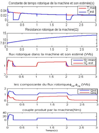
f =50Hz, I=6.5AWe will simulate the closed loop system without adaptation with a variation of the resistance in the first stage, then with adaptation
T
r. We tested the system behavior when the rotor resistance varies. The instants 1s and 2s thesystem is subjected to an application then removing a torque disturbance
C
r=
10
Nm
Note in Figure (3) the rotor flux increases with rotor resistance, so decoupling between flux and torque lost at times 1s and 2s and the estimated flux does not follow the actual flux of the machine the same for the estimated time constant
T
r does not follow realT
r.As there is no adaptation of the rotor time constantly, one can observe the effect of variation
T
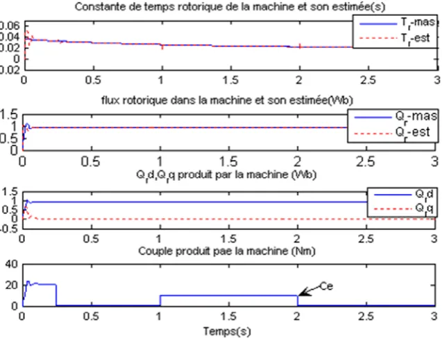
r on the dynamic response of flux and torque at the machine.It is clearly visible from Figure (4) that the curves that the adaptation constant function of the rotor time is
[image:4.595.140.470.272.712.2]accomplished despite the variation applied to the rotor resistance of the machine.
Figure. 4. Estimation results of the time constant and the rotor flux with adaptation
4. Conclusions
The results of this work on the training adjusted by conventional methods of indirect rotor flux orientation are obtained with improved performance of the control system studied is realized by the development of a blueprint indirect stronger whatever the variation of parameters with online correction of the variation of the time constant of rotor to maintain the decoupling block in perfect agreement with the actual conditions of engine operation.
REFERENCES
[1] C. Canudas de wit, "Control of asynchronous motors, 1," Modeling, vector control and DTC ", Paris, Hermès Science Publication, 2000.
[2] J.P Caron and J.P Hautier "Modeling and control of the asynchronous machine", Technical Edition 1995.
[3] B. Gabriel, "Vector control of the asynchronous machine in real-time environment MATLAB / Simulink", P.F.E 2001 in Industrial automation, Grenoble Regional Associated Center (C.U.E.F.A)
[4] T.V. Raumer, "Adaptive nonlinear control of asynchronous machine", PhD thesis INP of Grenoble, 1994.
[5] G. Sturtzer and E. Smigiel, "Modeling and control of three-phase motors", Ellipses Edition Marketing S.A, 2000.
[6] M. Abid, "Adaptation of the optimized control to the vector control of the inverter-powered asynchronous machine at MLI", PhD thesis, Sidi Bel Abbés University, 2005.
[7] D. Aguglia, "Identification of three-phase induction motor parameters for vector control", Université Laval québec, Canada, 2004.
[8] C. Canudas de Wit, "Control of asynchronous motors, and Modeling, Optimization, descriptive and observation", Paris, Hermès Science Publication, 2000.
[9] R. Krishanan, A.S. Bharadwaj, " Ariview of parameter sensitivity and adaptation indirect vector controlled induction moor drive systems " IEEE Transaction on Power Electronics, vol. 6, no. 4, pp.695-703, Oct.1991.
[10] H. Tambrat, "Robustness of minimal vector control", University of Batna, 2006
[11] N. Kabache, "Improvement of the performance of the control of the asynchronous cage motor and development of a universal estimator of its parameters using the RNA", University of Boumerdes., 2007.