2019 International Conference on Computer Intelligent Systems and Network Remote Control (CISNRC 2019) ISBN: 978-1-60595-651-0
An Efficient Method of Spread-Spectrum Logon for
Satellite Terminal in DVB Systems
Xueyi Liu, Xiaobo Ma, Zheng Yan and Qiao Yuan
ABSTRACT
In the satellite communication system, the antenna of the portable mobile terminal has a small aperture, and there is a risk of frequent online and offline in the case of movement and the logon process is cumbersome. Therefore, a CRMA-based spread-spectrum logon scheme is proposed. The structure of frame and superframe is designed, and the algorithm of modulation and demodulation is simulated and implemented, which is able to meet the requirement of application for mobile satellite communication terminal.
KEYWORDS
DVB, CRMA, Spread-Spectrum.
OVERVIEW
The satellite communication system proposed in this paper complies with the specifications of the DVB standards[1], [2], providing a standardised broadband interactivity connection. The forward link adopts the DVB-S2 protocol, and the return link adopts the DVB-RCS2 protocol to implement all-IP networking communication based on the satellite links. The system consists of one or more gateways and several terminals, forming a star-shaped topology network with a gateway as the core.
_________________________________________
Xueyi Liu, Xiaobo Ma, Zheng Yan, Qiao Yuan
DESCRIPTION OF LOGON PROCESS
BRIEF INTRODUCTION OF EXISTING LOGON SOLUTION
Applications
Intermediate layers
Link control Medium Access
control
Synchronization Modulation Channel coding
Freq.Range Filtering
Power
Higher Layers
Lower Layers
Figure 1. The protocol stack of DVB-RCS2.
A simple protocol stack model is used, consisting of the following layers: Physical layer, Data link layer, Intermediate layers and Applications layer. Figure 1 separates the lower layers from the higher layers in this simplified model, and identifies some of the key elements for the lower two layers.
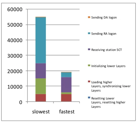
The terminal re-logon requires the following processes:
• Resetting Lower Layers, resetting higher Layers.
• Loading higher Layers, synchronizing lower Layers.
• Initializing lower Layers.
• Receiving station SCT.
• Sending RA logon.
0 10000 20000 30000 40000 50000 60000
slowest fastest
Sending DA logon
Sending RA logon
Receiving station SCT
Initializing lower Layers
Loading higher Layers, synchronizing lower Layers
[image:3.612.179.415.53.263.2]Resetting Lower Layers, resetting higher Layers
Figure 2. Logon time map (time unit: ms).
The Figure 2 shows that initializing lower layers, receiving station SCT and sending RA logon take a long time, making the terminal cannot logon quickly.
SPREAD-SPECTRUM LOGON SOLUTION
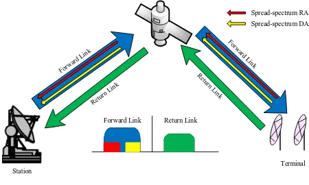
To ensure that the terminal can logon quickly, a CRMA-based spread-spectrum logon scheme is proposed. The specific scheme is described as follows:
• Resetting Lower Layers, resetting higher Layers.
• Sending a spread-spectrum RA logon in the frequency bands of forward link.
• Sending a spread-spectrum DA logon in the frequency bands of forward link.
The description of spread-spectrum logon scheme:
• Spread-spectrum RA logon can be sent at any time after Lower Layers reset
instead of sending in timeslots to reduce signaling interaction time.
• The collision probability of spread-spectrum RA logon is reduced, which
improves the success rate of RA logon.
• The frequency of the forward link is multiplexed.
• Due to the use of spread-spectrum communication, the signal-to-noise ratio of
the spread-spectrum logon is improved, and the interference to the forward signal is reduced.
• The spread-spectrum type follows DVB-RCS2 protocol, compatible with
existing systems.
• At the same time of the spread-spectrum logon, the original logon scheme is
Terminal Station Return Link Forward Link Spread-spectrum RA Spread-spectrum DA
Figure 3. The diagram of spread-spectrum logon.
ALGORITHM DESIGN ANDSIMULATION
FRAME STRUCTURE
(1)Frame Structure Design
The scheme is based on DVB-RCS2 protocol, and the new frame structure is
defined for CRMA. The frame structure of 2、4、8 times spread-spectrum is given in
[image:4.612.47.599.419.531.2]the DVB-RCS2 protocol, and the logon packet is 16 times spread-spectrum. The CRMA frame structure is 32 times spread-spectrum, and modified the pilot length and spacing, which reduces the complexity of capture, ensuring the system’s ability to resist frequency offset.
TABLE I. FRAME STRUCTURE OF CRMA.
ID Burst
Length (symbols) Spreading Factor Burst Length (chips) Payload length (bits) FEC efficien cy Payloa d length (symbo ls)
Mapping prea
mbe lengt h(chi ps) posta mbe length (chips) pilot period( chips) pilot block (chips) pilot sum (chip s) Pilot efficie-ncy informat ion efficienc y Equivalent rate increase multiple
50 1920 8 15360 800 1/2 1600 BPSK 1024 0 100 12 1536 83.33% 41.67% 1.75
51 1856 16 29696 800 1/2 1600 BPSK 1024 0 100 12 3072 86.21% 43.10% 2.61
52 1824 32 58368 800 1/2 1600 BPSK 1024 0 100 12 6144 87.72% 43.86% 4.32
53 1712 64 109568 800 1/2 1600 BPSK 1024 0 100 6 6144 93.46% 46.73% 4.57
54 1664 128 212992 800 1/2 1600 BPSK 2048 0 100 3 6144 96.15% 48.08% 4.70
(2) Superframe Structure Design
The superframe consists of the logon frame, traffic frame, and the superframe tail. The terminal transmits the data with superframe format. The specific superframe format is shown in the Figure 4. The superframe processing is divided into two phases: the logon phase and the data processing phase. The logon phase continuously transmits three logon packets. If a logon is successfully captured, the logon process is successful. In the data processing phase, the traffic packets are sequentially demodulated until the superframe tail is detected.
logon packet logon packet logon packet traffic packet traffic packet traffic packet superframe tail
ALGORITHM PERFORMANCE SIMULATION
(1) Algorithm Principle
The modulation and demodulation algorithm block diagram is shown in the Figure 5. The spread-spectrum baseband demodulation algorithm mainly includes digital down conversion, matched filtering, digital AGC, acquisition, timing synchronization, dispreading, carrier synchronization, decoding, CRC check, descrambling.
First, the down conversion filters is selected according to different chip rate, reducing the sample rate to 4 times of the chip rate. The AGC will adjust the data amplitude, and then the data is sent to the capture module. The data rate will be converted into signal chip rate by direct decimation, and then divided into two parts: pilot and payload, the pilot is sent to the carrier synchronization module for the frequency offset estimation and the initial phase offset estimation. After the descrambling and dispreading processes, the data rate of payload is reduced to signal symbol rate, frequency offset and phase offset compensation are performed, and then it is sent to the turbo decoding module, and the decoded data is subjected to CRC check.
Transmission
Receiver
the bit stream
pi/2-phase rotation Energy Dispersal Coding Baseband shape SRC
Mapping Spread Scrambling Insertion of PN
Modulation-spreading Sate
lli te C ha n ne l SRC Matched filtering Acquisition Timing synchronization pi/2-phase rotation
Descrambling Dispreading Carrier
synchronization Decoding Carrier
estimation
[image:5.612.186.414.288.402.2]Data
Figure 5. The diagram of modulation and demodulation algorithm.
(2) Algorithm Performance Simulation
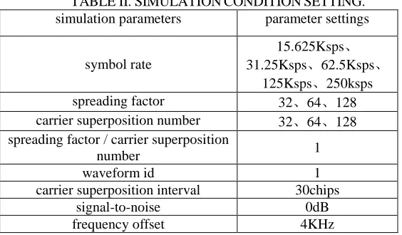
The performance of simulation for low symbol rate demodulation algorithm mainly includes two reference indicators: the capture probability and the error bit rate of hard-decision. The Table III gives the capture performance of 32 times spread-spectrum. The Table IV, Table V and Table VI give the error bit rate of hard-decision for each symbol rate in the case of 32 times, 64times, 128 times spread-spectrum respectively. The specific simulation conditions are set as shown in the Table II.
TABLE II. SIMULATION CONDITION SETTING. simulation parameters parameter settings
symbol rate
15.625Ksps、 31.25Ksps、62.5Ksps、
125Ksps、250ksps
spreading factor 32、64、128
carrier superposition number 32、64、128 spreading factor / carrier superposition
number 1
waveform id 1
carrier superposition interval 30chips
signal-to-noise 0dB
[image:5.612.158.440.555.720.2]TABLE III. THE PERFORMANCE OF SPREAD-SPECTRUM CAPTURE.
symbol rate (Ksps) Spreading factor chip rate Capture length capture probability of failure
250 32 8M 1024 2.41E-4
TABLE IV. THE PERFORMANCE OF SPREAD-SPECTRUM CAPTURE FOR 32 TIMES. symbol rate (Ksps) Carrier superposition
number hard-decision bit error rate
15.625 32 9.16E-02
31.25 32 8.83E-02
62.5 32 9.11E-02
125 32 1.15E-01
250 32 1.13E-01
TABLE V. THE PERFORMANCE OF SPREAD-SPECTRUM CAPTURE FOR 64 TIMES. symbol rate (Ksps) carrier superposition
number hard-decision bit error rate
15.625 64 8.87E-02
31.25 64 8.09E-02
62.5 64 8.39E-02
[image:6.612.120.490.363.413.2]125 64 1.10E-01
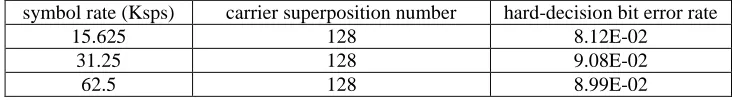
TABLE VI. THE PERFORMANCE OF SPREAD-SPECTRUM CAPTURE FOR 128 TIMES.
The Table III, Table IV, Table V and Table VI show that both the acquisition probability performance and the hard-decision performance match the system requirements.
The calculation process of the throughput rate of the CRMA system is given in the study[3]. The throughput is mainly affected by the collision and demodulation errors. The gain of the spread-spectrum is given as Gp, the equivalent signal-to-noise ratio of the superimposed signal is as shown in (1).
p b
0
G E
N
K(1)
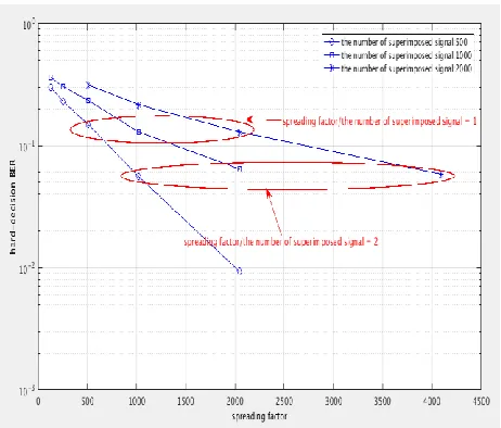
Based on the equivalent signal-to-noise ratio, the demodulation performance of CRMA can be analyzed. Reference to the equivalent formula, the scheme uses the spread-spectrum gain to cancel the performance loss caused by multi-channel interference, that is, the spreading factor is the same as the number of superimposed signal, and the demodulation performance is also consistent.
When the ratio of the spreading factor to the number of superimposed signal is 1, the boost performance gain of the spread-spectrum cancels the interference introduced by the multi-channel superposition, and the hard-decision bit error rate is about 1.30e-1. When the ratio of the spreading factor to the number of superimposed signal is 2, the hard-decision bit error rate is about 6.00e-2, as shown in Figure 6.
symbol rate (Ksps) carrier superposition number hard-decision bit error rate
15.625 128 8.12E-02
31.25 128 9.08E-02
Figure 6. The relationship between spreading factor and hard-decision bit error rate.
CONCLUSION
In this paper, the spread-spectrum logon method for satellite terminal is designed and implemented. The modulator of terminal is implemented by FPGA, and the demodulator of station is implemented by FPGA and DSP together (the DSP is mainly responsible for frequency offset estimation, frequency offset compensation, signal-to-noise ratio estimation, etc.). The bandwidth of demodulation is 8MHz which can meet the needs of 32 terminals for simultaneous transmission. Compared with the common logon method, the logon time is shortened by more than 60%, and the resource is increased by about 20%, which satisfies the application requirements of mobile satellite communication.
REFERENCES
1. ETSI EN 301 545-2, Second Generation DVB Interactive Satellite System (DVB-RCS2); Part 2: Lower Layers for Satellite standard, 04.2014.
2. ETSI TR 101 545-4, Second Generation DVB Interactive Satellite System (DVB-RCS2); Part 4: Guidelines for Implementation and Use of EN 301 545-204.2014.