© 2016, IRJET | Impact Factor value: 4.45 | ISO 9001:2008 Certified Journal
| Page 2891
INCREASING C.O.P OF A REFRIGERATOR USING
DIFFUSER
Ramesh.S
1,Prakash.E
2,Sasikumar.R
3.R,Shajakhan.B
4Jeevanantham.S
5(Assistant professor/Mechanical, Gnanamani college of Technology)
Gnanamani college of technology, Namakkal.
---***---Abstract -The goal of this project is to provide a
proof of concept, that an efficiency of a
refrigerator is increased by installing the
Diffuser between the condenser and the
Evaporator. In this space we are looking at
opportunities to conserve energy by improving a
product or a process, therefore, reducing its
energy consumption. This included validating
that the thermodynamic cycle is feasible and
fabricating of a prototype, driven by compressed
air, to acquire data on the design’s mechanical
functionality. With this system, an adequate
cooling effect is produced with minimal
electrical energy input. Markets such as produce
transportation,
biomedical
refrigeration,
commercial and residential air conditioning, and
even the familiar drink cooler could benefit from
this technology. To turn this idea into a
marketable, economically feasible, mechanical
device would forever change the way we use our
energy. The uniqueness of this project is, this
consumes less energy compared to the
conventional refrigerators. So, embracing an
energy efficient lifestyle today will help you get a
better life tomorrow. So let us slow down the
demand for energy and give a better future for
our coming.
KEYWORDS: Refrigerator, Diffuser, Pressure deviation, Increasing efficiency, Economical.
1. INTRODUCTION
1.1. Refrigeration
Refrigeration is the 'artificial' extraction of heat from a substance in order to lower its temperature to below that of its surroundings. Primarily, heat is extracted from fluids such as air and many liquids, but ultimately from any substance. In order to extract heat a region of 'cold' has to be created. A number of effects can be used:-
1. The Peltier effect (reverse of thermocouples); 2. Endothermic chemical reactions;
3. Induced vaporization of a liquid.
In thermodynamic terms a refrigerator is a reversed heat engine. I.e. heat may transfer from a cold reservoir to a hot reservoir by expending work. Modern refrigerators operate by the same reverse-heat-engine principle. Whereas a heat engine converts heat (from a high-temperature area) to work, a refrigerator converts work to heat. Modern refrigerators use substances other than air as the coolant; the coolant substance changes from gas to liquid as it goes from higher to lower temperature. This change from gas to liquid is a phase transition, and the energy released upon this transition is mainly dependent on the intermolecular interactions of the substance. Refrigeration maintains the temperature of the heat source below that of its surroundings while transfer- ring the extracted heat and any required energy input, to a heat sink, atmospheric air, or surface water. A refrigeration system is a combination of components and equipment connected in a sequential order to produce the refrigeration effect.
2. PROPOSED SYSTEM
Refrigeration systems refer to the different physical components that make up the total refrigeration unit. The different stages in the refrigeration cycle are undergone in these physical systems. These systems consist of an evaporator, a condenser, a compressor and an expansion valve. The evaporator is the space that needs to be cooled by the refrigerant; the compressor compresses the refrigerant from the low pressure of the evaporator to the pressure at the condenser. The heat gained by the refrigerant is rejected at the condenser and the high pressure refrigerant is expanded into the low pressure evaporator by the expansion valve. This is a very general representation of the various units in a refrigeration system. The refrigeration systems vary according to the purpose and the type of refrigerant used.
2.1. Description of Equipments:
Compressor,
Condenser,
Expansion devices,
© 2016, IRJET | Impact Factor value: 4.45 | ISO 9001:2008 Certified Journal
| Page 2892
2.1.1. Compressor:
A compressor that is a component of a vapor-compression refrigerating machine and is used to draw the refrigerant vapor from the evaporator and deliver it to the condenser. One of the most important characteristics of a refrigerating compressor is the refrigerating capacity of the refrigerating system, which, for a given refrigerant and under given temperature conditions, is proportional to the volumetric refrigerating capacity.
Depending on the refrigerants employed, the required volumetric refrigerating capacity, and certain other conditions, the following types of compressors are used in refrigerating engineering: reciprocating, rotary, screw, and centrifugal. Refrigerating compressors are similar to air and gas compressors in the principle of operation.
However, they have a number of features that are associated with the operating conditions of refrigerating machines and with the thermodynamic, physical, and chemical properties of the vapor of the refrigerant used. For example, refrigerating compressors typically operate with superheated vapor. Certain requirements are imposed on refrigerating compressors. These include the feasibility of single-stage compression at substantially higher pressure discharge-to-suction ratios than in air compressors, that is, at pressure ratios of up to 10–12 or—in certain specially designed compressors—up to 25–30; the possibility of controlling the volumetric refrigerating capacity; the reduction of unbalanced forces, overall dimensions, and weight; and low noise levels, especially for the refrigerating compressors used in domestic refrigerators and
air-conditioning systems
Fig -1: Compressor
compressors. Hermetically sealed compressors, which may be of the reciprocating or rotary type, are used when relatively low (up to several kilowatts) refrigerating capacities are required, for example, in domestic refrigerators and air conditioners and in commercial refrigerating equipment.
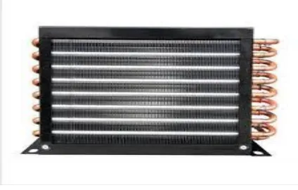
2.1.2 Condenser:
In systems involving heat transfer, a condenser is a device or unit used to condense a substance from its gaseous to its liquid state, by cooling it. In so doing, the latent heat is given up by the substance, and will transfer to the condenser coolant. Condensers are typically heat exchangers which have various designs and come in many sizes ranging from rather small (hand-held) to very large industrial-scale units used in plant processes.
For example, a refrigerator uses a condenser to get rid of heat extracted from the interior of the unit to the outside air. Condensers are used in air conditioning, industrial chemical processes such as distillation, steam power plants and other heat-exchange systems. Use of cooling water or surrounding air as the coolant is common in many condensers.
A typical configuration of such a condenser unit is as follows: The heat exchanger section wraps around the sides of the unit with the compressor inside. In this heat exchanger section, the refrigerant goes through multiple tube passes, which are surrounded by heat transfer fins through which cooling air can move from outside to inside the unit. There is a motorized fan inside the condenser unit near the top, which is covered by some grating to keep any objects from accidentally falling inside on the fan. The fan is used to blow the outside cooling air in through the heat exchange section at the sides and out the top through the grating. These condenser units are located on the outside of the building they are trying to cool, with tubing between the unit and building, one for vapor refrigerant entering and another for liquid refrigerant leaving the unit.
2.1.2.1 Air cooled condensers:
© 2016, IRJET | Impact Factor value: 4.45 | ISO 9001:2008 Certified Journal
| Page 2893
Fig -2:Air cooled condensers
These types of condensers eject heat to the outdoors and are simple to install. Most common uses for this condenser are domestic refrigerators, upright freezers and in residential packaged air conditioning units. A great feature of the air cooled condenser is they are very easy to clean. Since dirt can cause serious issues with the condensers performance, it is highly recommended that these be kept clear of dirt.
2.1.3. Expansion devices:
Thermostatic expansion valve or TEV is one of the most commonly used throttling devices in the refrigerator and air conditioning systems. The thermostatic expansion valve is the automatic valve that maintains proper flow of the refrigerant in the evaporator as per the load inside the evaporator. If the load inside the evaporator is higher it allows the increase in flow of the refrigerant and when the load reduces it allows the reduction in the flow of the refrigerant. This leads to highly efficient working of the compressor and the whole refrigeration and the air conditioning plant. The thermostatic expansion valve also prevents the flooding of the refrigerant to the compressor ensuring that the plant would run safely without any risk of breakage of the compressor due to compression of the liquid. The thermostatic expansion valve does not controls the temperature inside the evaporator and it does not vary the temperature inside the evaporator as its name may suggest. Beside the capillary tube, the thermostatic expansion valve is used widely in the refrigeration and air conditioning systems. While the capillary tube is used in the small domestic systems, the thermostatic expansion valve is used in the systems of higher capacities. It is commonly used in the industrial refrigeration plants, high capacity split air conditioners, packaged air conditioners, central air conditioners and many other systems.
Fig -3:
Expansion devices
2.1.3.1. Functions of expansion valve:
Reduce the pressure of the refrigerant,
Allow the flow of the refrigerant as per the requirements.
2.1.4. Throttling device:
Capillary tube is one of the most commonly used throttling devices in the refrigeration and the air conditioning systems. The capillary tube is a copper tube of very small internal diameter. It is of very long length and it is coiled to several turns so that it would occupy less space. The internal diameter of the capillary tube used for the refrigeration and air conditioning applications varies from 0.5 to 2.28 mm (0.020 to 0.09 inches). Capillary tube used as the throttling device in the domestic refrigerators, deep freezers, water coolers and air conditioners.
Fig -4:
Throttling device
[image:3.595.51.263.103.238.2] [image:3.595.343.533.548.691.2]© 2016, IRJET | Impact Factor value: 4.45 | ISO 9001:2008 Certified Journal
| Page 2894
diameter of the capillary and the length of the capillary.Smaller is the diameter and more is the length of the capillary more is the drop in pressure of the refrigerant as it passes through it. In the normal working conditions of the refrigeration plant there is drop in pressure of the refrigerant across the capillary but when the plant stops the refrigerant pressure across the two sides of the capillary equalize. Due to this reason when the compressor restarts there won’t be much load on it.
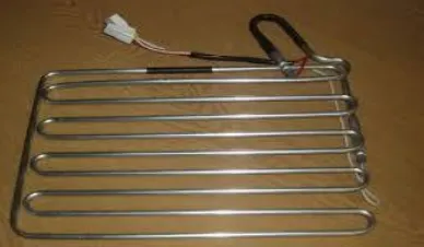
2.1.5. Evaporator:
The evaporator is a bank or coil of tubing placed inside the refrigeration space. The refrigerant is at a low-pressure and low-temperature liquid, as it enters the evaporator.
As the refrigerant circulates through the evaporator tubes, it absorbs its heat of vaporization from the surrounding space and substances. The absorption of this heat causes the refrigerant to boil. As the temperature of the surrounding space (and contents) is lowered, the liquid refrigerant gradually changes to a vapor. The refrigerant vapor then passes into the suction line by the action of the compressor. Most evaporators are made of steel, copper, brass, stainless steel, aluminum, or almost any other kind of rolled metal that resists the corrosion of refrigerants and the chemical action of the foods.
Fig -5:
Evaporator
Evaporators are mainly of two types—dry or flooded. The inside of a dry evaporator refrigerant is fed to the coils only as fast as necessary to maintain the temperature wanted. The coil is always filled with a mixture of liquid and vapor refrigerant. At the inlet side of the coil, there is mostly liquid; the refrigerant flows through the coil (as required); it is vaporized until, at the end, there is nothing but vapor. In a flooded evaporator, the evaporator is always filled with liquid refrigerant. A float maintains liquid refrigerant at a constant level. As fast as the liquid refrigerant evaporates, the float admits more liquid, and, as a result, the entire inside of the
evaporation, either direct expanding or indirect expanding. In the direct-expanding evaporator, heat is transferred directly from the refrigerating space through the tubes and absorbed by the refrigerant. In the indirect-expanding evaporator, the refrigerant in the evaporator is used to cool some secondary medium, other than air. This secondary medium or refrigerant maintains the desired temperature of the space. Usually brine, a solution of calcium chloride is used as the secondary refrigerant.
2.1.6. Diffuser:
A duct which decreases the velocity of a fluid and causes a corresponding increase in pressure is called a diffuser. An investigation has been conducted in the Cleveland 18- by 18-inch supersonic tunnel at a Mach number of 1.85 and angles of attack from 0 deg to 5 deg to determine optimum design configurations for a convergent-divergent type of supersonic diffuser with a subsonic diffuser of 5 deg included divergence angle. Total pressure recoveries in excess of theoretical recovery across a normal shock at a free-stream Mach number of 1.85 wore obtained with several configurations. The highest recovery for configurations without a cylindrical throat section was obtained with an inlet having an included convergence angle of 20 deg. Insertion of a 2-inch throat section between a 10 deg included angle inlet and the subsonic diffuser stabilized the shock inside the diffuser and resulted in recoveries as high as 0.838 free-stream total pressure at an angle of attack of 0 deg, corresponding to recovery of 92.4 percent of the kinetic energy of the free air stream. Use of the throat section also lessened the reduction in recovery of all configurations due to angle of attack.
[image:4.595.61.255.468.581.2] [image:4.595.316.526.543.712.2]© 2016, IRJET | Impact Factor value: 4.45 | ISO 9001:2008 Certified Journal
| Page 2895
2.1.7. Refrigerant:
A refrigerant is a substance or mixture, usually a fluid, used in a heat pump and refrigeration cycle. In most cycles it undergoes phase transitions from a liquid to a gas and back again. Many working fluids have been used for such purposes. Fluorocarbons, especially chlorofluorocarbons, became commonplace in the 20th century, but they are being phased out because of their ozone depletion effects. Other common refrigerants used in various applications are ammonia, sulfur dioxide, and non-halogenated hydrocarbons such as propane. The ideal refrigerant would have favorable thermodynamic properties, be noncorrosive to mechanical components, and be safe, including free from toxicity and flammability. It would not cause ozone depletion or climate change. Since different fluids have the desired traits in different degree, choice is a matter of trade-off. The desired thermodynamic properties are a boiling point somewhat below the target temperature, a high heat of vaporization, a moderate density in liquid form, a relatively high density in gaseous form, and a high critical temperature. Since boiling point and gas density are affected by pressure, refrigerants may be made more suitable for a particular application by choice of operating pressures.
2.1.8. Freon:
Freon is a registered trademark of The Chemours Company, which it uses for a number of halocarbon products. They are stable, nonflammable, moderately toxic gases or liquids which have typically been used as refrigerants and as aerosol propellants
2.1.8.1.
Physical Properties:
Chemical formula CCl2F2
Molecular mass 120.91
Boiling point -29.75deg Celsius Critical temperature 111.97 deg Celsius Critical pressure 4136kpa
Critical density 565.0 kg/m3 Critical volume 0.0018 m3/kg
Table -1:
Physical Properties for R12
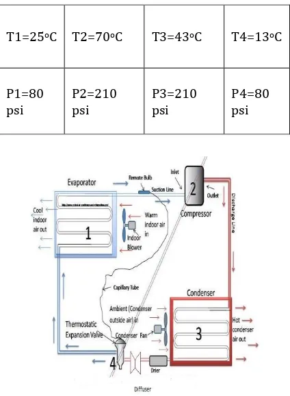
2.1.9. Schematic diagram:
Fig -7:
Schematic diagram
2.1.10. Working principle:
Referring to the illustration above, beginning the cycle at the evaporator inlet, the low-pressure liquid expands, absorbs heat, and evaporates, changing to a low-pressure gas at the evaporator outlet. The pumps this gas from the evaporator through the accumulator increases its pressure, and discharges the high-pressure gas to the condenser. In the condenser, heat is removed from the gas, which then condenses and becomes a high-pressure liquid. In some systems, this high-high-pressure liquid drains from the condenser into a liquid storage or receiver tank. On other systems, both the receiver and the liquid line valve are omitted. Between the condenser and the evaporator and before an expansion device, a small Diffuser is located. Here, the pressure of the fluid gets increased and temperature is maintained in average manner. Therefore flow of refrigerant into the evaporator is controlled by the pressure differential across the expansion device or, in the case of a thermal expansion valve, by the degree of superheat of the suction gas. As the high-pressure liquid refrigerant enters the evaporator; it is subjected to a much lower pressure due to the suction of the compressor and the pressure drop across the expansion device. Thus, the refrigerant tends to expand and evaporate. In order to evaporate, the liquid must absorb heat from the air
T1=25oC T2=70oC T3=43oC T4=13oC
P1=80
[image:5.595.317.529.116.405.2]© 2016, IRJET | Impact Factor value: 4.45 | ISO 9001:2008 Certified Journal
| Page 2896
the thermostat or cold control will break the electricalcircuit to the compressor motor and stop the compressor. As the temperature of the air through the evaporator rises, the thermostat or cold control remakes the electrical circuit. The compressor starts, and the cycle continues.
2.1.11. Calculation of C.O.P:
2.1.11.1. C.O.P for
Existing system
:-T1= Temperature after Evaporation
T2= Temperature after Compression
T3= Temperature after Condensation
T4= Temperature after Expansion
1 psi = 0.067 bar
P1= P4 = 80*0.067 = 5.36 bar
P2= P3 = 210*0.067=14.07 bar
Use gas R-12 PH chart and Find out the
h1=192 KJ / kg
h3= h4 =60 KJ / kg
Theoretical C.O.P= (h1-h3) / (h2-h1)
= (192-60) / (230-192)
= 3.47
2.1.11.2. C.O.P for
Proposed system
:-1 psi = 0.067 bar
P1= P4 = 80*0.067 = 5.36 bar
P2= P3 = 230*0.067=15.41 bar
Use gas R-12 PH chart and Find out the
h1=209 KJ / kg
h2=242.5 KJ / kg
h3= h4 =80 KJ / kg
Theoretical C.O.P= (h1-h3) / (h2-h1)
= (209-80) / (242.5-209)
= 3.85
2.1.12. Analysis reports:
The below diagram shows the result of increased pressure in the capillary tube by fixing diffuser between the condenser and expansion valve:
T1=27oC T2=80oC T3=45oC T4=13o C
© 2016, IRJET | Impact Factor value: 4.45 | ISO 9001:2008 Certified Journal
| Page 2897
Fig -8: Diffuser Design DiagramFig -9: Diffuser mesh analysis
[image:7.595.38.551.46.802.2]Fig -10: Diffuser pressure analysis
Fig -11: Diffuser temperature analysis
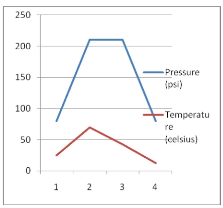
2.1.13. Pressure Deviation in the system by
fixing Diffuser:
The below diagram shows the result of Existing system and Proposed system pressure deviation in the capillary tube by fixing the diffuser between the condenser and expansion valve. The pressure and temperature is used to plotted on the graph.
2.1.13.1. Existing system:
[image:7.595.50.267.327.736.2] [image:7.595.313.535.489.696.2]© 2016, IRJET | Impact Factor value: 4.45 | ISO 9001:2008 Certified Journal
| Page 2898
Chart -2: Proposed system2.1.14. Merits:
Simple construction and efficient.
Low power consumption.
Simple Easy to operate.
Maintenance cost low.
High efficiency.
2.1.15. Applications:
It is used to preserve food items,fruits,vegetables fresh for several days from being spoilt,
Gas Turbine Air Inlet Cooling,
Reflux chillers
Vent gas /solvent recovery chillers
Brine / Water chillers
It can be also used for preservation of dairy products, Blood plasma and antibiotics are manufactured using a method called freeze drying,
It can be used to “preserve fishes and meat” in ship containers for several days during travel in the sea
The project done by us will make an impressing mark in the field of Refrigeration .This project have also reduced the cost involved in the concern. The project has been designed to attain the cooling effect quicker than the prescribed time. Compared to other conventional refrigerators our project is very compact and able to save energy and it is also cost effective. So our project will play a major role in the field of engineering.
REFERENCES:
Rajput R.K., “Textbook of Thermal Engineering” and “Refrigeration books”
Khurmi R.S., Gupta J.K., “A Textbook of Refrigeration and Air Conditioning”
“Refrigeration and Air Conditioning” by Ramesh Chandra Aroara
“Thermal Engineering” book by Dr.G.K.Vijayaraghavan
“Engineering thermodynamics” by Dr.G.K.Vijayaraghavan & Sundaravalli
Thermodynamic approach for Refrigeration and Air Conditioning by khandawala.
Jordan Journal of Free Cooling Technique in Air Refrigeration systems,
“Refrigeration and Air Conditioning with reduced Environmental impact “article on International Refrigeration and Air conditioning conference.
“Experimental development of an intelligent refrigeration system” on International journal of Refrigeration.
Thermodynamic properties of Freon-12 Refrigerant from Wikipedia
“Environmental management of refrigeration
equipment” report on WHO
© 2016, IRJET | Impact Factor value: 4.45 | ISO 9001:2008 Certified Journal
| Page 2899
Text book of refrigeration and air conditioning by Domkundwar.
www.wikipedia.com/refrigeration