© 2016, IRJET | Impact Factor value: 4.45 | ISO 9001:2008 Certified Journal
| Page 1253
Designing a suitable robotic arm for loading and unloading of material
on lathe machine using workspace simulation software
Milind R. Shinde
1, V. N. Bhaiswar
2, B. G. Achmare
31
Student of MTECH CAD/CAM, Department of Mechanical Engineering, GHRCE Nagpur, Maharashtra, India
2
Associate Professor, Department of Mechanical Engineering, GHRCE Nagpur, Maharashtra, India
3
Deputy General Manager, JSW ISPAT Steel Limited, Nagpur, Maharashtra, India
---***---Abstract -
Normally the loading and unloading ofwork piece on lathe machine is done with manual interface. Our aim is to make it automatic and fast for better accuracy and improved performance. Robotic work cell simulation is a modeling-based problem solving approach developed for the design, analysis and offline programming of robotic work cell. Robotic simulation covers the visualization of how the robot moves through its environment. This project deals with designing the robotic arm which is to be used for unload and load the work piece on lathe machine. The CAD model of robotic arm is made using CATIA V5 software and its simulation performed on Workspace Simulation Software. This will increase the total productivity of machine where there is continuous operation and complete machine utilization. Use of Workspace LT software for designing the robotic components is very popular.
Key Words: Robotic arm, simulation, Workspace LT,
etc…
1. INTRODUCTION
Material handling is one of the tedious tasks in industry now a day. In the country like India, many industries prefer manually operated material handling. This is very time consuming and due to this production rate also decreases. Lathe machine is common machine tool found in almost all industries and engineering institutes for processing the cylindrical work piece. The operation like turning, drilling, boring, chamfering, knurling etc. can be performed on it.
Loading and unloading of work piece on lathe machine is done manually, this may lead to less production in time. We can say that there are two times, referring to machine, one is machine utilization time and second is machine un-utilization time. In first case, the machine is in running condition and in second case
machine is in rest condition. If we consider 8 hours of shift per day then in that only 6.30 hours machine is in running condition and in rest 1.30 hours it is in rest. The rest time includes, operator or person working on machine time like going for lunch, toilet, talking with others etc. If we utilize this time for running machine continuously then there will be no delay in production.
The automatic material loading and unloading equipment is needed to run machine continuously. Robotic arm arrangement is best option for doing this. By implementing this robotic arm on lathe machine then whole operation can be automated, single person can then handle 4 to 5 machine at a time. A robotic arm can be any of a number of mechanical, programmable devices that are designed to manipulate objects in a way that is similar to the human arm. The robotic arm is one of the most useful pieces of technology to be introduced in the 20th century, and quickly became a cornerstone in many areas of manufacturing. It can be used for many different jobs and functions that may be too tedious, difficult or dangerous for a human to do. You might first think of the automobile industry when thinking about robotic arms, but they can be used for many other useful tasks besides welding and painting auto parts.
While working in a fashion similar to the human arm, robot arms can still have a much wider range of motion since their design can be purely up to the imagination of their creator. The joint that connects the segments of a robotic arm, for example, can rotate as well as moving like a hinge. The end of the robotic arm designed to actually do the work that it was designed for is known as the end effectors, and can be designed for practically any task, for example gripping like a hand, painting, tightening screws and more. These robots can be fixed in one place, for example along an assembly line, or they can be mobile so they can be transported to do a variety of tasks in different places.
© 2016, IRJET | Impact Factor value: 4.45 | ISO 9001:2008 Certified Journal
| Page 1254
to make a robot and simulate it. The Workspace 5 isdesigned for industry use, in that software industrial professional designed their robots as per the machine considerations and simulate it to see the result.
2. LITERATURE SURVEY
This paper deals with designing a Robotic arm in the national Science Foundation Engineering Senior Design Projects for the person having some disability in arms and legs. Its name was ‘Clutching and Gripping Device’ developed by Arizona State University [1]. This device have a motorized scooter, for mobility and provision of an assistive device to grasp and collect items or object which are out of his/her reach.
The similar kind of project was made by the University of Massachusetts named as ‘Assistive Reach Mechanism’. This device was having capacity to reach objects up to four feet from it and lifts five pounds of load. The device had the ability to pick up objects which are very small in size like needle or very large like a can with gripping claw.
[2]Multi-DOF Robotic Assembly for Press Shops is the another example of robotic arm. This project deals with the design, fabrication and control or monitoring of a robotic arm used for loading and unloading the metal sheets into a press. It consist of two stepper motors, out of which one control the motion of the arm and other the orientation of the wrist. The proximity sensors are placed at suitable location to control robot motion on machine press itself. Microcontrollers are used for controlling motor rotation.
A robotic arm operating on haptic technology having four degrees of freedom is unique concept on which these expert perform their research. It is designed for picking up certain object of specific weight and placing at desired location is presented in this project [3]. The remote controller, controls the movement of robotic arm, The robotic arm is made of Polycarbonate material. The joints having certain angle of rotation are fitted with potentiometer. The microcontroller named Arduino duemlanove consist of ATemega- 328 as a processor is used to read potentiometer input signal in electrical form and convert it into digital pulse form (PWM), which drives the servomotors or the arm.
The new concept of designing a robotic arm with additive technology is explained in this paper. There objective was to design and built a customized, lightweight and low cost robot, capable to fulfil many industrial working tasks such as palletizing mobile telephone covers[4]. Solidworks software were used to designing and optimizing the robotic structure. Different parts of robot are with additive manufacturing technology-
powder material PA 2200. For solving the forward and inverse kinematics of the robot, the Software tool SimMechanics from MathWorks was used.
Articulated robotic arm is used for handling and separating waste in waste management facility. This project focuses on thorough analysis on the design project of robotic arm for waste management application[5]. The CAD software, SolidWorks is used to model the detail design of the robotic arm, and to simulate the motion of the device.
This paper proposes a study on the workspace of the guiding device mechanism of a parallel topology robot. The kinematical scheme and the geometrical model of the guiding device mechanism of the parallel topology robot are presented[6]. The lengths of binary links between the platforms determine the shape and the volume of the parallel robot’s workspace; different boundaries of the workspace are presented. Thus, variation of the workspace in both volume andshape is studied, depending on the binary link lengths, using for modeling and simulation SolidWorks software.
Development of versatile robotic hand just like artificial arm or humanoid robot is need of today. In this paper, omni-directional bending mechanism called "double-screw-drive mechanism" was applied to drive a robotic hand.[7] Robotic hand having three fingers as gripping part was built, and experimentation was carried out, in which each finger was controlled so as to track the elliptical orbit. In actual operation this humanoid robot can able to open the PET bottle cap with its three fingers very easily and can tight it again.
The robotic arm driven by pneumatic actuator for material handling was developed by this team.[8] It consist of pneumatic hand and pneumatic wrist. The hand looks like human hand and able to grasp objects that have different shapes and mechanical characteristics. In this research, experimental models of the drive system of the pneumatic robot wrist have been constructed. With this model, the control systems were designed through simulations.
© 2016, IRJET | Impact Factor value: 4.45 | ISO 9001:2008 Certified Journal
| Page 1255
3. METHODOLOGY
For designing a complete new robotic arm, the points like machine space, type of work piece to be load, robotic configuration and no. of links should be considered. Most of the machine loading and unloading robots are fixed to foundation, if there is failure in operation then it is very difficult to move robot to another place. For solving this difficulty we have designed a table on which the robot will be mounted, and this table will be attached with machine bed.
[image:3.595.312.555.99.233.2]3.1 Design of table
Fig- 1: CAD drawing of table
This CAD model of table is designed in CATIA V5 software. There is provision of clamping to machine bed. The four wheels are provided to move the robot from operation place to the repair station in failure condition. The circular robotic base is shown on it. The corners of table is chamfered for safety purpose.
3.2 Robot Configuration
Robotic configuration gives us the exact idea of work volume and space of operation of robot. As per the joint and link movements, the configurations are of different types. Following are the basic configurations used for designing robots.
A.
Polar configuration
The robot has rotary base and pivot that can be used to raise and lower a telescoping arm.
Fig-2: Polar configuration
B.
Cylindrical configuration
[image:3.595.38.288.268.406.2]The arm consist of several orthogonal slides which allow the arm to be moved up or down and in and out with respect to body.
Fig-3: Cylindrical configuration
C.
Jointed arm configuration
The arm consists of several straight members connected by joints which are analogous to human shoulder, elbow and wrist.
Fig-4: Jointed arm configuration
[image:3.595.309.558.345.481.2] [image:3.595.308.553.590.726.2]© 2016, IRJET | Impact Factor value: 4.45 | ISO 9001:2008 Certified Journal
| Page 1256
The three slides are parallel to x, y and z axes. Byappropriate movements of these slides, the robot is capable of moving its arm to any point.
Fig-5: Cartesian configuration
For our concept we used combination of polar and jointed arm configurations. The proposed robotic arm will have seven axis motion. The wrist consist of two gripper with four fingers.
3.3 Lathe machine and work piece
As the robotic arm will be programmed for performing specific operation repeatedly, therefore we have considered drive shaft coupling finger as our loading and unloading material. The lathe machine used in JSW ISPAT Steel Industry is NH26 HMT Lathe. This lathe machine is used to machine the work piece from 20mm to 575mm diameter. It consist of 4 jaw chuck for giving better stability during operation for large diameter work piece.
Fig-6: NH26 HMT Lathe
Fig-7: Drive shaft coupling finger (as a work piece)
Drive shaft coupling finger specifications:- Length (before processing)- 55mm
Length (after processing)- 50mm Diameter (before processing)- 30mm Diameter (after processing)- 25mm Circular thread- M24*3 pitch Chamfer angle- 45 ͦ
Mass- 192gm Material- Mild steel
The company produces different types of products with different specifications and for loading and unloading of this products through robotic arm we have to develop different programs.
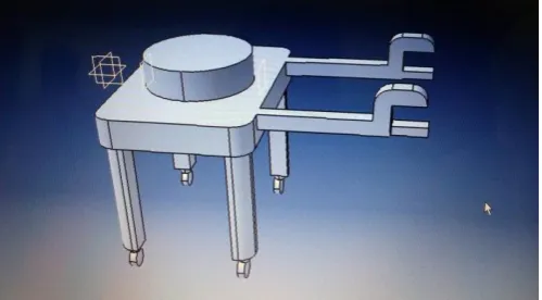
3.4 Gripper design
Designing of gripper for robotic arm is very difficult task. In this case for loading and unloading we have designed a very special kind of gripper. Four finger gripper is attached with the wrist. Two gripper is provided due to which the loading and unloading of work piece can be takes place at a time.
The wrist have three degrees of freedom and three axis rotation. The wrist can able to grasp the different diameter objects. The four fingers on both side provide perfect handling of objects during loading and unloading operation
.
© 2016, IRJET | Impact Factor value: 4.45 | ISO 9001:2008 Certified Journal
| Page 1257
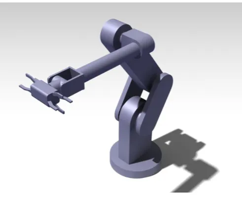
Fig-8: Gripper CAD drawing3.5 Proposed design
Fig-8: CAD model of robotic arm
This proposed design consist of robotic base at the bottom and whole assembly is build over it. The robotic base have complete 360 degree rotation during operation. This robotic arm have 7-axis rotation about various links.
The robotic arm would be driven by electric DC motor drives, as it is used for low weight loading operation. This whole assembly then mounted on the movable table and this table is then attached with the lathe machine. The actual work cell would consist of three table. One is for robotic arm, second for holding unfinished work piece and third one is for the finished work piece.
The robotic arm will collect the work piece from unfinished work table with one of the gripper and load it inside the chuck of lathe machine, when operation is over. At the same time the other gripper will take out the work piece from chuck and now the wrist will rotate 180ͦ angle and the gripper with unfinished work piece will load that
in to the chuck. Finally the robotic arm will place that finish work piece on finished work piece containing table. From this, we understand that, at the same time the robotic arm will handle both finished and unfinished work piece. Due to which time required for loading and unloading would be reduced.
After referring so many designs of robotic arm, we developed this unique, simple and multipurpose design. In further study we will consider the robot kinematics, sensor technology and various motions.
3.6 Drive system
Drive system is the actuating system of robot. According to the load to be lifted or operated we use different drive system. There are three types of drive system used in robotics, these are,
1. Hydraulic drive 2. Pneumatic drive 3. Electrical drive
Hydraulic drive systems are completely meant for the large sized robot. It can deliver high power and speed than electric drive systems. This drive system can be used for both linear and rotational joints.
The pneumatic drive systems are especially used for the small type robots which has less than five degrees of freedom. This drive system can produce rotary movements by actuating rotary actuators and sliding movements by piston. The drawback of this system is that it will not be a perfect selection for faster operation.
The electric drive systems are capable of moving robots with high power or speed. The actuation of this type of robot can be done by either DC servo motors or DC stepping motors.
After studying these drive system, as load to be lifted is very small ie.192gm hence the electrical drive system is better option for actuating robotic arm.
4. CONCLUSION
[image:5.595.34.288.93.256.2] [image:5.595.38.284.314.514.2]© 2016, IRJET | Impact Factor value: 4.45 | ISO 9001:2008 Certified Journal
| Page 1258
REFERENCES
[1] A, Ali, M. Madariaga and D. McGeary. “Assistive robotic arm”, Final Year Project Report, (2007).
[2] M. Harshe, C. Menezes, B. Walzade and Prof. L. G. Navale, “An Innovative Multi-DOF robotic arm assembly for press shops”, Final Year BE Project Report, (2007).
[3] R. Krishna, G. S. Bala, A. S. C. S Sastry, B. B. P. Sarma and G. S. Alla, “Design and Implementation of a Robotic Arm based on Haptic Technology”, Int. J. of Eng. Research and Applications, vol. 2,no. 34, (2012). [4] Aburaia, Mohamed, Erich Markl, and Kemajl Stuja.
"New Concept for Design and Control of 4 Axis Robot Using the Additive Manufacturing Technology." Procedia Engineering 100, pp. 1364-1369, (2015). [5] Razali, Z. O. L., Datu Derin, and NURUL ATIKAH. "Finite
Element Analysis on Robotic Arm for Waste Management Application." Applied Mechanics & Materials 786, (2015).
[6] Miclosina, Calin Octavian, Zoltan Iosif Korka, and Vasile Cojocaru. "Influence of Link Lengths on the Workspace of a Parallel Topology Robot." Applied Mechanics and Materials. Vol. 762, (2015).
[7] ] Ishii, C., Nishitani, Y., Hashimoto, H. “Robotic hand with a new bending mechanism” International Conference on Mechatronics and Automation, 2009. ICMA , pp-32-36, (2009).
[8] Maeda, Sho, et al. "Development and control of pneumatic robot arm for industrial fields." IECON 2011-37th Annual Conference on IEEE Industrial Electronics Society. IEEE, (2011).