Comparative Study on MSMA Actuation under
Electromagnetic and biased-Magnetic Fields
N.D. Darwai, S.M. Murigendrappa
*, K.V. Gangadharan
Department of Mechanical Engineering, National Institute of Technology Karnataka, Surathkal, India *Corresponding Author: [email protected]
Copyright © 2014 Horizon Research Publishing All rights reserved.
Abstract
A comparative study on the effect of magnetic shape memory alloy (MSMA) under electromagnet and biased field has been carried out numerically and experimentally. The influencing parameters, magneto-strain, power efficiency and time response have been considered. The intensity and uniformity of the magnetic field are predicted numerically incorporated in the experimentation. The pre-stressed specimen is subjected to electromagnet field and bias field actuations. The measured data demonstrate an improvement in the performance of initial magneto-strain with an average difference of 75% and 27.2% reduction in time response of the MSMA actuator at lower input power.Keywords
De-pinning, Magnetic Shape Memory Alloy, Magneto-strain, Pre-stress, FEM1. Introduction
Active materials with large strain and high actuating frequencies are of wide interest in modern micro-actuator and micro-sensor dominated automation (Kensuke et al., 2013). Different smart materials, including piezo-ceramics, thermal shape memory alloys, magnetostrictive polymers and magnetic shape memory alloys have received wide attention in modern automation. Among these types of materials, piezo-ceramics have high actuating frequencies of 1MHz and posses 0.1% strain, whereas thermal shape memory alloy, with large strain in the range of 2 to 8% have response time in seconds[2]. The need of intermediate high strain and high response material is fulfilled by Magnetic or ferromagnetic Shape Memory Alloy (MSMA) and use in modern actuators. MSMA is new functional materials found in recent years. Ullakko et al.[11] was the first to report 0.2% magneto-strain in magnetic shape memory alloys. Among many MSMAs, e.g., FePd, NiMnAl, NiMnSn, NiMnIn, Fe3Pt, CoNiAl, CoNiGa [1, 12], NiMnGa alloys are widely
used in sensors and actuators due to large magneto-strain [8]. They have a moderate density (2 to 3MPa) with high magnetic anisotropy energy[2] and require large fields
ranging from 0.8 to 1T, for its full-scale magneto-strain [5, 9, 13, 7]. Presently, up to 6% magnetic field induced strain and 1kHz of frequency are achieved in five layers modulated, single crystal tetragonal NiMnGa alloy [1, 6].
The large magneto-strain in MSMA occurs due to redistribution of variant fractions under magnetic field [5]. Redistribution of martensitic variants occurs rapidly when the magnetic field is applied along the easy magnetization direction [3]. There is a sudden jump in strain with an insignificant rise in a magnetic field. Glavatska[3] have characterized this de-pinning nature of the alloy. Before the de-pinning of alloy there is no significant strain for field increment, slowing the response of alloy for sudden actuation. However, the frequency of actuation reduces due to the nonlinear response of actuating alloy before de-pinning. A few literature reports on numerical analysis to identify the critical areas with the required intensity of field using the a commercially available FEA tools. Gorbatenko et al.[4] have conducted design, simulation and modeling of magnetic system using FEM. Kensuke et al.[6] also reports ANSYS simulation of permanent magnet bias field.
A large field requirement in the range of 0.8 to 1T and hence, the size of an electromagnet to produce required field have restricted the use of MSMA in micro-actuator applications. Present work aims for a low power and compact MSMA actuator with fast and linear strain response, considering the de-pinning in MSMA. Numerical and experimental studies have been carried out on MSMA under electromagnet and electro-permanent magnet bias field to find the feasibility of it in the proposed actuator.
2. Research Methodology
were used in earlier studies by Tickle et al.[10] to improve compactness and reduce power consumption in the coils. From both actuations, with and without permanent magnet, readings were recorded at 1.5MPa pre-stress, for application influencing parameters like, magneto-strain, power efficiency and response time in the single crystal NiMnGa alloy.
The selection of permanent magnetic field of 0.35T was based on the Gauss meter calculated de-pinning flux value. It corresponds to the starting point in de-pinning curve, plotted for the pure electromagnetic actuation at a constant pre-stress of 1.5MPa. Di-pinning of twin boundary causes a sudden jump in strain value at minimal field changes[3].
3. Results and Discussion
A comparative study on the effect of magnetic shape memory alloy under electromagnet and electro-permanent magnet biased field has been carried out numerically and experimentally.
3.1. Numerical Results on Electromagnet and Electro-Permanent Magnet
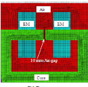
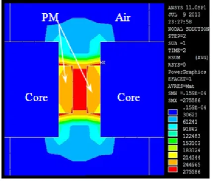
[image:2.595.340.526.84.266.2]Numerical analysis of an electromagnet, with and without permanent magnet, was carried out through a commercially available FEA tool (ANSYS, V-11) to study intensity and uniformity of the magnetic field. The 2D static magnetic field approach was used. Fig. 1 depict finite element model for electromagnet without permanent magnet. For meshing around 3000 elements of standard type 8-noded ‘Plane-53’ were selected with an axisymmetric behavior. These elements are derived from a magnetic vector potential formulation. The coupled degrees-of-freedom (AZ CURR) was used for conductors. DOF AZ (vector potential in z-direction) was used for air, iron and permanent magnets. While meshing global size control was used to control the element edge length. However, in the air gap zone, the size control was done by manually with ‘element division’ equal to 2. Perimeter boundary conditions were set to ‘flux parallel to nodes’ to obtain the magnetic field solution. Keeping constant current density for 2A as magnetic loading, differences in the results were plotted for both the cases of electromagnets. Figs. 2~3 show the flux trajectories for electromagnet and biased magnet, respectively. Results signify that the flux trajectories were more influencing between the poles of a biased magnet in comparison with that of pure electromagnet. Similarly, differences in the magnetic fields for both cases were simulated. Figs. 4~5 show the difference in magnetic field distribution for electromagnet and biased magnet actuation at constant current density. It was observed that the density of magnetic field has been increased by a magnitude of 110kA/m for biased magnet.
[image:2.595.318.546.279.479.2]Figure 1. Finite element model
Figure 2. Flux trajectories in electromagnet
[image:2.595.319.541.507.696.2]Figure 4. Magnetic field in electromagnet
Figure 5. Magnetic field in biased magnet
3.2. Experimental Setup
The experimental setup was designed and fabricated based on the numerical results. Magnetic field strength was observed inversely proportional to the air-gap between the poles. The magnetic flux density in the air gap with permanent magnets of 0.3T at the poles was simulated, to obtain the de-pinning flux value of 0.35T in the gap. The results were utilized for deciding the 10 mm thickness of the actuator. Fig. 6 depicts the setup. The setup consists of compact MSMA actuator assembly, electromagnet and permanent magnets. A compact MSMA actuator is as shown in Fig. 7. Non-magnetic materials of the actuator components have been used for fabrication to minimize any effect under the magnetic field. Actuator also has provision to adjust different pre-stress loading in the direction of the x-axis. The actuator material was five layers modulated, single tetragonal crystal NiMnGa alloy with dimensions 1mm thick, 18mm wide and 10mm long. The gap between two magnetic poles measured parallel to the z-axis was 10mm. The specimen was placed between the two magnetic
[image:3.595.317.552.134.281.2]poles in such way that the thickness oriented along the direction of z-axis. In this position of the specimen the magnetic energy required for material elongation and magnetization reduces.
Figure 6. Experimental setup with permanent magnets.
Figure 7. Schematic of compact MSMA
In the first case, the experimentation was carried out for only actuation of MSMA by an electromagnet in another case the MSMA was actuated through the combination of electromagnet and permanent magnets. The combinations of permanent magnets with 0.35T field between the poles were selected in the biased field from the point of de-pinning effect.
In all above cases, the specimen was pre-stressed about 1.5MPa to get de-pinning effect nearer to the selected permanent magnet field. The amplitude of the magnetic field in the actuator air-gap was controlled by regulating the excitation current. To measure the displacement response of the actuator, the laser pick-up sensor (Maker: Micro-Epsilon, Model: ILD 1402, Germany) with operating frequency up to 1.5kHz, was used. Magnetic flux density was recorded using the Gauss meter (Maker: Lakeshore, Model: 410, USA).
3.3. Experimental Results
[image:3.595.71.285.289.471.2] [image:3.595.316.552.308.463.2]In the electromagnetic actuation, it was observed that a sudden jump in displacement after 2A current, which corresponds to de-pinning effect. At the beginning point of de-pinning, the magnetic flux intensity of 0.35T was recorded using the Gauss meter and also displacement of 0.0019mm was recorded using laser pick-up. Corresponding to the de-pinning magnetic field, arrangements were made with the help of the permanent magnets to provide the necessary static field with strength 0.35T between two poles. Then the MSMA was subjected to biased field actuation. Fig. 9 depicts the variation of displacement with magnetic field in MSMA for both field actuations. The value of field and strain corresponds to de-pinning values. With the arrangement of permanent magnet in the electromagnet, the MSMA actuate directly from de-pinning point, under the net effect of biased field.
Figure 8. Variation of displacement vs. current
Figure 9. Variation of displacement vs. magnetic field. 3.3.1. Magneto-Strain Comparison
Elongation in MSMA, subjected to electromagnetic and biased actuation were plotted (Fig. 8) for regular interval of 0.4A and simultaneously magnetic fields were also recorded (Fig. 9). From the Fig. 8 at 4.25A current, the maximum displacement of 0.016 mm was observed in pure electromagnetic actuation whereas in the biased field actuation the displacement was 0.0137 mm. The reduction
was evident in biased field, due to the initial deformation of specimen under 0.35T permanent magnetic fields. It was observed that for biased field almost linear displacement in MSMA actuation was achieved. Moreover, the sudden rise due to the de-pinning effect in electromagnetic actuation was smoothened. In the case of biased field the displacement was higher for current up to 3.2A as compared to electromagnetic field. Since, the displacement of 0.056 mm, the current requirement was 2A in biased field actuation whereas in electromagnetic actuation 2.6A. Thus, a reduction in the current was achieved by 23%. Similarly, the reduction in final displacement of 14.37% was observed while switching to bias field actuation. As a whole, from the above study, an average of 75% increase in the displacement from the current up to 3.2A was achieved.
3.3.2 .Time Response for Actuation
The electromagnet coils were subjected to pulse current for generating a magnetic field to actuate MSMA specimen. Response time for MSMA actuation was measured by the laser pick-up sensor. MSMA actuation has its lagging due to hysteresis of an electromagnet, actuator moving mass and its inertia. Since, the measured responses were based on the comparison between the electromagnet and bias field of MSMA actuation with the same power input, response lag was same for both cases and hence the effect was neglected. In the experimentation, it focussed on the percentage difference in response time of actuation rather than actuating frequency of MSMA specimen.
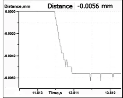
Time Responses at 0.0056mm displacement:
[image:4.595.77.283.454.629.2]From Fig. 8, for the displacement of 0.0056mm, current requirement was 2.6A and 2A in electromagnet and biased field actuation, respectively. Figs. 10~11 shows the time responses recorded for both actuations. In Fig. 10, time observed was 0.5s in electromagnetic actuation for 2.6A whereas, under biased actuation at 2A the time was 0.35s (Fig. 11). From the study, it was achieved that for the displacement 0.0056 mm, 30% faster response to a 23% reduction in current.
[image:4.595.334.531.567.725.2]Figure 11. MSMA response under biased magnet at 2A current for displacement 0.0056mm.
Figure 12. MSMA response in electromagnet subjected to 3.2A current
Figure 13. MSMA response in biased magnet subjected to 3.2A current.
Time Responses at 3.2A Current
From Fig. 8, at 3.2A current, both electromagnet and biased magnet actuate the specimen, for the narrow difference in the displacements. Fig. 12 shows the time response of 0.75s for displacement 0.0118mm under
electromagnetic actuation whereas Fig. 13 shows the time response of 0.6s for the displacement 0.0093mm under biased field actuation. Comparing the responses of a specimen for 3.2A current, 20% reduction in response time was achieved for biased field actuation.
Time Responses at 4A Current
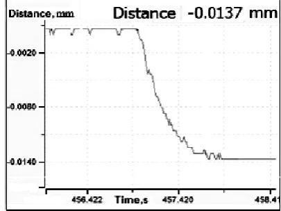
The MSMA sample was actuated at 4A current in both electromagnet and biased actuators. Response time and displacement for respective actuations were compared. Fig. 14 shows the time response of 1.1s in the 0.015mm displacement under electromagnetic actuation. Similarly, it was recorded 0.8s time response for the 0.0137mm displacement under biased field (Fig. 15). It was observed that 8.6% reduction in specimen displacement and 27.2% faster time response was achieved under biased field.
.
[image:5.595.322.533.272.431.2]Figure 14. MSMA response in electro-magnet subjected to 4A current.
Figure 15. MSMA response in biased magnet subjected to 4A current.
4. Conclusions
[image:5.595.75.282.292.453.2] [image:5.595.328.531.468.620.2] [image:5.595.75.279.492.654.2]demonstrate an improvement in the performance with an average 75% increment in initial magneto-strain and maximum 27.2% reduction in time response of the biased MSMA actuator at lower input power considered in the present study.
Acknowledgements
The authors are very grateful to Sir Robert O’Handley, Department of Material Science and Engineering, Massachusetts Institute of Technology, USA and Dr. Manickam Mahendran, Associate Professor of Physics (Materials Science), Thiagarajar College of Engineering, Madurai, India for providing single crystal NiMnGa sample for their research work.
REFERENCES
[1] Chernenko, V.A. and Besseghini, S. (2008) Ferromagnetic shape memory alloys: Scientific and applied aspects. Sensors and Actuators A 142, 542–548.
[2] Gauthier, J.Y., Hubert, A., Abadie, J., Chaillet, N. and Lexcellent, C. (2006) Magnetic shape memory alloy and actuator design. Proceedings of the 5th international workshop on micro-factories, IWMF'06, Besançon, France. [3] Glavatska, N. (2008) Origin of the time-dependent magneto
plasticity in the NiMnGa magnetic shape memory martensites. Materials Science and Engineering A, 481, 73–79.
[4] Gorbatenko, N., Grechikhin, V., Kolomiets, A., Kucherova, A. and Narakidze, N. (2011) Characterization of NiMnGa
magnetic parameters based on indirect measurements and modeling of experimental setup. The 6th international forum on strategic technology.
[5] Karaca, H.E., Karaman, I., Basaran, B., Chumlyakov, Y.I. and Maier, H.J. (2006) Magnetic field and stress induced martensite reorientation in NiMnGa ferromagnetic shape memory alloy single crystals. Acta Materialia 54, 233–245. [6] Kensuke, M., Noboru, N. and Katsuhiro, H. (2013) Study on
starting performance of NiMnGa MSMA linear actuator. IEEE Transaction on Magnetics, Vol. 49, No. 5, 2225. [7] Monner, M. (2005) Smart Materials for Active Noise and
Vibration Reduction. Keynote Paper – Noise and Vibration: Emerging Methods, Saint-Raphael.
[8] Riccardi, L., Naso, D., Janocha, H. and Turchiano, B. (2012) Precise positioning actuator based on feedback-controlled magnetic shape memory alloys. Mechatronics 22, 568–576. [9] Straka, L. and Heczko, O. (2004) Super-elastic response of
NiMnGa martensite in magnetic fields and a simple model. IEEE Transactions on Magnetics, Vol. 39, No. 5.
[10] Tickle, R., James, R. D., Shield, T. and Kokorin, V.V. (1999) Ferromagnetic shape memory in the NiMnGa system. IEEE Transactions on Magnetics, vol 35. No 5, 430.
[11] Ullakko, K., Huang, J. K., Kantner, C., O’Handley, R.C. and Kokorin, V.V. (1996) Large magnetic-field-induced strains in Ni2MnGa single crystals. Appl Phys Letter; 69:1966–8. [12] Xu, H., Wang, J., Jiang, C., and Li, Y. (2005) Ni–Mn–Ga
Shape Memory Alloys Development in China. Current Opinion in Solid State and Materials Science 9 - 319–325. [13] Wilson, S.A., Jourdain, R.P.J., Zhang, Q., Dorey, R.A.,