Journal of Chemical and Pharmaceutical Research, 2015, 7(3):1054-1061
Research Article
CODEN(USA) : JCPRC5ISSN : 0975-7384A two-stage damage identification method for space truss structure
Yang Chao-Shan, Cheng Hua, Wang Zhong-Gang, Wang Gao-Sheng
Logistical Engineering University, Chong Qing, P. R. China
_____________________________________________________________________________________________
ABSTRACT
To space truss structure, a two-stage damage identification method was proposed. First, using the modal force vector difference with small and low order modes to identify the damage bar of the space truss structure, then identifing the extent of damage through the analysis method of eigenvalue sensitivity by use of the modal frequency with easy-get and high accuracy characteristics. Numerical analysis show that this method can effectively identify different types, different quantity as well as varying degrees of injury bar. the algorithm of the method is simple, small computational workload , and is apply to actually truss structure damage identification.
Keywords: space truss; damage identification; modal shape; eigenvalue sensitivity
_____________________________________________________________________________________________
INTRODUCTION
Space truss structure as a common structural form has a very wide application in the construction, communication, electric power and other fields , under the influence of using the loading as well as the environment, it is extremely easy to cause the accumulation of damage and injury, which can be a serious threat to the structure's safe operation, thus, researches on the development of the structure of the space truss with the structural damage identification and safety evaluation, as well as timely maintenance and remedial measures, which have very high application value.
At present, using the method of structural damage data to identify the structure vibration data can be divided into dynamic fingerprint and inversion method. Dynamic fingerprint method is method which is mainly based on frequency, vibration mode, the modal strain energy and modal flexibility; while inversion method is mainly including analysis matrix optimization and sensitivity. As we know: the damage identification method based on frequency, vibration mode of the whole structure damage judgment is more effective [1-2], which is poor to the damage identification results of symmetric and complex structure; [3-4] while using strain damage identification method,it is sensitive to the bar and other fine damage, but it is very difficulty that a modal testing accuracy, order and freedom degree in the current measurement can be achieve,therefore, its actual application is limited. By using inversion method, matrix optimization, sensitivity analysis method can be better identified with slight injury, which also can realize the damage localization and quantification, but with the complexity of structure increases, the required test data and the recognition difficulty are increased rapidly, moreover, the algorithm is very complex with large amount of computation [5-6].
can verify the effectiveness of the method of damage identification of truss with two stages.
1 Modal force vector difference and damage location
With reference to the residual force vector in the form of [7]
∆
K
φ
id, defining the modal force vector difference, namely the index for damage localization:d i u
i
K
K
F
=
φ
−
φ
(1)In the formula superscript
u
represents the undamaged structure,d
represents the damaged structure, while.K
is the stiffness matrix of the whole structure.The structure before and after damage, its parameters can be approximately expressed as the form of the first order perturbation:
K
K
K
d=
u+
∆
, iu i d
i
φ
φ
φ
=
+
∆
,i u i d
i
λ
λ
λ
=
+
∆
(2)In the formula,
∆
K
,∆
φ
i can respectively represent the stiffness matrix of the whole structure, the perturbation matrix of structurei
,∆
λ
i can represent the perturbation value ofi
square value of frequency.i
φ
∆
can be expressed as a linear combination of the intact structure of various modes, according to the perturbation theory of the first order, the modal force vector difference can be expressed as:
∑
=
−
=
∆
−
=
nj u j ij i
i
K
K
c
F
1
φ
φ
(3)In the formula,
c
ij is the combination coefficient. It can prove [8]:
=
≠
−
∆
−
=
i
j
i
j
K
c
ui u
j u i T u j
ij
,
0
,
λ
λ
φ
φ
(4)
Modal force vector difference can be expressed as:
i
j
K
K
F
n
j
u j u i u
j u i T u j
i
≠
−
∆
=
∑
=
,
1
φ
λ
λ
φ
φ
(5)
By formula (5), with the right end of it, we can see, all items except for
∆
K
are intact structure parameters, therefore, the modal force vector difference only depends on the overall stiffness of the first-order perturbation matrix∆
K
, which can reflect the modal force vector difference positioning injury. In the early period of structural damage, the damage is often occurred in a few units, in the∆
K
matrix, its damage element namely the corresponding nodes are nonzero elements, thus, the modal force vector difference value can be the structural damage degrees of freedom most likely.By formula (1), which is known, modal force vector difference requires intact structure of the overall stiffness matrix before and after damage as well as the first-order complete mode shape vector difference, in practical application, when the measured degrees of freedom is less than structural degrees of freedom, it can use the extended model [9] or reduction model [10] .
2 The quantification of eigenvalue sensitivity and damage [9]
location of truss structure preliminary can use the eigenvalue sensitivity for more accurate quantitative study of damage.
By formula (2). We can know, the change of
j
eigenvalues can be determined by measuring the frequency before and after damage , i.e.:u j d
j
j
λ
λ
λ
=
−
∆
(6)As for the eigenvalue , by using Taylor series expansion and ignoring the two items. It can be obtained:
∑
=
∂
∂
∆
=
∆
Nei i j i j
a
a
1λ
λ
(7)In the formula,
N
e is the total number of structural units,∆
a
i is damage degree ofi j
a
∂
∂
λ
unit,
j
is known asthe first order sensitivity of the eigenvalues of E. Assuming structure does not cause quality change before and after damage, thus, the eigenvalue sensitivity is:
j i T j i j
K
a
φ
φ
λ
−
=
∂
∂
(8)
In the formula,
K
i is the whole stiffness matrix of coordinates unit.If
N
eigenvalue is acquired by measurement, then in the formula, (7) can be expressed as:
∆
∆
∆
×
=
∆
∆
∆
e N Na
a
a
S
M
M
2 1 2 1λ
λ
λ
(9)
In the formula,
S
is the characteristic value of the first-order sensitivity matrix, which can be obtained by finite element model: e e e e N N N N N N N Na
a
a
a
a
a
a
a
a
S
×
∂
∂
∂
∂
∂
∂
∂
∂
∂
∂
∂
∂
∂
∂
∂
∂
∂
∂
=
λ
λ
λ
λ
λ
λ
λ
λ
λ
L
M
O
M
M
L
L
2 1 2 2 2 1 2 1 2 1 1 1 (10)Thus, solving the damage degree vector can be expressed:
∆
∆
∆
×
=
∆
∆
∆
+ N NS
a
a
a
eλ
λ
λ
M
M
2 1 2 1(11)
In the formula,
S
+ is the inverse matrix of eigenvalue sensitivity of Moore-Penrose.L N L N N
N
L L
a
a
a
a
a
a
a
a
a
S
×
∂
∂
∂
∂
∂
∂
∂
∂
∂
∂
∂
∂
∂
∂
∂
∂
∂
∂
=
λ
λ
λ
λ
λ
λ
λ
λ
λ
L
M
O
M
M
L
L
2 1
2
2 2
1 2
1
2 1
1 1
(12)
By formula (12), we can know, after the damage element preliminary is determined, the characteristic value of the first-order sensitivity matrix will be significantly simplified, which is conducive to improve the accuracy of solution element damage degree, so as to reduce the number of feature frequency measurements which are of great help.
3 Numerical example
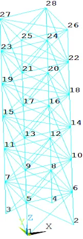
[image:4.595.275.356.339.572.2]This paper selects six segments (6 higher) of space truss structure as the object of study,in order to verify the effectiveness of the proposed method. The space truss cantilever structure bottom can be node consolidation, which can be consisted of 28 nodes, 108 bars, a total of 144 degrees of freedom, the structure is with finite element model which is as shown in Figure 1. Truss rod is circular cross section which diameter is
R
=
0
.
005
m
, it has the following characteristics: the material elastic modulusE
=
210
GPa
, Poisson's ratio is 0.3,while the density of the material isρ
=
7850
kg
/
m
3. [image:4.595.147.471.617.730.2]Fig 1 truss structure mode Table 1 the damage cases
Working Condition Rod type Injury Rod
The corresponding node
Freedom rod The degree of injury
Single damage
1 Chord 1418 54-59,78-83 -20%
2 The ventral rod 1420 54-59,90-95 -50%
3 Cross bar 1820 78-83,90-95 -50%
Multiple injury
4 Chord The ventral rod
0610 1824
6-11,30-35 78-83,114-119
-20% -50% 5 The ventral rod
The ventral rod 1016 1821
30-35,66-71 78-83,96-101
-30% -50%
6 The ventral rod 0609 1417 2126
6-11,24-29 54-59,72-77 96-101,126-131
-20% -50% -30%
bar can be considered, in order to consider the possible damage as many as possible, in the numerical example, by lowering the bar elastic modulus on the truss made loss, six damage cases can be set up, including single damage and multi-damage (shown in Table 1).
The structure is space truss structure, its vibration characteristics can be included multiple directions and torsional vibration, the example shows us that, the cross bar and the ventral rod can be mainly influenced by the direction of plane internal vibration type, which has not significant impact on the tangential direction vibration type , therefore, in the use of modal force vector difference of damage localization, in order to fully consider the planar bar and abdominal rod damage, this paper mainly uses the superposition of one or two modes, the damage condition of the truss rod position recognition cab shown in Fig. 2.
0 12 24 36 48 60 72 84 96 108 120 132 144 5
− 10
4
×
0 510
4
×
Fi
i a Damage working condition 1
0 12 24 36 48 60 72 84 96 108 120 132 144 5
− 10
4
×
0 510
4
×
F
i
i b Damage working condition 2
0 12 24 36 48 60 72 84 96 108 120 132 144 4
− 10
4
×
2
− 10
4
×
0 210
4
×
410
4
×
Fi
0 12 24 36 48 60 72 84 96 108 120 132 144 5
− 10
4
×
0 510
4
×
Fi
i d Damage working condition 4
0 12 24 36 48 60 72 84 96 108 120 132 144 4
− 10
5
×
2
− 10
5
×
0 210
5
×
410
5
×
Fi
i e Damage working condition 5
0 12 24 36 48 60 72 84 96 108 120 132 144 2
− 10
5
×
1
− 10
5
×
0 110
5
×
210
5
×
F
i
i F Damage working condition 6 Fig 2 the results of damage location identification
direction of Z and the reverse direction can be the modal frequency which is sensitive to the frequency, the extent of damage identification during the following process can mainly carry on the member damage assessment by using sensitive modal frequency. If you need to get the damage identification result more accurate, the iteration can use frequency change strategy to improve [12]. During the process of determining working condition 1 and 5 with the damage location discrimination, the value of undamaged degree of freedom modal force vector is larger, which has a certain interference, therefore, this paper only discusses the damage extent identification under working condition1 and working condition 5.
0 0 . 0 5 0 . 1 0 . 1 5 0 . 2 0 . 2 5
1 4 1 8 1 8 2 2 1 8 2 1 2 1 2 2 求解值 真实值
a Damage working condition5
0 0 . 1 0 . 2 0 . 3 0 . 4 0 . 5 0 . 6
1 6 1 8 1 0 1 6 1 4 1 6 1 8 2 1 1 0 1 4 求解值
真实值
b Damage working condition 6
Fig 3 the results of damage severity identification
Condition 1 (Fig. 2a), node 14, 18, 21, 22 as well as the corresponding degree of freedom with its modal force vector is quite different, therefore, the possible damage bar is 1418 chord, 1822 chord, 1821 rail brace and 2122 rail brace, by using the eigenvalue sensitivity method for solving the above 4 bars with the extent of the damage, we can get the degree of damage, which can be shown in Fig. 3a, among them, 1418 rod is 21.25%, 1822 bar is 3.68%, 1821 bar is 0.26%.
CONCLUSION
complete modal shape, when the measured degree of freedom can not meet the requirements, it can use the condensation model or modal expansion method.
Acknowledgement
The research was funded by the key scientific research project of Army Logistics (BS312J001), the basic and frontier research program in Chongqing City (cstc2013jcyjA30013); fund for Graduate Institute of Logistics Engineering.
REFERENCES
[1]Yiska.Goldfeld. Engineering structuers. 2009,31:1068-1076.
[2]Lam.Heung-Fai,Yin.Tao. Engineering structuers.2011,33:1459-1478.
[3]WU He-liang, XIE Ju-jing, XIONG-Zao. Journal of Vibration and Shock. 2012, 31(13): 105-107. [4]Dewangan.U.K. Engineering science and technology. 2011,10 (3):7587-7597.
[5]WANG Dan-sheng, GAO Zhi, YANG Hai-ping, et al. Journal of Vibration and Shock., 2009, 28 (11):122-125. [6]ZHANG Chun, SONG Gu-quan, WU Guang-yu. Journal of Vibration and Shock., 2010,29(9):1-4.
[7]GAO Wei-cheng, LIU Wei, QIAN Cheng. Engineering Mechanics.2007, 24(5): 93-100.
[8]FENG Xin, FAN Ying-fang, ZHOU Jing. Chinese Journal of Computational Mechanics. 2006, 23(5): 563-568. [9]ZHENG Fei, XU Jin-yu. Engineering Mechanics. 2012, 29(7): 117-123.