DEVELOPMENT OF CONTROL SYSTEM FOR A TWO WHEELED SELF-BALANCING TRANSPORTER
N MD HAFIZUL HASMIE B MOHAMED SUHAMI
A thesis submitted in
fulfillment of the requirement for the award of the Master of Electrical Engineering
Faculty of Electrical and Electronic Engineering Universiti Tun Hussein Onn Malaysia
ABSTRACT
ABSTRAK
CONTENTS
TITLE i
DECLARATION ii
DEDICATION iii
ACKNOWLEDGEMENT iv
ABSTRACT v
CONTENTS vii
LIST OF TABLE x
LIST OF FIGURES xi
LIST OF SYMBOLS AND ABBREVIATIONS xii
LIST OF APPENDICES xiv
CHAPTER 1 INTRODUCTION 1
1.1 Project Background 1
1.2 Problem Statement 2
1.3 Aim and Objective 2
1.4 Scope and Limitation 2
1.5 Organization of Thesis 3
CHAPTER 2 BRIEF REVIEW OF SELF-BALANCING TRANSPORTER 4
2.1 Introduction 4
2.2 Commercialize Product 5
2.2.2 Elektor Wheelie 6
2.3 Previous Work 7
2.4 Fundamental Principles 8
2.4.1 Inverted pendulum 8
2.4.2 Filtering (Complementary vs Kalman) 9
2.4.3 Control System 10
2.5 Summary 10
CHAPTER 3 METHODOLOGY 11
3.1 Introduction 11
3.2 Development Flowchart 12
3.3 System Design Block Diagram 13
3.4 Electronic System 14
3.4.1 Inertia Measurement Unit (IMU) 14
3.4.2 Controller Board 15
3.4.3 Motor Driver 16
3.4.4 Motors 17
3.4.5 Power Unit 17
3.4.6 Wireless Communication 18
3.5 Software Implementation 19
3.5.1 Accelerometer and Gyroscopes 19
3.5.2 Complementary Filter 21
3.5.3 PID Controller 21
3.5.4 Motor Controller Protocol 22
3.6 Frame Design 24
3.7 Summary 25
CHAPTER 4 RESULT AND ANALYSIS 26
4.1 Introduction 26
4.2 Accelerometer Measurement 26
4.3 Gyroscope Measurement 28
4.4 Complementary Filter 30
4.5 PID Controller 33
4.6 Balancing Control System 36
4.7 System Performance 41
4.7.1 Origin / Central Motion 41
4.7.2 Point-Point Route 44
4.7.3 Obstacle and Disturbance Handling 46
4.8 Summary 48
CHAPTER 5 CONCLUSION AND FUTURE WORK 49
5.1 Conclusion 49
5.2 Recommendation for future work 50
LIST OF TABLE
4.1 PID tuning response 35
4.2 Angle Speed Conversion (2 degree interval) 38
4.3 PWM and Motor Voltage Measurement 40
LIST OF FIGURES
2.1 General appearance of the Segway PT [1]. 5
2.2 General appearance of Elektor Wheelie [9]. 6
2.3 Inverted Pendulum Principle [15][16] 8
2.4 PID Control System Design [12] 10
3.1 Development Flowchart 12
3.2 System Design Block Diagram 13
3.3 5DOF IMU [Courtesy by Sparkfun] 14
3.4 Arduino Controller Board 15
3.5 Roboclaw Motor Driver [Courtesy by Orion Robotic] 16
3.6 24V DC brush motor 17
3.7 Wireless RF Module Interface [Courtesy by Seeed Studio] 18
3.8 The IMU rotating along X-axis 19
3.9 Basic block diagram of the complementary filter 21
3.10 PID Block Diagram 21
3.11 Motor Driver Serial Resolution Mapping 22
3.12 Matlab Graphic User Interface (GUI) 23
3.13 Frame Design 24
3.14 Framework Layer 1 25
3.15 Framework Layer 2 25
4.1 The IMU board measuring 0 degrees 26
4.2 Accelerometer effected by vibrations 27
4.3 Complementary Filter Output 31
4.4 Angle Error Measurement Setup 32
4.5 Complimentary Filter with PID Controller 33
4.6 PID Controller Tuning 34
4.7 Balancing Control System 36
4.9 PWM Signal Measurement 41
4.10 Origin / Central Motion Test 42
4.11 Origin / Central Motion Response 42
4.12 Point-Point Route Test 44
4.13 Point-Point Route Response 45
4.14 Bamboo Stick (2cm) Obstacle 46
4.15 Bunch of wired (0.5cm) Obstacle 46
4.16 Bamboo Stick (2cm) Response 47
LIST OF SYMBOLS AND ABBREVIATIONS
𝜃 - Accelerometer Angle 𝜃̇ - Gyro Angle
𝜕 - Speed serial variable 𝜃̂ - Angle variable 𝛼𝑖𝑛𝑚𝑖𝑛 - Angle min value 𝛼𝑖𝑛𝑚𝑎𝑥 - Angle max value 𝛽𝑜𝑢𝑡𝑚𝑖𝑛 - Gain min value 𝛽𝑜𝑢𝑡𝑚𝑎𝑥 - Gain max value
PID - Proportional, Integral, Derivative PWM - Pulse Width Modulation
LIST OF APPENDICES
APPENDIX TITLE PAGE
A Gantt chart 53
B CAD Drawing 54
C System Wiring Diagram 55
D Programming Flow Chart 56
E Source Code 57
CHAPTER 1
INTRODUCTION
1
1.1 Project Background
1.2 Problem Statement
The need of electric vehicle (EV) is to reduce the CO2 by zero emissions is the perfect solution. An electric vehicle like Segway / balancing transporter is suitable transportation but because of the power consumption its only can be used for short distance travel. The balancing transporter is a new way of travel device, its maneuverability is similar to a bicycle but still in highly cost of production. In other words the development of balancing transporter had two commitments that is to increasing efficiency of urban transportation for short distance travel and helping conserving the environment. There are many research done on this balancing transporter development. However the robustness of the system is not fully tested and more experiment needs to be performed to evaluate the robustness of the system and fine tuning of the control algorithm is required for better performance.
1.3 Aim and Objective
The aims was to design an electronic control system for two wheeled self-balancing transporter. The objective are as follows:
1.3.1 To investigate the characteristic of gyroscope and accelerometer sensor on Inertia Measurement Unit (IMU).
1.3.2 To develop a balancing control system of human transporter.
1.3.3 To analyse the system performance via real time plotting User Interface (UI).
1.4 Scope and Limitation
The design of balancing transporter has many approach that have been done by other researcher, for the project to be achievable in the given time, the scope of following constraints have been set.
evaluate by designing a MATLAB Graphic User Interface (GUI) verified on frame design as experimental platform. The work presented in this thesis does not involve the detail design of the hardware components, but focusing on the design of balancing controllers.
1.5 Organization of Thesis
This thesis is organized in five chapters that explain the theoretical aspect and development process of the project. These chapters are arranged in sequence order as follows:
Chapter II: Literature Review. This chapter discusses about studies and researches conducted by other scholars related to this project. The overview of history, comparison between various types of human transport devices, and its summary of features is presented in this chapter.
Chapter III: Methodology. This chapter describes the approaches used throughout the development of this project which covers theoretical analysis about the dynamics of the system, mechanism system of the device, and software implementation to control the whole operations of the device.
Chapter IV: Result and Analysis. This chapter presents the findings, observation and data collections of this project in form of tables, graphical methods and data points. These results are further analyzed and commented accordingly.
CHAPTER 2
BRIEF REVIEW OF SELF-BALANCING TRANSPORTER
2
2.1 Introduction
2.2 Commercialize Product
The balancing transporter works based on a new technology called "dynamic stabilization"[1]. It allows the transporter to work seamlessly with the body movements. Since the wheels of the transporter are parallel, it not keep itself upright at the midpoint. When the rider stands still, it resembles an inverted pendulum concept.
2.2.1 Segway
[image:16.595.264.364.400.576.2]The Segway Personal Transporter (PT) is a self-balancing electric vehicle which was invented by Dean Kamen in 2001 and produced by Segway Inc [1]. Figure 2.1 shows the general appearance of the vehicle. The Electronic Control Unit and electric motors are located at the base of the vehicle to keep the Segway in upright position.
Figure 2.1: General appearance of the Segway PT [1].
device starts to intentionally lean back. The Segway also reduces the speed or stops immediately if the handlebar of the device collides with any obstacle.
2.2.2 Elektor Wheelie
[image:17.595.274.365.342.521.2]The Elektor Wheelie [9] is a programmable Segway designed for control design experiments. The Elektor Wheelie kit is consist of two DC motors, two 12V lead acid batteries, two wheels of 16 inch diameter, the case of the platform, a casing control lever, and an assembled and tested control board with a sensor board installed. In appearance, the Elektor Wheelie is very similar to the Segway PT in Figure 2.2, but its mechanical and electrical structures are simpler, which makes it suitable for control experiments.
Figure 2.2: General appearance of Elektor Wheelie [9].
2.3 Previous Work
Abdalkarim M. Mohtasib and his group [11] has develop STEVE, is an applied research project to design, analyse, and construct an electric vehicle with two parallel wheels similar to Segway. The estimation of the tilt angle is done using Kalman filter. M. Abdullah Bin Azhar and his group [12] introduced SubukRaftar a simple self-balancing vehicles that only require a single physical input be sufficient for self-balancing as well as continuous movement by controlling behaviour of PID controller which has a digital filter and controller running on an AVR microcontroller. The Control variable, angle of platform is plotted using MATLAB to study response of the controller by complementary filter. H. Azizan and his team [13] introduced Fuzzy Control Based on LMI Approach and Fuzzy Interpretation of the Rider Input For Two Wheeled Balancing Human Transporter. They presents a Takagi-Sugeno fuzzy intelligent interpretation of the rider's body inclination. It provides an interface between human user and the vehicle with the aim to enhance the piloting capabilities and convenience from human user viewpoint.
2.4 Fundamental Principles
The balancing transporter is an unstable and nonlinear system. To make the balancing by itself some kind of control strategy has to be implemented. The following subchapter will handle the theory and fundamental Principles behind candidates for balancing controller.
2.4.1 Inverted pendulum
[image:19.595.184.458.424.571.2]The inverted pendulum in figure 2.3 is a classic problem in dynamics and control theory and is widely used as a benchmark for testing control algorithms such as PID controllers, state space, neural networks, fuzzy control, genetic algorithms, etc. Khalil Sultan [15] introduced by experimenting stabilization of the pendulum to shows the position of the carriage on the track is controlled quickly and accurately by the pendulum and its always maintained tightly in its inverted position during such movements.
Figure 2.3: Inverted Pendulum Principle [15][16]
2.4.2 Filtering (Complementary vs Kalman)
The challenge in balancing design is to determine of the real inclination angle of the platform. In comparison with the classical inverted pendulum, the angle is not directly measurable. It must be obtained indirectly after filtering the signal using one of these three options that is Accelerometer, Gyro, Combination of accelerometer and gyro. Shane Colton [17] from MIT said the inclination of the accelerometer is computed as a projection of the vector of gravity into the horizontal axis of the sensor but also the forward acceleration is projected into the measured signal and thus the angle can be computed very incorrectly. The gyro angle is obtained as the integration of the measured angular velocity. The problem is the drift of the gyro that can be eliminate by combination of accelerometer and gyro after be filtering using complementary filter.
Wasif, Ammar and his group [18] concluded that Complementary filter should be implemented due to its various advantages over Kalman Filter. The Kalman filter has a complex design compared to the design of the Complementary filter. Moreover, due to complex calculations involved in the Kalman filter it requires higher computational resources and time. Although Kalman filter has a more accurate result, but to save computational resources and time the Complimentary filter provides a good compromise.
2.4.3 Control System
[image:21.595.167.465.362.568.2]The development of the control system is essential to ensure success in balancing robot, while there are many control strategies that can be used to stabilize the robot, the main purpose is to control the system with cheap and efficient without sacrificing robustness and reliability of the controller. Differences in balance control algorithm implemented mainly depend on how the system is modelled and how the tilt information is obtained tilt. M. Abdullah Bin Azhar [12] finding method to stabilize the system by setup the control system running at 100Hz combine with complementary filter and PID control algorithm which controls the tilt angle is variable. Closed loop consists of Proportional (P), Integral (I) and derivative (D) components used in the method as shows in figure 2.4.
Figure 2.4: PID Control System Design [12]
2.5 Summary
CHAPTER 3
METHODOLOGY
3
3.1 Introduction
3.2 Development Flowchart
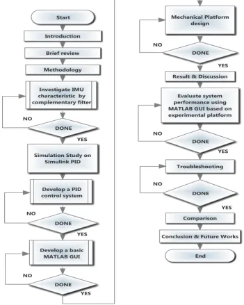
[image:23.595.138.490.292.732.2]Figure 3.1 shows the development flowchart of two wheeled self-balancing transporter as a guide line procedure on the development. The first approach need to be concern is the Inertia Measurement output angle that need to be filter using complementary filter because of unsustainable reading. The filtered angle next be transfer to PID control to reduce the error and the data will be recorded on MATLAB GUI. The electronic control system will be test on mechanical platform in real time to analyze the system performance so the corrective action can be made to optimum the system response.
3.3 System Design Block Diagram
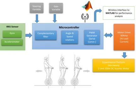
[image:24.595.111.545.440.727.2]A balancing transporter is a platform attached to a set of two independent wheels that is controlled by a DC motor. The platform attached to the wheel to make the system behave as inverted pendulum. Figure 3.2 shows the design layout block diagram to these features which is a common problem in engineering controls and processes to test a different control systems. Tilt angle measurement is implemented by inertial measurement unit (IMU) that consisting of gyroscope and accelerometer. Variable used to control steering motion steer either left or right. Gain variable is used to tune the signal response between the controller and the motor driver. Board controller process the input signal with a complementary filter and converting to speed PWM depending on an angle measurement. The angle manipulated by the controller to estimate the correct speed to compensate the platform and send it to the motor driver module by serial communication protocol. At the same time, the data from the controller processed and transmitted via wireless communication to Matlab GUI for performance analysis. The main goal of this process is to move the wheel in a certain position while keeping the center of mass of the system in an upright position.
Figure 3.2: System Design Block Diagram
Complementary filter Gyro IMU Sensor Accelerometer Angle & Speed relations PWM Generator (Serial Comm ) Motor Driver 60Amp (Hi Load Current) Microcontroller Experimental Platform (Hardware) 2 Unit 350w DC Scooter Motor Steering
Variable
Gain
Variable Wireless Interface to
3.4 Electronic System
3.4.1 Inertia Measurement Unit (IMU)
[image:25.595.168.488.494.658.2]The Sparkfun Inertia Measurement Unit Combo Board incorporates a dual-axis gyroscope IDG500 and Analogue Devices ADXL335 three-axis accelerometer in a tight footprint that enables unheard of 5 axis of sensing (Roll, Pitch, X, Y, Z). Figure 3.3 shows the physical board IMU in less than an inch board size for small PCB board installed. The board operated with 3.3V supply voltage that can be taken from the LM1117 voltage regulator at the controller. There are 3 output from the accelerometer that is X, Y, and Z axis are used to track the movements from three different directions (left-right, forward-backward and up-down). The roll and pitch of gyros has 4.5 gain value and detect the same direction as the accelerometer but without axis Z (up-down). For a sense of balance for balancing transporter platform, only two axes were included in the design for the YR axis of gyro and X-axis of accelerometer. These two types of analog output is connected to the analog input of the controller to process and get the angle represents the angle of the platform. There is a comparison between several type of IMU with different manufactured will be conducted for next experimental works to find the best response of balancing system.
3.4.2 Controller Board
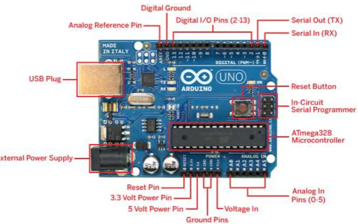
[image:26.595.134.495.406.632.2]Arduino in figure 3.4 is an open-source single-board microcontroller, the hardware consists of a simple open hardware design for the Arduino board with an Atmel AVR processor and on-board input/output support. For the UNO model, there is six analog input which is enough to support two analog signal from the IMU and two input variable for steering and gain respectively. The 3.3v power pin used to power up the IMU module and it has a plenty of digital I/O that can be used as output indicator. There also have a serial communication pin at pin 0 and pin 1. This pin is the same pin used for interface the Arduino board USB bootloader programming and to communicate between the controller and the motor driver module using simple serial communication protocol. Also, there is experimental works will be conducted using Arduino Mega which is provided with more analog input to process two unit of IMU simultaneously.
3.4.3 Motor Driver
[image:27.595.255.427.478.625.2]The RoboClaw 2x60 Amp motor controllers in figure 3.5 is a dual channel motor controllers. It can supply two DC motors push with 60 Amps continuous and 120 Amps peak. The RoboClaw also includes a 3 Amp switch mode BEC that can power up any device from RoboClaw. To be able to control the speed and direction of the motor specific motor driver are be used. Motor driver is a small circuit board with a microprocessor itself that have a serial communication protocol. It can independently and simultaneously control two motors in different speeds and directions by receiving a control data in serial bit format. The board is fed with 24 Volt from the power supply to the motor and the internal circuit was regulated by 5 Volt operations that suitable with internal microcontroller embedded at the motor driver. Each motor can be controlled with a resolution of 8 bits. By submitting a value between 1 and 127 of the first motor is controlled 1 full reverse, 64 is stop and 127 correspond to full speed ahead. The second motor is controlled in the same way, but the numbering bit is in between of 128 and 255, where 128 is full reverse , 192 is stop and 255 is full speed ahead . One of the serial port on the controller board that is used for this communication physically.
3.4.4 Motors
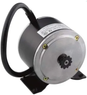
[image:28.595.267.414.249.408.2]The motors driving the platform are mounted on the structure and the wheels are placed by gear chain socket ratio of 27:11 on the outgoing shaft of the motor. This is a powerful 24V DC brush motor that is used in electric scooter that comes with no gear reduction, maximum power 350 W and 2600 RPM maximum speed. The motor comes with an 11 teeth sprocket. An image of scooter motor is shown in figure 3.6.
Figure 3.6: 24V DC brush motor
3.4.5 Power Unit
3.4.6 Wireless Communication
[image:29.595.169.483.441.617.2]The balancing transporter is equipped with a wireless module for wireless communication between computers. The module which is used is type known as “serial cable replacement”. There are two suggestion type of communication which is either RF Module or Bluetooth module. The RF module operates at Radio Frequency and the corresponding frequency range varies between 30 kHz & 300 GHz. In this RF system it’s operated with 315 MHz frequency signal up to 100 meters depending on the antenna design, working environment and supply voltage impact the effective distance. Meanwhile the Bluetooth module has built-in Bluetooth stack which makes the connection and use with the computer board easy by automatic serial pipeline data transfer. When the device is opened, sending and receiving is done in the same way as write and read to a file or a COM port. By using Arduino UNO as a controller the communication pin must be create as an imaginary or virtual comport either one from the digital pin because the physical serial communication TX RX pin used by motor driver module to communicate as shows in figure 3.7.
3.5 Software Implementation
The software controlling the balancing transporter is developed in regular C, and for more specific it run on open source platform which is an Arduino C compiler that run on Arduino UNO controller board. One feature added in this case is the real-time performance analysis by Matlab GUI interfacing via imaginary serial port. To give the software a good structure, it is divided into a number of separate files or subroutine.
3.5.1 Accelerometer and Gyroscopes
The normal range for Arduino 1bit Analog to Digital Converters (pin AA5) is 0-1023, where 0V input produces a value of 0, and 5V input value, 1023. By using 3.3V Arduino analog input, the maximum value of the Arduino can read from the sensor is approximately 675 by (3.3V / 5V * 1023). To get the full range of 3.3V device, the desired reference voltage 3.3V should connected to the analog reference (Aref) of Arduino pin and add a coding to initialize the Arduino, to use an analog reference. This method will change only the analog reference voltage input pins (A0-A5) and not change any other input or output pin which is still produces a 5V signal.
[image:30.595.147.475.557.685.2]The accelerometer measures the gravitational force of the IMU relative to the horizon. To equal 0 degrees the IMU must be parallel to the horizon. If the IMU board is tilted left or right in figure 3.8, the angle measurement yields a proportional value in either direction. The code is set to shut down the motors in the event that the IMU measures an angle above the limit.
Figure 3.8: The IMU rotating along X-axis 90
Seemingly the function of accelerometer can used to detect the angle of the IMU board. The reason it’s not suitable to use only to detect angular acceleration is that it severely affected by gravity. Any sudden change in gravity or vibration can affect the angle of the accelerometer output, although the point has not changed. This can drastically change the output readings, the signal becomes useless by distortion signal and need to apply some filtering to prevent false readings. Unfortunately, vibrations and bumps are unavoidable when riding a balancing transporter, this is where a gyroscope sensor comes in handy to solve the problem.
Gyroscope measures how many degrees per second. The measurement of gyroscope value angle is difficult to be measured because it can measure only the rate of change. Gyroscope sensor indicates the current changes while moving along the axis and when stop moving, the voltage drops back to the state capital. Gyroscope drift which refers to the tendency to deviate from the starting point, although it’s not move. These errors make it difficult to get the right angle without accelerometer to use as a reference point for point.
3.5.2 Complementary Filter
[image:32.595.177.461.241.366.2]Complementary filter in figure 3.9 is used to obtain an estimate of the signal from the two sources of information that is from accelerometer and gyroscopes. The Complementary filter get estimates by filtering the signal through complementary architecture, which means that if one of the signal is interrupted by high-frequency sound, then it choose a low-pass filter.
Figure 3.9: Basic block diagram of the complementary filter
3.5.3 PID Controller
The PID (Proportional Integral Derivative) controller will used in the design to reduce an error in angle measurement from the Inertia Measurement Unit (IMU). The measured tilt angle from the complementary filter will send to the input (set point) of PID algorithm in figure 3.10, meanwhile the angular velocity from the gyroscopes will send to the PID as a feedback response of close loop system.
[image:32.595.199.453.595.709.2]3.5.4 Motor Controller Protocol
[image:33.595.176.464.310.503.2]Motor controller is programmed to accept a simple serial protocol that allows the series forward and back to control the speed of the two motors as shows in figure 3.11. The Roboclaw accepted the value of data in between of 0 until 255 in the range of the Byte. Bytes are used to control Motor1 (1-127) and (128-255) bytes used to control Motor2. Both the range of values each split into front and back to the center position. There are 64 steps speed control in either direction for each the motor, providing enough resolution and smooth acceleration.
3.5.5 Matlab GUI Development
[image:34.595.120.558.274.628.2]GUIs in figure 3.12 shows a provide point and click control of software applications build using Matlab software to evaluate the performance of balancing transporter. The GUIs plot the real time graph of accelerometer angle, gyro angle and filtered angle. The RAW analog data of IMU signal, Steering Signal and Gain Signal also be display as a reference for wiring evaluation and analysis. The motor data transferred value can be monitored especially the response of motor value be added with the gain signal.
Figure 3.12: Matlab Graphic User Interface (GUI) Real Time
Graph
IMU Analog
Steering Value
Gain Value
Acc & Gyro RAW
Angle
Temp Value
Filtered
Angle Link
3.6 Frame Design
[image:35.595.85.519.260.570.2]Frames provide a rough shape of the balancing transporter. Figure 3.13 shows the frame structure for balancing transporter using Solidworks sketch and the actual hardware after development. The weight of the frame is important, because it affected the dynamics of the balancing transporter. Materials selected for handlebar is aluminum profile, lightweight and easy to mount on other components, besides that the mainframe based hollow metal structure to support a heavy weight load.
Figure 3.13: Frame Design
The frame in figure 3.14 is made by hollow metal by sized of 36 inch x 24 inch, cut into two pieces upper and lower frame. The thickness of the frame is around 6 inch, serves as the electronic part compartment. The handlebar design can be extend and retract by 48 inch length to suite the rider height. To keep the weight centre between the wheels, the batteries are housed in front of the compartment base using shows in figure 3.15. The battery cage must be larger enough to house the two SLA batteries which measure 6 inch L x 4 inch W x 3.8 inch H each. The entire frame assembly connects to each motor gear box using eight 8mm bolts.
Gyro & Accelerometer Unit
Power 24v 7A
Safety Button
REFERENCES
1. U. Segway Inc., Bedford, NH, “Segway Inc.,” Segway Inc., 2007. [Online]. Available: http://www.segway.com.
2. U. Nagarajan, “Fast and Graceful Balancing Mobile Robots,” no. July, 2012. 3. D. Banister, Unsustainable Transport: City Transport in the New Century.
Routledge Taylor & Francis, 2005.
4. C. B. Jan Burck, Franziska Marten, The Climate Change Performance Index. Germanwatch, 2013.
5. M. R. Bageant, “Balancing a Two-Wheeled Segway Robot by,” 2011. 6. H. Juang and K. Lum, “Design and Control of a Two-Wheel Self-Balancing
Robot using the Arduino Microcontroller Board,” 2013.
7. R. C. Ooi, “Balancing a Two-Wheeled Autonomous Robot,” 2003. 8. A. GÖÇMEN, “Design of Two Wheeled Electric Vehicle,” ATILIM
UNIVERSITY, 2011.
9. Elektor, “Elektor Wheelie Elektor’s DIY self-balancing vehicle,” Elektor Magazine, pp. 44–45, Jun-2009.
10. C. Krohn, “Elektor Wheelie The electronics behind a rather special kind of vehicle,” Elektor Magazine, pp. 66–71, 2009.
12. M. A. Bin Azhar, W. Hassan, and U. Rahim, “PID Control Behavior and Sensor Filtering for a Self Balancing Personal Vehicle,” 2012, pp. 7–10. 13. H. Azizan, M. Jafarinasab, S. Behbahani, and M. Danesh, “the Rider Input For
Two Wheeled Balancing Human Transporter,” 2010, pp. 192–197.
14. M. Han, K. Kim, D. Kim, and J. Lee, “Implementation of U nicycle Segway U sing U nscented Kalman Filter in LQR control,” pp. 695–698, 2013.
15. A. M. Khalil Sultan, “Inverted Pendulum,” Institute of Industrial Electronics Engineering, 2003.
16. J. R. & A. S. H.-M. Maus, S.W. Lipfert, M. Gross, “Upright human gait did not provide a major mechanical challenge for our ancestors,” Nat. Commun., 2010.
17. S. Solution, I. Accelerometer, G. Measurements, B. Platform, S. Colton, and C. Delphi, “The Balance Filter,” 2007.
18. A. Wasif, D. Raza, W. Rasheed, Z. Farooq, and S. Q. Ali, “Design and implementation of a two wheel self balancing robot with a two level adaptive control,” Eighth Int. Conf. Digit. Inf. Manag. (ICDIM 2013), pp. 187–193, Sep. 2013.
![Figure 2.1: General appearance of the Segway PT [1].](https://thumb-us.123doks.com/thumbv2/123dok_us/8764361.895625/16.595.264.364.400.576/figure-general-appearance-segway-pt.webp)
![Figure 2.2: General appearance of Elektor Wheelie [9].](https://thumb-us.123doks.com/thumbv2/123dok_us/8764361.895625/17.595.274.365.342.521/figure-general-appearance-elektor-wheelie.webp)
![Figure 2.3: Inverted Pendulum Principle [15][16]](https://thumb-us.123doks.com/thumbv2/123dok_us/8764361.895625/19.595.184.458.424.571/figure-inverted-pendulum-principle.webp)
![Figure 2.4: PID Control System Design [12]](https://thumb-us.123doks.com/thumbv2/123dok_us/8764361.895625/21.595.167.465.362.568/figure-pid-control-system-design.webp)
![Figure 3.3: 5DOF IMU [Courtesy by Sparkfun]](https://thumb-us.123doks.com/thumbv2/123dok_us/8764361.895625/25.595.168.488.494.658/figure-dof-imu-courtesy-by-sparkfun.webp)
![Figure 3.5: Roboclaw Motor Driver [Courtesy by Orion Robotic]](https://thumb-us.123doks.com/thumbv2/123dok_us/8764361.895625/27.595.255.427.478.625/figure-roboclaw-motor-driver-courtesy-orion-robotic.webp)