Radial Basis Function Network based MPPT for Photovoltaic System during
Shading Condition
ABD KADIR Mahamad
a*and SHARIFAH Saon
bFaculty of Electrical and Electronic Engineering
Universiti Tun Hussein Onn Malaysia
86400 Parit Raja, Batu Pahat, Johor, MALAYSIA a[email protected], b[email protected]
Keywords:Solar photovoltaic; MPPT; RBF; Perturb & Observe
Abstract. The output powers of photovoltaic (PV) system are crucially depending of the two variable factors, which are the cell temperatures and solar irradiances. A method to utilize effectively the PV is known as a maximum power point tracking (MPPT) method. This method is extract the maximum available power from PV module by making them operates at the most efficient output. This paper presents Radial Basis Function (RBF) Network to control the MPPT of PV system. The performances of the controller is analyzed in four conditions with are constant irradiation and temperature, constant irradiation and variable temperature, constant temperature and variable irradiation, and variable temperature and irradiation. The proposed system is simulated by using MATLAB-SIMULINK. According to the results, RBF controller has shown better performance during partially shaded conditions.
Introduction
PV power generation systems have intensively been investigated as an environment-friendly technology since 1970s because of their advantages of infinite energy resources and no carbon dioxide (CO2) emission
[1]. Furthermore, it is crucial to operate PV energy conversion systems near maximum power point (MPP) in order to increase the output efficiency of PV [2]. Nevertheless to obtain the MPP required a method to let the controller operate at the mentioned optimum operating point. Hence, many tracking control technique have been developed and implemented. The most common techniques that have been used are such as Hill-Climbing/Perturb and Observe, constant voltage, neural network and fuzzy logic [3-8]. At the same time, these techniques have some drawback such as fail to track MPP during partially shaded, low irradiance conditions, costly and due to system complexity.
The primary purpose of this project is to design the optimum controller based on RBF network to track the MPP of photovoltaic system. This is due to the PV can’t effectively produce the MPPT in certain time especially during shading condition and has been identified as a main cause for reducing energy yield of many PV. There have many reason lead to the PV array had be shaded, for instance; from buildings, trees, chimneys and the dust or dirt on the module’s surface. Furthermore, another threat lead to non-uniform irradiance is cloudy day. This factor is unavoidable issue. During the cloudy day, the non-uniform irradiance lead to more complicated current-voltage (I – V) and power-voltage (P – V) with multiples local MPP. Consequently, it is essentially to develop a suitable MPPT controller to solve this issue.
To sum up, this project is to analyze and compares the simulation result of RBF network in four conditions with are constant irradiation and temperature, constant irradiation and variable temperature, constant temperature and variable irradiation, and variable temperature and irradiation.
Methodology
There are several things should be considered in development of this project. Methodology is a process that has to be followed when analyzes data and designing a project. The process includes the method, technique, and the tools/equipments/software that have been used in this project.
PV Model. Simulation tools provide the opposite view to the design tools. The user specifies the nature and dimensions of each component and the application provides a detailed analysis of the characteristics of the system. The accuracy of calculations and the simulation time required varies depending on the level of detail required and the type of data provided. They are used to verify the sizing of the system and investigate the impact of future changes in the systems being simulated.
In the first place is to describe the solar panel which constitutes the main source of power for the whole photovoltaic installation. The equivalent model of the electrical circuit is used as the main element of the panel which formed by a current source that depends on the solar radiation in W/m2, temperature in Celsius degrees (T), a shunt diode whose intensity of inverse saturation in series depends on the temperature and a resistance (RS), which represents the effect of the internal resistance of each solar cell and the contacts of the generator as it is.
The equation is solved by designing a program in MATLAB, taking into account the number of solar cells which has the photovoltaic panel. The main equation is shown as in Eq. (1):
1
1
1 a Tak T
Iph
Iph T (1)
where, Tak is working temperature and IphT1 is photocurrent at the working temperature. The T1 can be
calculated by substitute the Eq. (2) into Eq. (1)
Suns Isc
IphT1 T1 (2)
a is the ratio of short circuit current at T1 and the short circuit current at T2, can be calculated using Eq. (3)
2 1
1 1 2 T T Isc Isc Isc a T T T
(3)
with IscT1 is current of short circuit at temperature T1and IscT2 is current of short circuit at temperature T2.
The saturation current is show in eEq. (4), whereby b is equal to Vgq/
Ak
; Vg is diode voltage which is equal to 1.12 eV for crystalline Silicon <1.75 for amorphous silicon.
T TC
b A rT r e T Tak I I 1 1 3 1 Ref 1 Ref (4)
where TRef is reference temperature.
The photocurrent Iph is directly proportional to solar radiation IRA which taking into account a constant of proportionality, according to the Eq. (2). The terms of reference are: solar radiation (IRA = 1 sun = 1000 W/m2), atmospheric mass (AM=1.5) and temperature (T = 25 °C).
Eq. (3) [10]. Finally the value of diode ideality factor A is referring to the data appears in the specifications sheets and is provided by the manufacturer. In this project the Solarex MSX -60 photovoltaic module is used for research. The Typical Electrical Characteristics of MSX -60 PV modules are in Table 1.
Table 1: Solarex MSX -60 Specifications
By knowing all the important required equations of the generalized PV model, the generalized PV model subsystem can be built up. The entire system has been modeled on MATLAB™ 2010b and SIMULINK™. The block diagram of the solar MSX -60 PV modules is shown in Fig. 1.
Figure 1: Masked block diagram of the modeled solar MSX -60 PV
MPPT Algorithm using RBF. All the MPPT algorithms are designed to dynamically extract the maximum power from the PV panels. Usually, the condition ∂p/∂v = 0 is adopted to locate this operating point, since PV panels show a unique global MPP. The MPPT algorithms are based on the determination of the slope of the PV panel’s output power versus voltage, i.e., the power derivative ∂p/∂v. This quantity is utilized as representative of the “voltage error”, i.e., the difference between the actual voltage of the PV panels and the reference voltage v* corresponding to the MPPT. In the region nearby v* the power derivative can be considered a straight line having the slope k. In order to determine the power derivative ∂p/∂v it is necessary to introduce a voltage and current perturbation around any operating point of the PV array. Traditional MPPT algorithms are based on “perturbation and observation” method or “incremental conductance” method [11]. In this research, perturb and observe (P&O) method have been chosen to assist the RBF in order to find MPP during partial shading.
On the other hand, RBF has several advantages, one of which is that it usually trains much faster than other network. RBFN is less susceptible to problems with non-stationary inputs because of the behavior of the RBF on hidden units. The input layer consists of source nodes (input data), whose number is equal to
Electric parameter MSX -60
Maximum power, Pmax 60 W
Maximum current (short circuit output), Imp 3.5 A
Maximum voltage (open circuit), Vmp 17.1 V
Short circuit current, Isc 3.8 A
Open circuit voltage,Vsc 21.1 V
Temp. coefficient: short-circuit current (0.065±0.015)%/°C
the dimension n of the input vector u. The second layer is the hidden layer, which composes nonlinear functions that are connected directly to all of the nodes from the input layer.
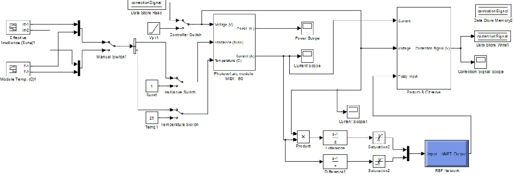
[image:4.612.49.568.186.364.2]For RBF, the connection between input and a hidden layer is determined by using distance weight before it proceeds to the ‘radbas’ of a nonlinear function. The training process for RBF network is simple. Once the error goal is set, the training will start until the error goal is met, then the numbers of hidden nodes are confirmed. After this process, the output layer is obtained by simply applying the ‘purelin’ function between a hidden layer and an output layer. In this study, mean square error goal (goal), spread of radial basis functions (spread), maximum number of neurons (mn), and the number of neurons to add between displays (df) are 1E-12, 0.01, 200, and 20 respectively. The proposed RBF controller is shown as in Fig. 2.
Figure 2: The proposed RBF controller for PV module
Results and Analysis
The performances of perturb & observe (P&O) and RBF controllers are analyzed in four conditions: 1) Constant irradiation and temperature
2) Constant irradiation and variable temperature 3) Constant temperature and variable irradiation 4) Variable temperature and variable irradiation
The metrics that are used to measure the performance are the maximum power, voltage and current achieved by the solar panel and the time for the controller to reach MPP.
Comparison of Temperature and Irradiation Effects on P&O versus RBF Controller Algorithm.
Table 2: Comparison of Temperature and Irradiation Effects on P&O and RBF Algorithm
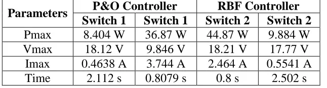
Comparison of P&O and RBF Controller (Variable temperature and variable irradiation). The results from Table 3 have shown the P&O and RBF controller in two different stages. Which, the inputs for these two controllers are analyzed by the two categories variance irradiance and temperature which called switch 1 and switch 2. Switch 1 is represented normal irradiance which is sunny day. On the other hand, switch 2 is represented partially shaded conditions. For case 1, both of the controllers are turned to switch 1. The result for the maximum power of the RBF controller is higher than the P&O controller. The RBF controller is able to reach the MPP within 0.8 seconds for a maximum power of 36.87 W. In contrast, when the switch is turned to switch 2, the maximum power of RBF controller is still higher than the P&O controller. These results show the RBF network gave good performance during normal and partial shading condition.
Table 3: Comparison of Two Different Temperature and Irradiation Effects on P&O and RBF Controller
Conclusion
This paper has presented model of PV module and the development of the MPPT techniques. The performances of the controllers are analyzed in four conditions which are constant irradiation and temperature, constant irradiation and variable temperature, constant temperature and variable irradiation and variable temperature and variable irradiation. The proposed system is simulated by using MATLAB-SIMULINK. Based on the simulation result, the project is successfully achieving the objective.
From the simulation result, RBF controller has shown the better performance than P&O controller during normal and partial shading. The maximum power for RBF controller are 36.87 W and 44.87 W during normal and partial shading condition respectively compared with P&O which only gave 8.404 W and 9.884 W. According to the results shows the proof that RBF controller is the optimum controller compared with P&O controller. For the future work this research can be apply on FPGA board, which the RBF controller algorithm can be load to the board for real application.
Parameters
P&O RBF controller
Constant Irr, Const Temp
Constant Irr, Variable
Temp
Variable Irr, Const Temp
Constant Irr, Const Temp
Constant Irr, Variable
Temp
Variable Irr, Const Temp
Pmax 64.44W 69.92 W 7.695 W 64.44 W 69.68 W 57.43 W
Vmax 18.1V 19.7 V 17.6 V 18.11V 19.64 V 16.33 V
Imax 3.56A 3.549 A 0.43 A 3.559A 3.548 A 3.516 A
Time 0.8 s 1.199 s 0.8 s 0.823 s 0.8928 s 0.8 s
Parameters P&O Controller RBF Controller Switch 1 Switch 1 Switch 2 Switch 2
Pmax 8.404 W 36.87 W 44.87 W 9.884 W
Vmax 18.12 V 9.846 V 18.21 V 17.77 V
Imax 0.4638 A 3.744 A 2.464 A 0.5541 A
[image:5.612.126.449.420.507.2]References
[1] Toshihiko Noguchi, and Hiroyuki Matsumoto: Maximum Power Point Tracking Method Of
Photovoltaic Using Only Single Current Sensor, Journal of Electrical Engineering in Japan, Vol. 160, Issue 1 (2007), p. 79–86
[2] S. Premrudeepreechacharn, and N. Patanapirom: Solar –Array Modeling and Maximum Power Point Tracking Using Neural Network, Power Tech Conference Proceedings, IEEE Bologna, Vol. 5 (2003)
[3] R. Messenger and G. Ventre, Photovoltaic Systems Engineering, Second Edition Wiley (2003)
[4] C. C. Lee, Fuzzy-logic in control-systems: Fuzzy logic controller, Part I. IEEE Trans Syst Man Cybern, Vol. 20(2) (1990), p. 404-418
[5] Syafaruddin and HIYAMA,Takashi: ANN Based Optimal Operating Points of PV Array under Partially Shaded Condition, International Conference on Electric Engineering (2008)
[6] B. Amrouche, M. Belhamel and A. Guessoum, Artificial Intelligence Based P&O, MPPT Method for Photovoltaic Systems, Revue des Engergies Renouvelables ICRESD-07 Telmcen (2007), p. 11 -16
[7] A.J Mahdi, W.H Tang and Q.H Wu: Improvement of A MPPT Algorithm for PV Systems and Its Experimental Validation, International Conference on Renewable Energies and Power Quality (ICREPQ’10) Granada (Spain) (2010)
[8] Adel El Shahat: Maximum Power Point Genetic Identification Function for Photovoltaic System, IJRRAS3 (3) (2010)
[9] Y.Lei, Z.He and Y.Zi: Application of an intelligent classification method to mechanical fault diagnosis, Expert Systems with Application, Vol. 36, no.6 (2009), p. 9941-9948
[10] L. Castaner, Modelling Photovoltaic Systems Using PSpice. CRC Press (2002)