Model studies of plasma heating in the continuous casting
tundish.
BARRETO SANDOVAL, Jose de Jesus.
Available from Sheffield Hallam University Research Archive (SHURA) at:
http://shura.shu.ac.uk/19322/
This document is the author deposited version. You are advised to consult the
publisher's version if you wish to cite from it.
Published version
BARRETO SANDOVAL, Jose de Jesus. (1993). Model studies of plasma heating in
the continuous casting tundish. Doctoral, Sheffield Hallam University (United
Kingdom)..
Copyright and re-use policy
Sheffield Hallam University
ProQuest Number: 10694203
All rights reserved INFORMATION TO ALL USERS
The quality of this reproduction is dependent upon the quality of the copy submitted. In the unlikely event that the author did not send a com plete manuscript and there are missing pages, these will be noted. Also, if material had to be removed,
a note will indicate the deletion.
uest
ProQuest 10694203
Published by ProQuest LLC(2017). Copyright of the Dissertation is held by the Author.
All rights reserved.
This work is protected against unauthorized copying under Title 17, United States C ode Microform Edition © ProQuest LLC.
ProQuest LLC.
789 East Eisenhower Parkway P.O. Box 1346
Model Studies of Plasma Heating in the
Continuous Casting Tundish
Jose de Jesus Barreto Sandoval
A thesis submitted in partial fulfilment of the
requirements of
Sheffield Hallam University
for the degree of Doctor of Philosophy
April 1993
To:
Adriana and Daniel
ACKNOWLEDGEMENTS
I would like to acknowledge the influence of Professor A W D Hills for his contagious
enthusiasm for the subject, originality, superb teaching skills, continuous guidance and
encouragement. Dr. D M Allen-Booth for his receptivity, encouragement, and his
valuable ideas. Who as supervisors, both have a great share of my acknowledgements
concerning to this work.
Particular thanks to Mr. N. Dziemidko for his continuous assistance and help during
the experimental work, and for his friendship during the completion of this thesis.
I also would like to thank Mr. B. Palmer and Mr. R. Wilkinson for their ready
availability and assistance during the experimental work.
To my fellow students, at the School of Engineering for their help and friendship at
various stages of the work. Particular thanks to C. Brashaw for his friendship, long
discussions and his help during the writing-up stage.
Technicians, administrative staff, secretaries, librarians, and other members of the staff
at Sheffield Hallam University for their prompt and efficient services.
CONACYT - Mexico, for the financial support.
I am grateful to my wife Adriana for her constant encouragement, patience, toleration
ABSTRACT
A room temperature water model of a tundish was design, constructed and operated.
The model was equipped with a steam heating system that simulates that simulates the
tundish plasma heating systems operated by some of the more modem continuous
casting plants. Similarity between steam heating in the water model and plasma heating
in the tundish has been established. A dimensionless criterion was developed to validate
the simulation experiments and its represented by the plasma heating number. Using this
similarity criterion plasma heating can be simulated by steam heating in an
appropriately designed water model.
A theoretical dispersion model has been formulated for the flow through the tundish and
the parameters in this model determined from the results obtained from residence time
distribution measurements. A conductivity method was used, a highly conducting
species being injected at the inlet point and changes in conductivity monitored at the
exit. Measurements were also made of the changes in temperature at the exit resulting
both from changes in temperature of the inlet stream and from the use of steam heater
system.
A stable inverse heat conduction method has been developed in which the measured and
estimated temperature are analysed in terms of a steady components of short duration.
A finite difference method has been used to predict the effect on a thermocouple
temperature of the deviatory components of the liquid steel temperature. The
incorporation of these predictions into look-up tables has allowed an algorithm to be
CONTENTS
Page
ACKNOWLEDGEMENTS iii
ABSTRACT iv
LIST OF SYMBOLS ix
1 INTRODUCTION
1.1 Foreword 1
1.2 The objective of the investigation 2
2 LITERATURE SURVEY 3
2.1 General overview 3
(a) Development of continuous casting 4
(b) Quality requirements for the continuous
casting products 5
2.2 Fluid flow aspects of tundish operations 5
(a) Mathematical modelling 6
(b) Physical modelling 10
(c) Radioactive tracer studies 18
2.3 Heat transfer in tundish operations 24
(a) Mathematical modelling 24
(b) Physical modelling 26
2.4 The role of auxiliary heating 28
2.5 Continuous temperature measurement of liquid steel
Contents
Page
3 EXPERIMENTAL TECHNIQUES 39
3.1 Development of water model systems 39
(a) Model design calculations 39
(b) The tundish model 44
(c) The ladle 45
(d) Water heating system 45
(e) Steam heating system 46
3.2 Experimental techniques to determine residence time
distributions 47
(a) Choice of tracers 48
(b) Preparation and addition of the tracers 48
(c) Conductivity measurements 49
(d) Temperature measurements 49
3.3 Experimental techniques for remote temperature sensing 50
(a) Method of temperature measurement 50
4 THEORETICAL DEVELOPMENT 52
4.1 Theoretical dispersion model 52
(a) The dispersion model 54
(i) Pulse input in tracer concentration 55
(ii) Step input in tracer concentration 60
Contents
Page
4.2 New approach to the inverse heat conduction problem 66
(a) The general equation of heat conduction 67
(b) The finite difference analysis 74
(c) Boundary conditions
(i) Finite outer surface heat transfer theory 78
(ii) Finite inner surface heat transfer theory 83
(d) The use of numerical techniques to estimate internal
surface temperature 88
(i) Theory of internal wall temperature estimation 88
5 EXPERIMENTAL RESULTS 92
5.1 Treatment of data 92
5.2 Determination of the dispersion parameter 95
(a) Determination of the dispersion parameter for the
tundish model using different flow control devices 97
(b) Determination of the dispersion parameter for the
tundish model using the steam heating system 100
5.3 Estimation of internal surface temperature 104
(a) Theoretical simulation experiments 105
Contents
Page
6 DISCUSSION 154
6.1 Accuracy and errors of the experimental method 154
(a) Flow rate measurement 156
(b) Conductivity measurement 157
(c) Temperature measurement 158
6.2 Modelling of plasma heating 158
(a) Plasma heating similarity criteria 158
(b) Thermal striation similarity criteria 162
6.3 Characteristics of the flow control configurations 165
6.4 Prediction of temperature decay 166
6.5 Temperature compensation by using the steam heating system 168
6.6 Estimation of internal surface temperature at the entry and
outer nozzles 172
(a) Theoretical simulation experiments 172
(b) Experimental measurements 174
(i) Heat transfer coefficient estimation 175
6.7 Application of the IHCA in the continuous casting tundish 179
7 CONCLUSIONS 180
8 FURTHER WORK 183
9 REFERENCES 184
LIST O
F SYMBOLS
Symbol Meaning SI Units
A area m2
C concentration kmol m'3
Cp heat capacity J kg'1 °K'1
Ce dimensionless concentration [ - ]
Cmean mean concentration kmol m'3
Dj longitudinal dispersion coefficient m2 s'1
d distance m
d nozzle diameter m
df depth of fluid in the tundish m
dp depth of penetration of the heat wave m
F flow rate of molten steel kg Sec'1
F0 dimensionless fractional temperature [ - ]
g acceleration due to gravity m s'2
h fluid depth m
h heat transfer coefficient W m'2 °K'1
K total kinematic energy J
k thermal conductivity W m'1 °K'1
L characteristic length m
Ld plasma heater "dog-house" length m
1 Prandtl mixing length m
lf length scale factor
Symbol Meaning SI Units
flow rate scale factor [ - ]
q”
heat flux W nr2r distance from the centre line m
T temperature °C
t time s
tf time scale factor [ - ]
t mean residence time s
u velocity m s'1
V stream velocity m s'1
vf
velocity factor m s'1V volume m3
^dead dead volume of the tundish m3
^mixed mixed volume of the tundish m3
^plug plug flow volume of the tundish m3
Greek Characters
a thermal diffusivity m2 s'1
(3 constant
f t temperature coefficient of volume expansion °K‘1
e rate of dissipation of turbulence kinematic J Kg
V
1
energy/unit mass of fluid or m2 s'3
M molecular viscosity m2 s'1
Mt turbulent viscosity Pa s
Symbol Meaning SI Units
v kinematic viscosity Pa s
0 s "steady state" surface temperature °C
0 M measured temperature °C
0 ‘ current partial temperature °C
©M deviatory temperature measured °C
©surf current estimate of surface temperature °C
6 temperature °C
Ad average rise in fluid temperature resulting from
heat input °C
0 dimensionless sampling time [ - ]
p mass density Kg m'1
a variance [ - ]
a surface tension N m'1
At temperature pulse duration - time interval s
r dimensionless time [ - ]
t p characteristic dwell time by the fluid beneath the
1
I
NTRODUCTION
1.1 FOREWORD
The temperature of liquid steel during the continuous casting is one of the basic
indicators of operation and quality control. In the past decade, the requirements for high
quality steel have increased dramatically, with more emphasis on superheat control and
an ever need for better automation. Auxiliary heating and continuous temperature
measurement in the tundish have become indispensable technologies for the modem
continuous casting process.
It has been long recognized that superheat plays a key role in determining the structure
and properties of continuously cast products, therefore to achieve quality and ease of
operation the casting temperature must be controlled as closely as possible.
Low temperatures of tundish superheat promotes fine equiaxed grains in the largest part
of the section, consequently the segregated areas are small in size and distributed in the
volume, thus preferred microstructures can be achieved with low tundish superheat. On
the other hand, as the tundish superheat is increased, the index of micro-inclusions is
reduced, this effect might be assumed to be due to the decrease in viscosity at higher
temperatures. An optimum tundish superheat is one that tends to minimize chemical
segregation and the occurrence of inclusions in the product yet avoids freezing-off
Chapter 1 - Introduction
1.2 T
H
E OBJECTIVE OF THE INVESTIGATION
The basic objective of the present work is to investigate whether the temperature at
which liquid steel enters the mould of a continuous casting machine can be controlled
dynamically from indirect measurements of liquid steel temperature at a point of entry
to the tundish.
This consist of:
(i) Studying the fluid flow of liquid steel through a tundish using water
modelling techniques.
(ii) Modelling plasma heating using a steam jet in the water analogue model.
(iii) Measuring residence times distribution from tundish inlet to outlet.
(iv) Measuring residence times distribution from heater to tundish outlet.
(v) Matching applied heat to input "steel" temperature to maintain constant
output temperature.
(vi) Developing a device sensor system to monitor input and output
2
LIT
ERATURE SURVEY
2.1. GENERAL OVERVIEW
' In the past couple of decades, it has been recognized that tundish superheat and the melt
flow in tundishes has a marked influence on the quality of steel. Thus many steel
companies and research laboratories have employed mathematical and physical
modelling to simulate melt flow in tundishes. An importan recente development in
tundish design has been the consideration of plasma heating and continuous temperature
measurement to control tundish superheat.
In order to understand the effectiveness of providing thermal energy supplied at the top
of the steel flowing in the tundish and to study its response and controllability, it is
important to appreciate the key developments of previous works.
The objective of the present literature survey is not to be an exhaustive review of the
literature, but rather to enable the experimental results and conclusions to be considered
in their right perspective, and to serve as a basis on which the new ideas and theories
Chapter 2 - Literature survey
(a) Development of continuous casting.
Continuous casting has become an increasingly important step in the manufacture of
steel in the past two decades. The continuous casting process is increasingly replacing
the conventional ingot casting route for the manufacture of finished steel products
worldwide, because of the inherent advantages. They are, principally:
i).- Energy savings and the potential for reducing energy consumption
through hot charging of continuously cast products to the rolling mill
furnace.
ii).- Increased productivity, 10% and more higher yield compared to
conventional ingot casting.
iii). - Higher quality and more uniform final product.
iv).- Reduced operating, capital and depreciation costs.
v).- Improved safety and working conditions for the operators.
vi).- Good environmental conditions.
vii).- Process suited for integral automation.
Because of the increased productivity and the operating costs benefits, it is expected that
the continuous casting process will dominate the production scheduled of most
steelmaking plants in the near future, especially in the view of the technological
Chapter 2 - Literature survey
(b) Quality requirements for the continuously cast products.
Concurrent with the development of the continuous casting technology, the quality
requirements of the final steel product have become very stringent. These quality
aspects - mainly surface finish and internal cleanness - have become determining with
the gradually increasing machine throughputs and larger products dimensions.
Therefore, steel cleanness, tundish superheat and strict composition control are now the
primary concern of steelmakers. After investigation, it has been recognized that the
interaction between the three processing parameters: temperature, composition, and
fluid flow, determine the processing response in terms of both quality and productivity.
Several authors have found that the melt flow in tundishes has a marked influence on
the quality of cast steel products.
2.2.
FLUID FLOW ASPECTS OF TUNDISH OPERATIONS
Fluid flow behaviour plays an important role in the whole process of continuous casting
with regard to the quality of the final product, the ease of operation and productivity.
Fluid flow in steelmaking tundish vessels has been the subject of extensive study, the
approaches used have included mathematical modelling, physical modelling and
Chapter 2 - Literature survey
(a) Mathematical modelling
Mathematical modelling has been stimulated in recent years by the ready availability of
computer facilities and software packages to predict flow patterns in tundish systems.
However, the fundamental equations which describe fluid flow are often too complex
to be solved even using large computers, since the computations require the
simultaneous solution of a number of highly non-linear equations. For instance, the
continuity and the three components of the Navier-Stokes equations fully describe fluid
flow behaviour, but they are extremely complex and their solution requires
simplifications and assumptions to be made about a number of aspects, for example the
choice of a turbulence model to represent the effective viscosity and the treatment of
the boundary conditions and numerical methods of solution. The fundamental equations
and the simplifications and assumptions chosen, make up a mathematical model. It is
obvious that such mathematical models need to be validated against experimental
measurements.
Several such models have been developed to represent fluid flow in continuous casting
tundishes, involving the solution of two and three-dimensional Navier-Stokes and the
continuity equations.
The model developed by Debroy and Sychterz[1] is a two-dimensional one, the flow
Chapter 2 - Literature survey
the Navier-Stokes equations in two-dimensions. For the computation of the turbulent
viscosity, /a, the hypothesis of mixing length given by Prandtl is used, which is written
as:
'aA
(2.i)
Where: p: density of the medium
(jl,: turbulent viscosity
1: Prandtl mixing length
(du/dy) : Absolute value of the velocity gradient along a direction
perpendicular to the direction of flow
The mixing length is defined
as:-l - OAd (2-2)
Where: d : is distance to the nearest wall
The effective viscosity is expressed
Chapter 2 - Literature survey
Where: pett: Effective viscosity
p: Molecular viscosity of the medium
A three dimensional mathematical model was introduced by Tanaka et. al.pl to predict
fluid flow patterns in tundish systems. The fundamental equations used were the
continuity and the three-dimensional turbulent Navier-Stokes equations, incorporating
the K-e turbulence model of Jones and Launder[3,4] to calculate the turbulent viscosity.
There, turbulence is expressed by two transport equations for the turbulence kinematic
energy K and its rate of dissipation e. The relation between ^ and the two turbulence
characteristics
is:-H, - KjpA^/e
(2.4)
The governing equations for K and e are,
respectively:-8X;
\pUiK
_
MM)
a K dx, G - pe(2.5)
_a_
dx. e dx,i j
( K . G - K . p e ) ^
K(2.6)
Where:
G -T1du,
dxt
( du, du.x
Chapter 2 - Literature survey
K: Turbulent kinetic energy
e: Rate of dissipation of turbulent kinetic energy
G: Generation of turbulent energy
A*eff: Effective viscosity
ixt: Turbulent viscosity
k15K2, K3, crK, ae: Empirical constants
The above equations were solved together with boundary conditions. The results were
found to be in good agreement with the experimental results obtained from a one-sixth
scale water model.
Similar mathematical models have been developed by Lai et. al.[5] and by Szekely,
Ilegbusi and El-Kaddah[6,7] to study fluid flow in tundishes when flow control devices,
such as dams and weirs, were employed. Another one was developed by He and
Sahai[8,9] to study the effect of tundish wall inclination on the fluid flow and mixing, the
results found were in good agreement with those measured experimentally in a one-third
scale water model. More recently, Sahai and co-workers[10j have shown the influence
of the finite difference grid spacing on the predicted fluid flow and the residence time
distribution by comparison of computed results from the K-e model of turbulence and
Chapter 2 - Literature survey
The solution procedures of the mathematical models of fluid flow in steelmaking
tundishes are mainly through the solution of finite difference equations which are
derivided from the governing differential equations. Thus the methods involve the
derivation of finite difference formulations from the differential equations and boundary
conditions as well as methods for solving the resulting set of simultaneous non-linear
equations. Nowadays, some of the methods for the solution of the fundamental
equations of turbulent two and three-dimensional flow, such as those encountered in
tundish operations, have been embodied in computational fluid dynamics packages, such
as PHOENICS, TEACH(2D,3D), FLUENT, FLOW3D, FLOW-3D, FLOWDIA, etc.
(b) Physical modelling
The flow of liquid steel in a steelmaking tundish systems is very difficult to observe
directly, with the exception of open pouring streams. The application of mathematical
modelling is often too complicated by the occurrence of turbulence in some regions of
the system. Thus, physical modelling, using water models, is an attractive alterative for
the study of fluid flow in the tundish and mould. The key requirement for the physical
model to represent the real system, or the prototype is to achieve the criteria for
similarity.
There exist many states of similarity; however, to obtain similarity between two flowing
Chapter 2 - Literature survey
i) Geometric similarity
Geometric similarity is the similarity of shape. Systems are geometrically similar when the ratio of any length in one system to the corresponding length in the
other system is everywhere the same. This ratio is usually termed the scale
factor.
ii) Kinematic similarity
Kinematic similarity represents the similarity of motion. The streamlines in one
system are geometrically similar to the streamlines of the other system.
iii) Dynamic similarity
Dynamic similarity represents the similarity of forces. The magnitude of forces
at corresponding location in each system is in a fixed ratio.
iv) Thermal similarity
The dimentionless numbers involving heat transfer are equal in both systems.
Kinematic similarity between prototype and model is ensured if geometric and dynamic
similarities are observed. The principal forces to be considered in obtaining dynamic
Chapter 2 - Literature survey
The principal dimentionless groups which involve these forces are given by:
Froude No Fr - - _ J ? ertia l force
gL gravitational force
Reynolds No Re - Y k - E n f o r c e
v viscous force
Weber No We - inertial force___
a surface tension force
Where: V: Stream velocity
g: Gravity
L: Characteristic length
v\ Kinematic viscosity
a: Surface tension
p: Density
Absolute dynamic similarity requires that each of the dimensionless groups listed above
have the same value in both the model and the prototype. Due to the difference of the
physical properties of water at room temperature and molten steel, table 2.1, it is
impossible to satisfy simultaneously all of the requirements for similarity which applies
Chapter 2 - Literature survey
requires a full scale model. The Weber-Froude similarity requires a model of 0.6 scale.
Some numerical values for the applicable dimensionless groups are presented in table
2
.2
.TABLE 2.1 Physical properties of water at 20°C and steel at 1600°C.
Property Water
(20 °C) (1600°C)Steel
Absolute Viscosity (cp) 1 6.40
Density (g/cm3) 1 7.08
Kinematic Viscosity (cs) 1 0.90
Surface Tension (dyne/cm) 7.3 1600
TABLE 2.2 Calculated values for various dimensionless grups in the steel and water model systems.
Number Steel System Full Scale Water Model
Reynolds 1 1.1
Froude 1 1.0
Weber 1 3.1
Morton 1 44.0
Modified Froude 1 7.0
It has been demonstrated by Heaslip et. al.[11] that the Froude number can be satisfied
Chapter 2 - Literature survey
requires a full scale model. The Weber-Froude similarity requires a model of 0.6 scale.
Some numerical values for the applicable dimensionless groups are presented in table
2
.2
.TABLE 2.1 Physical properties of water at 20°C and steel at 1600°C.
Property Water
(20 °C) (1600° C)Steel
Absolute Viscosity (cp) 1 6.40
Density (g/cm3) 1 7.08
Kinematic Viscosity (cs) 1 0.90
Surface Tension (dyne/cm) 7.3 1600
TABLE 2.2 Calculated values for various dimensionless grups in the steel and water model systems.
Number Steel System Full Scale Water Model
Reynolds 1 1.1
Froude 1 1.0
Weber 1 3.1
Morton 1 44.0
Modified Froude 1 7.0
It has been demonstrated by Heaslip et. al.[11] that the Froude number can be satisfied
at any scale in a tundish water model as long as all metering orifices and fluid hydraulic
Chapter 2 - Literature survey
what scale of model should be used, the extent to which similitude is necessary in
modelling the actual system must be considered.
(i) Experimental methods.
The experimental methods used to study fluid flow in the continuous casting tundish via
water modelling are the stimulus-response method and the elapsed-time photographic
technique.
The residence time distribution, this is the departure of actual residence times from the
mean, of the fluid flowing through a tundish can be determined by the use of the
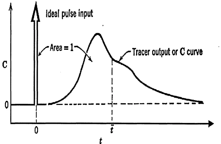
stimulus-response method. Basically, this involves the addition of a tracer, such as a
dye or a chemical substance, to the stream entering the tundish and then measurement
of the concentration at the exit. Several techniques have been developed for introducing
the tracer material into the system, but the most important are the step input and the
pulse input. These have been described by Levenspiel[41].
When taking pictures of the fluid flow pattern in water models, the following techniques
are available for fluid flow visualization:
i) Particle-addition into the water system
ii) Dye injection into the stream
iii) Use of a slit light source to illuminate the fluid flow domain
Chapter 2 - Literature survey
For the quantitative description of the fluid flow pattern, the following methods can be
used to measure the flow velocity at certain points of the domain:
i). Impact tube and static pressure tap with manometer.
ii). Form drag strain gauge system with strain amplifier and recorder.
iii). Laser doppler anemometry
iv). Thermistor probe.
v). Hot film anemometry
vi). Stroboscopic photography.
The literature describing water modelling using the above experimental methods to
describe fluid flow in tundishes is extensive.
A full scale water model of a slab caster tundish has been used by Kemeny et al.[121 so
that Reynolds and Froude similarity criteria could be satisfy simultaneously. It was
found that flow into a tundish from a poured ladle stream was not beneficial to product
quality owing to air and slag entrapment within steel. Stagnant regions were present
which prevented a significant portion of the tundish volume being usefully used. This
naturally lowered mean residence times within the tundish from those nominally
expected, hindering effective separation of buoyant non-metallic particles from the
molten steel before draining into the mould.
Weirs were found to be effective in confining the turbulence generated by the ladle
Chapter 2 - Literature survey
tundish was smooth, allowing the presence of a coherent protective layer of slag. It was
also shown that with proper weir placement, stagnant areas could be eliminated and
mean residence time within the tundish could increased. Dams were shown to be more
effective than weirs in damping surges in metal flow. As these methods successfully
increased the retention time greatly, the authors argued that the separation of
non-metallic particles would be greatly enhanced.
A one-third scale water model of a typical slab tundish was used by Sahai and Ahujatl3]
to investigate the effects of various flow control devices, such dams, weirs, slotted
dams and submerged gas injection, on the flow characteristics. In this study, the Froude
number similarity was maintained between the model and the prototype.
It was shown that in open stream pouring, the plunging jet entrains significant volume
of air or gas, in an inert gas shrouded stream. The entrained air causes a strong upward
buoyancy force and the liquid flow in this region is reversed. The liquid stream loses
its downward momentum on entering the tundish and reverses to the free surface, where
it flows downstream towards the tundish-mould nozzle.
It was found that in a tundish without any flow control devices a stagnant volume of
about 23%. Whilst the use of a weir helped to push the liquid down, thus reducing the
dead region found in the previous case. Nevertheless, this weir created a dead region
behind it, and the stagnant volume was calculated as 17%. The addition of a dam
Chapter 2 - Literature survey
the use of one or two slotted dams. Each of this physical control devices created a slow
secondary recirculation in the downstream region behind the device. The use of gas
injection in conjunction with the physical control devices decreased the dead volume by
activating the slow recirculating liquid and considerably increased the dispersed
plug/dead volume ratio. Gas injection, however, did not have much effect on the mixed
volume fraction. The gas stream acted as a barrier to longitudinal mixing but
contributed to fluid mixing in the vertical direction. The completely mixed volume
fraction varied from approximately 0.45 to 0.52 for various configuration studied.
This study also shows that during submerged stream pouring, liquid enters the pool with
sufficient downward momentum to carry it right to the bottom. The configurations with
no flow control devices have a slightly smaller dead zone of about 17%. Addition of
a weir or a dam at the given positions increased the dead volume for reasons similar
to those of open stream pouring. Again, it was found that the gas injection did not
increase substantially the mixed volumes in the tundish.
Similar approaches towards improving flows in the tundish of a slab caster at the
Kashima works of Sumitomo, were suggested, based on water model experiments by
Hashio et. al.[14], a variation of shapes and depths of liquid tundishes were proposed.
Dobson et. al.[15] also carried out similar experiments in reduced and full scale water
models of two different tundishes in use by BHP, Australia. They solved the
three-dimensional Navier-Stokes equation in a transient mode to describe the fluid flow,
Chapter 2 - Literature survey
improved flow control device placements and geometries in actual plant tundishes.
Significant improvements are reported.
(c)
R
adioactive tracer studies
In contrast to the large number of reported investigations concerned with mathematical
and physical modelling studies, the open literature available on the radioactive tracer
studies in operating tundishes is rather scanty. Measurements on a plant scale are
highly desirable, but not straightforward.
Martinez et. al.[16] presented a comparison between water modelling test results and
tracer measurements in real systems. The pulse input technique was used to determine
residence time diagrams, for water models and for the experiments with Cu64 in the real
tundish. The residence time distribution curves obtained from a one-third scale water
model and from a 12-tonnes tundish of a five-strand billet caster machine are presented
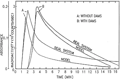
in figure 2.1, where it is shown to give good agreement in one case and moderately
good agreement in the other between the water model and the real system.
Van der Heiden and co-workers[17] carried out similar experiments to study the flow
behaviour of liquid steel in a boat-shaped tundish with a capacity of 60 ton, in order to
improve the separation of inclusion particles. Copper tracer was added using step input
techniques, for this the copper content in an intermediate ladle in a sequence casting
Chapter 2 - Literature survey
0.2
-A: WITHOUT DAMS B: WITH DAMS
TIME (MIN)
Figure 2.1. Residence time diagrams for real system and model (Vb scale). (From Martinez et. al. 1986)
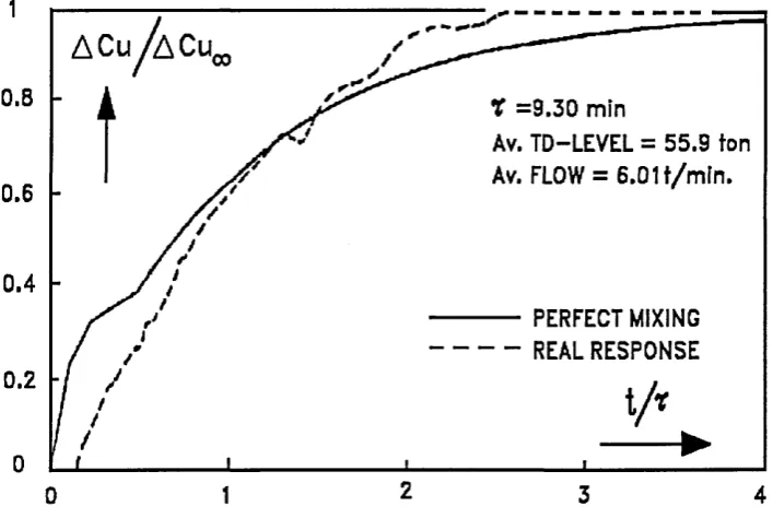
in the period near the ladle change. The copper concentration was determined by
sampling the mould at 15 seconds intervals, the residence time distributions are
presented in figures 2.2 and 2.3, for the absence of flow control arrangements and in
the presence of flow control arrangements, respectively. In this real system it was also
found that applying dam and weirs the minimum residence is increased, and it was
[image:34.612.91.505.76.346.2]Chapter 2 - Literature survey
X
= 9.26 MIN.Av.TD-LEVEL = 60.7ton Av.Flow = 6.54 t/m ln .
PERFECT MIXING REAL RESPONSE
0.2
[image:35.613.129.483.389.626.2]2
Figure 2.2. Step response of the tundish without obstacles; Cu (tracer): 0.012% to 0.070%. (From Van der Heiden et.al. 1986)
0.8 T =9.30 min
Av. TD-LEVEL = 55.9 ton Av. FLOW = 6.01 t/m ln.
0.6
0.4
PERFECT MIXING - - REAL RESPONSE
0.2
2 3 4
0
Chapter 2 - Literature survey
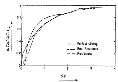
The results of this investigation have been compared to theoretical predictions by
Ilegbusi and Szekely[18]. The K-e model was employed and the results were generated
using the PHOENICS code. Figures 2.4 and 2.5 show the comparison between the
experimentally measured and the theoretically predicted "F" curves, that is the response of the system to a step change of tracer concentration. It is seen that reasonably good
agreement is obtained in both cases.
0.8
0.6
Perfect Mixing
Real Response
Predictions
0.2
t
f r [image:36.612.103.482.258.522.2]►
Figure 2.4. Measured and predicted response of steel system to a step change in a tracer concentration in the absence of the flow control. (From Ilegbusi et.al. 1988)
More recently Lowry and Sahaitl9] investigated the effect of multiple-hole baffles on the
steel flow in a six-strand tundish using tracer measurements, mathematical and water
modelling. The research concentrated on measurements and calculation of the residence
Chapter 2 - Literature survey
t
3 o
<3
3 o
<3
o.e
ii
0.6
0.4
Perfect Mixing
Reaf R esponse
fVedictions
0.2
[image:37.613.96.488.95.370.2]t/T
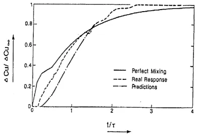
Figure 2.5. Measured and predicted response of steel system to a step change in tracer concentration in the presence of flow control. (From Ilegbusi et.al. 1988)
the real system and by calculation using the K-e turbulence model equations. A
symmetrical half of the "T"-shaped tundish was considered for the computations.
The results presented from the actual tundish trials show that adding baffles to the
system alters the flow in the tundish, increasing the mean residence time for the steel
to the inside nozzle, accompanied by a slight decrease in residence time to the outside
nozzle. This effects on the flow produced a more uniform distribution of liquid steel to
Chapter 2 - Literature survey
Good similarity was found between the results obtained by tracer studies and
mathematical and water modelling. However, comparing the mean residence time for
the nozzles, the mathematical model results were somewhat different quantitatively,
especially for the outside nozzles. The results of the water model and that of the actual
tundish are in better agreement with the mathematical model, which predicted higher
residence times in both inner and outer nozzles.
Lowry and Sahai argue that the discrepancies among the water model, mathematical
model and the actual tundish are that the tracers used had higher density than the fluid,
and tended to flow closer to the bottom, reaching the nozzle faster. For the
mathematical model the density is constant changing the concentration only. Also, the
temperature of molten steel is higher close to the ladle stream and therefore its density
is lower. This density difference in the liquid produces a buoyancy force which acts to
modify the fluid flow in the tundish.
For the inner nozzles a smaller discrepancy among tracer experiments and the
theoretical model was shown, which was explained by the combination of effects in the
real tundish not characteristic of the model, the incoming steel is hotter and less dense
than the melt in the tundish, causing it to flow up towards the free surface, and the
dense copper tracer would have the tendency to bring the copper-containing melt down.
These two effects seem to neutralize each other and the residence time distribution
Chapter 2 - Literature survey
The main discrepancy was found in the residence time distribution in the outer nozzles.
The combination of effects described above were not seen, mainly because the
temperature gradient in the molten steel is considerably reduced by the time the melt
reaches the end of the tundish.
2.3. H
EAT TRANSFER IN TUNDISH OPERATIONS.
The temperature of liquid steel plays one of the most important roles in determining the
structure and properties of continuously cast products. It is well established fact that
heat losses occur in the ladle during transfer operations, so that the temperature of
metal stream entering and leaving the tundish will vary with time, a precise knowledge
of heat losses in the tundish itself is highly desirable. Mathematical modelling has been
used to quantify the heat transfer process and its effects on the melt flow; and recently
water models have been used to visualize thermal effects on the flow pattern during the
tundish operations.
(a) Mathematical Modelling
Recently, computational modelling has become a useful tool to study heat transfer in
steelmaking tundish vessels. In order to describe heat transfer in industrial tundishes,
the relevant partial differential equations requiring numerical solution are:
Chapter 2 - Literature survey
-Momentum balance equation
-Energy conservation equation
-Turbulent kinematic equation
-Dissipation rate of turbulent energy equation
Using the above fundamental equations together with the boundary conditions and simplifications Ilegbusi and Szekely[20,21] developed a mathematical representation to
describe the temperature profile in tundishes, as affected by both flow control and
auxiliary heating arrangements.
The governing equations with the boundary conditions were solved with a finite domain,
fully implicit iterative procedure embodied in the Phoenics computer code. Computation
required about five hours of CPU time on a microVAX II.
The principal findings were as follows:
-When no auxiliary heating was provided, more significant heat losses occurred
in the absence of flow control devices.
-Auxiliary heating was found to be a potentially attractive way of compensating
the heat lose in the tundish and for providing a rather more precise temperature
control of these systems.
-Plasma heating is an effective way of providing thermal energy where there is
strong mixing and high turbulence, in order to obtain higher dispersion of the
Chapter 2 - Literature survey
reduces mixing and thus interferes with the ready absorbtion of the thermal
energy provided by the thermal jet. In contrast, Induction heating and the
associated stirring would be an effective way of rising the tundish temperature
in the presence of flow control devices.
Similar mathematical models were developed by Joo and Guthrie122,231 assuming steady
state flows and heat losses, and by Chakraborty and Sahai124,25,261 for both steady and
unsteady state conditions, to predict the effect of varying ladle stream temperature
conditions on the melt flow and heat transfer in steelmaking tundish vessels.
(b) Physical Modelling
Water modelling has improved understanding of the way in which liquid steel flows in
tundishes and interacts with different flow control devices. Most of the research
published on physical simulation of fluid flow in tundishes has assumed isothermal
conditions. Very recently, hot-water models have been used to visualize the effects on
the flow profile that take place during the ladle change operation when hotter steel is
poured into the tundish containing a relatively cooler melt.
To study the changes in melt flow characteristics during ladle changes, and whether hot
and cold water can be used to simulate thermal changes taking place in actual tundish,
Lowry and Sahai[27] measured the residence time distribution for an actual six-strand
Chapter 2 - Literature survey
It was found that the measured residence time distributions using copper tracers in an
actual tundish indicated that the flow following a ladle change is radically different from
the flow under isothermal, steady state conditions in the late half of the ladle cast.
Following a ladle change, the new steel entering the tundish at a higher temperature
than the present steel actually reaches the nozzle at the end of the tundish before it
reaches the nozzle closest to the pouring stream, except for a brief interval immediately
after the ladle change.
It was also concluded that a water model in which the temperature of the inlet water
may be changed to simulate a ladle change-over produces a residence time distribution
similar to the actual tundish and a similar difference when compared to the model
residence time distribution under isothermal conditions.
It was observed in the water model that the density difference in the fluids due to
temperature provides a buoyancy force component which is sufficient to reverse the
steady state flow. Lowry and Sahai showed how during the ladle change the steel
entering the tundish flows across the surface over the colder steel present in the tundish
and descends near the end wall to reach the outermost nozzles first. The process of re
establishing steady state was calculated to be about 2.5 times the mean residence time
for the tundish, which represents a significant portion of the casting time.
In another hot-water model Mori et. al.[28] evaluated the flow pattern including natural
Chapter 2 - Literature survey
liquid steel on the non-pouring side of the first vessel might stagnate and partly solidify
owing to heat loss through the tundish refractory walls.
They presented the results of fluid flow analysis made for this non-isothermal system
which showed that natural convection causes the higher temperature fluid to be supplied
to the non-pouring side of the first vessel. This was compared to temperature
distribution predicted using a three dimensional mathematical representation of the
isothermal and non-isothermal system, the higher-temperature liquid steel was found to
flow in the upper stratum to be supplied to the non-pouring side of the first vessel.
From this the authors concluded that there is no steel solidification problem on the non pouring side of the first vessel.
2.4. TH
E ROLE OF AUXILIARY HEATING.
Steel temperature control in the tundish is essential for the production of high quality
steel with maximum productivity. It is being increasingly recognized that each steel
grade has a narrow range of ideal casting temperatures where the ease of casting and
internal quality are optimized.
An important recent development in tundish design has been the consideration of
auxiliary heating, either by induction coils or through the application of a plasma jet
Chapter 2 - Literature survey
shown in figure 2.6. Plasma tundish heating is a very attractive way of compensating
for heat losses during tundish operations, installations of various types are rapidly
proliferating around the world. A partial list of these installations are given in table 2.3.
TABLE 2.3 Industrial plasma tundish heating installations.
START-UP POWER CAPACITY PLANT LOCATION
1987 1 MW, 14-ton Nippon Steel, Hirohata
1988 300 KW, 5-ton Aichi Steel
1988 2.0 MW, 20-ton Deltasdar, Oasta Works
1988 4.0 MW, 27-ton Chaparral, TX
1989 1.4 MW, 35-ton NKK, Keihin
1989 2.4 MW, 80-ton Kobe, Kakogawa Works
1990 1.4 MW, 40-ton NKK, Keihin
1990 1.4 MW, 17-ton NKK, Fukuyama
1990 800 KW, 6-ton Anval Nyby AB
1990 1.5 MW First Miss, PA
The open literature on tundish plasma heating is based on the development and
application of the systems. Kuwabara et.al.[29] published their experience of the
development of a 1 MW DC plasma system installed in the 14-ton of a slab caster at
Hirohata Works. They reported that it is possible to obtain about 10°C increase in
temperature of liquid steel by adding 200 kW/tonne/min, with a heat efficiency between
Chapter 2 - Literature survey
Lift
and cable
Ladle
torch
cham ber
[image:45.616.121.458.66.333.2]Anode
Figure 2.6. Schematic diagram of tundish plasma heater. (From Matsumoto et.al. 1990)
In relation to temperature response and controllability, it is reported that the
temperature of molten steel starts to increase in the 2-3 minutes following ignition and
becomes constant in about 8 minutes. Figure 2.7 shows the temperature changes of
molten steel at the tundish inlet and outlet side respectively. The temperature at inlet
side dropped by 0.35°C/min after the start of teeming and abruptly dropped by
3-4°C/min during the ladle change period. Plasma heating was applied for 20-25 minutes
before ladle changes. Temperatures rose by 7-8°C at steady-state and 18-20°C during
the ladle change period. As a result the casting temperature could be controlled within
5°C by manual control of input power during the ladle exchange. It was considered that
Chapter 2 - Literature survey
60
P
50
* 4 0
j:
|
30
w 2 0
0
10
20
30
40
50
60
70
80
Casting
T
ime (min)
Figure 2.7. Temperature change of molten steel during casting. (From Umezawa et. al. 1989)
Recently, Matsumoto et.al.[30] reported on the implementation and application of the
above tundish system at Hirohata works. Using the experimental data on thermal
response of plasma heating evaluated in the previous paper, a semi-empirical
mathematical model was developed to predict the change in molten steel temperature
in the tundish.
The tundish was separated into three zones according to the location of the flow control
devices. The first zone considered was the area downstream from the entry nozzle, the
second zone the plasma heating area under the "dog-house", and the third zone the area
Heating
Heating
Ladle
Chapter 2 - Literature survey
outside the plasma heating chamber. The first and second zones are assumed to contain
perfect mixing, and the third zone plug flow. The heat balance is modelled on the above assumptions for each zone respectively by using the following equations:
Zone I
-
JV j • p •
Cp• T,) -
F(t) ■ Cp(T#-r,) -
(2.11)
Zone II
-|(
F 2 • p
■ Cp ■ T2) - F(t) ■ Cp(
T, -
T2)-Q h
+Qr
(2J2)
Zone III — (F3 • p ■ Cp ■ T3) - Fit) • Cp ■ (T2-T 3) - Qh (2.13)
2* _ y _ ^3 (2.14)
3 2 F(t) ■ Cp
Where: Cp: Specific heat (Kcal/Kg°C)
p: Density of molten steel (Kg/m3)
F: Flow rate of molten steel (Kg/min)
Qp: Plasma calorie input (Kcal/min)
Vi, V2, V3: Volume of each zone (m3)
T0, Tj, T2, T3: Molten steel temperature in each zone (°C)
Chapter 2 - Literature survey
For this model the heat loss from the refractory and into the refractory are given as
time function on the basis of practical measurements. They argue, that with the use of this model the temperature of molten steel (T3) at the outlet side of the tundish can be controlled by varying plasma calorie input (Qp).
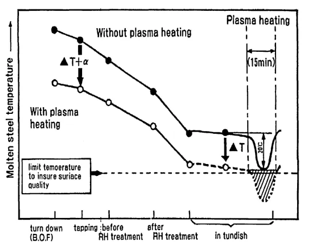
During operation, the temperature of molten steel is monitored continuously at a
location near the middle of the third zone. This temperature, together with selected
temperature and ladle conditions are entered into the computer to determine plasma
input power. Figure 2.8 shows actual results of temperature measurements; however,
using this method temperature control to within ±5°C was achieved.
Plasma heating
Without plasma heating
(15min)
a>
L_
3
+->
<0
k_
0)
Q.
E a>
■4—'
With plasma
heating
0)0)
c
0)
4-<
limit temoerature to insure suriace quality o
2
j after v
ftH treatm ent RH treatm ent in tundish turn down tapping :before
[image:48.616.144.448.377.613.2](b.o.f)
Chapter 2 - Literature survey
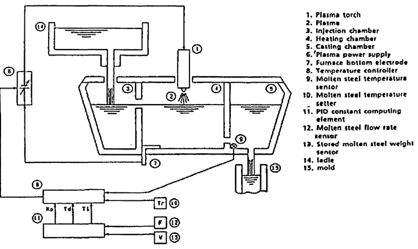
Mizushina et. al.[31] reported on the development of a 1.4 MW tundish plasma heating
system, where the temperature of the molten steel in the tundish could be maintained
to within ±1°C of the required steady state value using the control system, shown in
figure 2.9. The system is based on a computing unit which provides feedback so that
the molten steel temperature on the outlet side of the tundish heating chamber
corresponds to the present value of the desk-top set point station setter. The results obtained by using the plasma heating system have been a reduction on segregations due
to variations from the targeted superheat, and improvements in the reduction of
abnormal solidification patterns due to a drop in temperature during transient-state
operation. The required plasma heating power is set based on variations in the tapping temperature, therefore, reduction in the tapping temperature is possible, extending the
service life of the converter and increasing its heat allowance.
Moore et.al.[32,33,34] have also reported on the development, installation, uses and
advantages of the plasma heating systems in operation at the above steelmaking plants.
In order to control the tundish exit temperature reliably a system to monitor the input
temperature continuously needs to be developed as a basic element of the control
Chapter 2 - Literature survey
1. Plum* torch 2. Plum*
3. ln|ection ch»mbtr 4. H tilin g chim btr 5. Calling chamber fi.'Plasma power supply 7. Furnace bottom electrode 5. Temperature controller 9. Molten steel tem perature
senior
tO. Molten steel tem perature
„ setter
11. PIO constant computing elem ent
12. Molten it eel flow rate
tensor
13. Stored molten steel w e ig h t
Sensor 14. ladle 15. mold
Figure 2.9. Typical example of a temperature control system using plasma heating. (From Mizushina et.al. 1990)
2.5. CON
TI
NUOUS
T
EMPERA
TUR
E MEASUREMEN
T
OF
LIQUID S
T
EEL IN
T
HE
TU
NDISH.
In the steelmaking processes, liquid steel temperature is one of the basic indicators of
operation and quality control. The requirements for high quality steel have increased
dramatically, with more emphasis on superheat control and an ever increasing need for
better automation. Continuous temperature measurement in the tundish has become an
indispensable technology for the continuous casting process.
[image:50.615.88.497.85.329.2]Chapter 2 - Literature survey
The systems developed include immersion probes consisting of a either a classical
thermocouple protected by a ceramic tube or multiple thermocouple embedded in a
refractory section at varying displacements.
Choi and Mucciardi[35] developed a heat transfer model to monitor liquid steel
temperature continuously. The system is based on multiple thermocouple embedded in
a refractory section, the model analyzes the transient heat transfer behaviour started
once liquid steel is poured in the vessel in order to infer the temperature of liquid steel.
This mathematical model is based on the finite difference formulation of Fourier’s heat conduction equation. The refractory section was divided into discrete nodes to fulfil the
requirements of the finite difference technique. Then Fourier’s equation was applied to
each node, assuming one dimensional conditions.
The mathematical model was tested in a low temperature water model, and in a high
temperature laboratory experiments. Results showing actual measurements of bath
temperature were compared with computed bath temperature and were found to be in
good agrement.
Some steelmaking plants have developed continuous temperature devices which consist
basically in protecting the thermocouple with a ceramic insulator. Russo and Phillippi[36]
have used an alumina-graphite isopressed composite to protect a type B thermocouple
Chapter 2 - Literature survey
tundish campaign. At the end of each campaign the old protection tube is discarded and
the platinum thermocouple assembly is then reused with a new protection tube.
However, they report that premature failure of the protective tube can occur, slag
skulling being the main contributor.
P/C
Recorder
B/C
Pt/RhThermocouPle
00
2rB
2Protective tube
A
£20jProtective tube
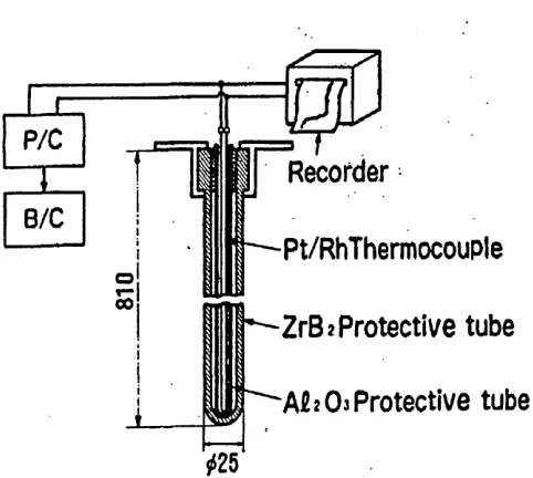
Figure 2.10. Construction of continuous measuring thermometer. (From Mori et.al. 1990)
Mori et.al.[37] developed a similar system, their research started by studying the
advanced ceramic to be used as the protective tube, various ceramics were selected,
tested by immersion into liquid steel, and evaluated for resistance to liquid steel and
slag. Zirconium diboride (ZrB2) was found to be the best suited.
The life of the continuous measuring thermometer is reported to be affected by
[image:52.615.173.414.199.415.2]Chapter 2 - Literature survey
number of times it is immersed and withdrawn. It measures the temperature of liquid
steel for an average of 40 hours and maximum of more than 100 hours during the
casting of carbon steel at Nippon Steel.
Similar continuous temperature measuring devices are reported to be in use in European
3
EXPERIMENTAL TECHNIQUES
3.1 DEVELOPMENT OF WATER MODEL SYSTEMS
The diversity of the fluid flow phenomena and the limitations of water as a modelling
fluid make it impossible to satisfy all of the requirements for similarity which apply to
fluid flow in a model of a given particular scale. Reynolds-Froude similarity requires
a full scale model. The Weber-Froude similarity requires a model of 0.6 scale. Some
numerical values for the applicable dimensionless groups are presented in chapter two,
table 2.2. It is important to determine to what extent similarity in the absolute sense is
necessary in modelling the actual system.
(a) Model design calculations
Heaslip et.al.[11] demonstrated that Froude number alone can be satisfied at any scale
in a tundish water model as long as all metering orifices and fluid hydraulic heads in
the system are sized in accordance with a single scaling parameter. This fortuitous
results arises as a consequence of the fact that all flows in the continuous casting system