Implementation of Running Average Background
Subtraction Algorithm in FPGA for Image Processing
Applications
S.Susrutha Babu
Assistant Professor Department of ECE
K L University Vaddeswaram, Guntur
S.Suparshya Babu
Assistant Professor Department of ECE
K L University Vaddeswaram, Guntur
ABSTRACT
In this paper a new background subtraction algorithm was developed to detect moving objects from a stable system in which visual surveillance plays a major role. Initially it was implemented in MATLAB. Among all existing algorithms running average algorithm was choosen because of low computational complexity which is the major parameter of time in VLSI. The concept of the background subtraction is to subtract the current image with respect to the reference image and compare it with to the certain threshold values. We propose a new real time background subtraction algorithm which was implemented with verilog hdl in order to detect moving objects accurately. Our method involves three important modules background modelling; adaptive threshold estimation and finally fore ground extraction. Compared to all existing algorithms our method having low power consumption and low resource utilization. Here we have written the core processor Microblaze is designed in VHDL (VHSIC hardware description language), implemented using XILINX ISE 8.1 Design suite the algorithm is written in system C Language and tested in SPARTAN-3 FPGA kit by interfacing a test circuit with the PC using the RS232 cable. Area and the speed of the algorithm are also evaluated.
KEYWORDS
Background Subtraction, Micro blaze, Object Detection, UART, VHDL.
1.
INTRODUCTION
Extracting moving objects from image sequences is fundamental problems in computer vision systems that are used in a variety of applications, such as video surveillance, human tracking, motion analysis and image synthesis .To detect the target, we use methods such as background subtraction [1], inter –frame difference and optical flow.
Frame difference method is highly adaptive to dynamic environments, but generally does a poor job of extracting the complete shapes of certain types of moving objects. Optical flow [6] is an approximation of the local image motion and specifies how much each image pixel moves between adjacent images. Optical flow is a very complex algorithm (it is necessary to store more than one image), requiring high memory resources and also it is hard to apply in real-time due to its high computational cost. In most of the cases, a stationary camera is used, which means that background subtraction techniques can be a power full tool for object detection. The simplest implementation of background subtraction is to evaluate the difference between a background image and current image in a pixel wise manner, and then thresholding the difference value to determine the pixels that belongs to moving objects. Common background subtraction methods include Running Average (RA) , Gaussian mixture model GMM) and nonparametric kernel methods[2]. Although GMM and nonparametric methods are stable algorithms their complexity makes it possible to be implemented by hardware approach. RA is also a stable algorithm, but its signal processing is more tractable for hardware implementation because of single modality in statistical modeling.
2.
THE REAL TIME BACKGROUND
SUBTRACTION DESIGN
This section first reviews the formulation of the Running Average algorithm. The Real time background subtraction improving the Running average algorithm by removing division operation is then described. Dataflow of the Real time background subtraction is also analyzed.
Review of Running Average Algorithm : The RA algorithm includes two steps: differencing step and background modeling step. The differencing step extracts motion pixels by computing the difference between current frame and
Dr.Habibulla Khan
Professor & Head Department of ECE
K L University Vaddeswaram, Guntur
M.Kalpana chowdary
M.Tech VLSI Student Department of ECE
background model. The background model is statistically built with single modality assumption.
The differencing step can be formulated as follows:
( ) = ( ) - ( ) | (1)
where ( ) is the pixel value of current frame at time t+1, ( ) is the background model at time t, and ( ) is the subtraction result. The background model of each pixel is assumed to be a single Gaussian, and its parameters can be recursively updated by new frame, which can improve computational efficiency and reduce memory resource allocation. The recursive form of expected value of the single Gaussian, ( ) , is described as follows:
= + (2)
where ( ) is the established background image at time t, and k is the learning parameter controlling learning speed of background. The difference image is then thresholded into by an adaptive threshold obtained by recursively updating the variance of the Gaussian model.
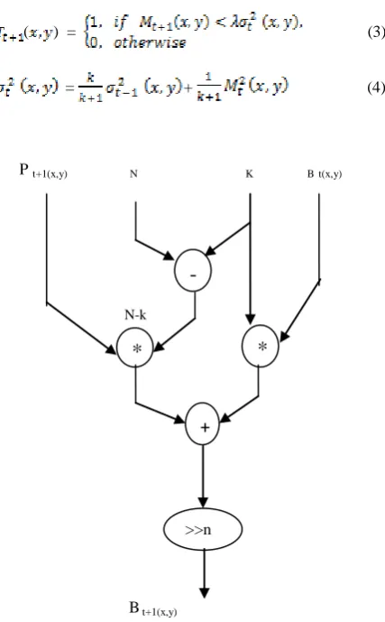
( ) = (3)
= + (4)
P t+1(x,y) N K Bt(x,y)
N-k
[image:2.595.353.517.228.500.2]B t+1(x,y)
Figure 1.Data flow diagram of the background modeling in Eq. (5)
where standard deviation is applied to the adaptive threshold and recursively updated by current frame. The parameter _ determines the desired precision of thresholding. The above formulation for background subtraction and
updating includes five multiplications, two divisions, and one radical expression operation. The divisions in Eqs. (2) and (4) require lots of logic circuit resources and can slow down computational performance. By applying integer arithmetic to replace division operation with bit shifting, we can greatly improve the hardware design of the RA algorithm.
In addition, the variance obtained in Eq. (4) has to be square-rooted into standard deviation for the thresholding in Eq. (3). The implicit radical expression needs to be eliminated. As a result, reformulation is necessary in order to shorten computational time as well as reduce resource utilization.
B t+1(x,y) P t+1(x,y) N K Vt (x,y)
N-k
V t+1(x,y) Figure 2.Data flow diagram of adaptive threshold
determination in Eq. (6)
B. The RTBS Algorithm
To apply shift circuit instead of division we have to modify the denominators of Eqs. (2) and (4). And we replace the with and substitute the in Eq. (3) with , where both sides of the condition have to be squared. The three new equations are given below:
= + , 0 < k < N, (5)
= + , 0 < k < N, (6)
( ) = (7)
where N is the m power of 2, i.e., N= . We replace the of RA with , and with .
--
*
-
*
*
+
>>
n
-
*
*
+
[image:2.595.59.273.335.680.2]
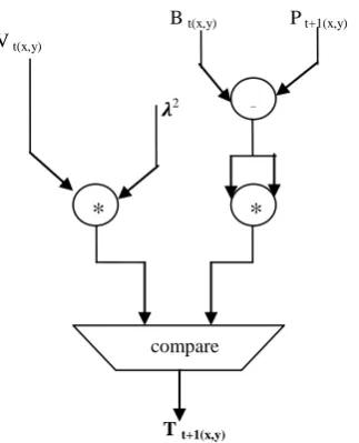
B t(x,y) P t+1(x,y) V t(x,y)
𝝀2
[image:3.595.90.252.90.290.2]T t+1(x,y)
Figure 3.Data flow diagram of the foreground extraction in Eq. (7)
As a result, we apply shift circuit to replacing division operations. Mathematically the reformulation produces residue between RA and RTBS on background updating. But we can demonstrate that practically the residue vanished as t increases. Before using Verilog for hardware design, we first analyze Eq. (5) with more details to identify the data flow of background updating. The data flow is shown in Fig. 1. Data flow of Eq. (6) to find adaptive threshold is shown as Fig. 2. Eq. (7) performs a new adaptive thresholding mechanism to find objects. Its dataflow diagram is shown in Fig. 3.
3. FLOW DIAGRAM FOR OBJECT
DETECTION IMPLEMENTED IN FPGA
In the first step we consider the video and convert it into frames, from that frames we can select any of two images for that two images we create a header file .And then we can write an algorithm for back ground subtraction in the XPS tool by using system „C‟ language. In the XPS we are giving two inputs of headerfile.h and source file.c. XPS is a tool used to link a program to hardware like FPGA. After downloading the bit stream open the visual basics application and click run button on the command window of XPS .Finally with the help of UART port and RS232 cable we made a communication between hard ware and our PC and we can see the output image in the PC with the help of visual bascis tool.
The Xilinx Platform Studio (XPS) is the development environment used for designing the hardware portion of our embedded processor system and Xilinx Embedded Development Kit (EDK) is an integrated software tool suite for developing embedded systems with Xilinx MicroBlaze and PowerPC CPUs. The Microprocessor Hardware Specification (MHS) file defines the hardware component. The MHS file serves as an input to the Platform Generator (Platgen) tool. The Microprocessor Software Specification (MSS) is used as an input file to the Library Generator (Libgen). The MSS file contains directives for customizing operating systems (OS), libraries, and drivers. The User Constraints File (UCF) specifies timing and placement constraints for the FPGA Design. The features of the visual
basics are Improved performance ,Visual data access with the data control so that it is possible to create data browsing application without writing code.
Headerfile.h
Source file.c
[image:3.595.318.557.127.445.2]
Fig 4: Flow diagram for FPGA implementation of object detection
4.
EXPERIMENTAL RESULTS
4.1 Tracking implemented in MATLAB GUI
MATLAB implements GUIs as figure windows containing various styles of uicontrol objects.GUI includes laying out the components, programming them to do specific things in response to user actions.GUIDE also generates an M-file that contains code to handle the initialization and launching of the GUI.
In this tracking first consider a small video and then separated into frames. After frame separation the object was detected, to remove the noise in the images we are using filters. The median filter[7] is normally used to reduce noise in an image. The median is a more robust average than the mean and so a single very unrepresentative pixel in a neighborhood will not affect the median value significantly. Since the median value must actually be the value of one of the pixels in the neighborhood, the median filter does not create new unrealistic pixel values. Thus the median filter is much better at preserving sharp edges than the mean filter.
*
-
*
compare
Consider two images from the video
Create headerfile for two images
Xilinx platform studio System C coding for Algorithm
Connect the Spartan 3 EDK board
Download bitstream and open visual basics
Fig 5: Tracking result implemented in GUI
4.2 object detection implemented in VHDL
The theoretical calculations were implemented by using running average algorithm to perform both differencing step and background modeling step after background modeling calculate the threshold value and compare the subtraction result with threshold value finally motion detected pixels are observed. For that the code was written in VHDL language and verify the output waveforms by using model sim tool.
Fig 6: Calculation of intensity values
Fig 7: background modeling
[image:4.595.50.287.69.265.2][image:4.595.315.577.82.279.2]
Fig 8: Adaptive threshold determination
Fig 9: Final motion detected pixel values
[image:4.595.350.538.544.746.2]Fig 10: RTL Schematic of Top module
Input video
Frame separation
Object detection
Filter
Fig 11: schematic of all individual modules
Table 1: Synthesis report of object detection implemented in Xilinx
4.2 Object Detection Implemented in Hardware
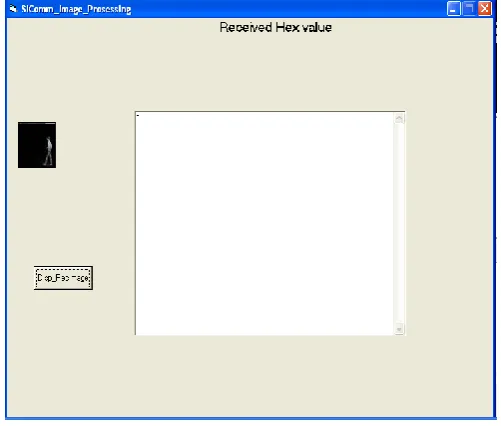
[image:5.595.313.564.73.286.2]The visual basics window appears in this manner in the right side the pixel values are moved one by one and after completion of all the pixel values the image was displayed on the right side of the window .
Fig 12: object detection output using visual basic
Table 2:Post synthesis report of the Algorithm is implemented in Micro blaze Processor
0 500 1000 1500 2000 2500 3000 3500 4000
slices slice flipflops
LUTS
Available Utilization
Fig 13: Area utilization
Device utilization summary
Logic Utilization
Used
Available
Utilization Number of Slices 409 4656 8% Number of Slice Flip-flops 269 9312 5%
Number of 4 input LUTS 269 9312 86%
Number of bonded IOBS 201 2312 86%
Number of MULT 18*18SIOs
16 20 80%
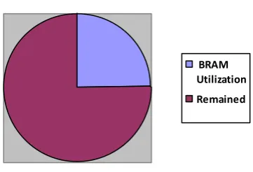
[image:5.595.309.557.73.764.2] [image:5.595.29.283.491.643.2]BRAM Utilization
Remained
Fig 14: Memory Utilization
Logic Utilization Used Available Utilization
Number of slices 1727 1920 89%
Number of slice Flip Flops 1805 3840 47%
Number of 4 input LUTS 2855 3849 74%
Number of Bonded IOBS 62 97 63% Number of DCM‟S 1 4 25% Number of BSCANs 1 1 100%
Number of BUFGMUXs 2 8 25%
Number of BRAMS 3 12 25%
[image:6.595.103.284.81.204.2] [image:6.595.49.286.218.415.2]
Table 3 : Device Utilization Summary in EDK
5.
APPLICATIONS
1.Automated video surveillance: In these applications computer vision system is designed to monitor the movements in an area, identify the moving objects and report any doubtful situation. The system needs to discriminate between natural entities and human, which require a good object tracking system.
2. Robot vision: In robot navigation, the steering system needs to identify different obstacles in the path to avoid collision. If the obstacles themselves are other moving objects then it calls for a real-time object tracking system.
3. Traffic monitoring: Traffic is continuously monitored using cameras. Any vehicle that breaks the traffic rules or is involved in other illegal act can be tracked down easily if the surveillance system is supported by an object tracking system. 4. Animation: Object tracking algorithm can also be extended for animation.
5. Magnetic Resonance Imaging (MRI): Doctors can get highly refined images of the body‟s interior without surgery. MRI is particular useful for imaging the brain and spine, as well as the soft tissues of joints and the interior of bones.
6.CONCLUSION
In this work a moving object detection based on running average algorithm was developed with a verilog HDL and also implemented on hardware. And the high cost function background modeling, is reformulated by eliminating division operations that can both reduce resource utilization and improve performance compared to all existing algorithms this can help in lowering execution times for high-resolution sequences.
7. REFERENCES
[1] S. Herrero and J. Besc`os. Background subtraction techniques: systematic evaluation and comparative analysis. International conferenve on Advanced Concepts for Intelligent Vision Systems, pages 33–42, 2009. [2] A Elgammal, D. Harwood, and L. Davis. Non-parametric
model for background subtraction. European Conference on Computer Vision, pages 751–767, 2000.
[3] Du-Ming Tsai and Shia-Chih Lai, Independent Component Analysis-Based Background Subtraction for Indoor Surveillance, IEEE Trans. on Image Processing, 2009, 18(1), 158-167.
[4] Francis R.B., and Michael I.J., Kernel Independent Component Analysis, Journal of Machine Learning Research, 2002, 3,1-48.
[5] Susrutha Babu Sukhavasi, Suparshya Babu Sukhavasi, “ Design of Modules to Implement a Structure by Discrete Reckoning Codes for Embedding Into Video Coding Testing Applications (IJMER), Vol.2, Issue.4, July-Aug 2012, pp-2867-2875 ISSN: 2249-6645.
[6] N. Lu, J.H. Wang, Q.H. Wu and L. Yang, “Motion detection based on accumulative optical flow and double background filtering,” Proceedings of World Congress on Engineering, London, UK, 2-4 July, 2007, pp. 602-607.
[7] Object Tracking and Detecting Based on Adaptive Background Subtraction by Ruolin Zhang, Jian Ding in 2012 International Workshop on Information and Electronics Engineering (IWIEE).
[8] Background subtraction techniques: a review 2004 IEEE International Conference on Systems, Man and Cybernetics.
[9] Comparative Study of Background Subtraction Algorithms by Y. Benezeth P.-M. Jodoin B. Emile H. Laurent C. Rosenberge.
[10] Chen Trista P, Hanssecker Horst, Bovyrin Alexander, Belenov Roman, Rodyushkin Konstantin, Kuranov Alexander, "Computer Vision Workload Analysis : Case Study of Video Surveillance Systems," Intel Technology Journal , vol. 9, no. 2, pp. 109-118, May 2005.