A Validation Frame Work Design Concept for Mutation
based Evaluation of Integrated Performance of Avionics
Systems of Unmanned Air Vehicles
Sudha Rani. S.V.
Scientist – ‘F’
Aeronautical Development Establishment Defence Research Development Organisation
Bangalore (India)
B. Ramadoss,
Ph.DProfessor, Dept. Of Computer Applications National Institute of Technology
Tiruchirappalli, Tamil Nadu (India)
ABSTRACT
The Avionics of an Unmanned Air Vehicle comprises of a number of Flight-Critical and Mission-Critical systems and a pilot-vehicle interface with complex real-time performance capabilities. Verification of integrated dynamic performance of such systems in an Avionics Integration Rig is a challenging task in terms of achieving sufficient test adequacy and inclusion of optimization in test case design. As the complexity of the systems increases, generating effective test cases to improve test adequacy and an optimistic way of classification of test case combinations becomes a necessity. This paper proposes a Validation Framework Design for Integrated Evaluation of Avionics Systems in a Rig with the introduction of various classifications of mutant operator models required for Mutation Testing, to achieve both the above factors required for evaluation of an Integrated Avionics System with respect to its System Level Specifications and Functional Performance.
General Terms
Integration, Simulation, Validation, Mutation
Keywords
Unmanned Air Vehicle, Avionics Systems, Avionics Integration Rig, Ground Control Station, Simulators, Mutant Operators, Line Replaceable Units, Test Case Generation, Mutation Testing, Test Adequacy, Mutation Analysis.
1.
INTRODUCTION
1.1
Avionics Systems
The Avionics Systems of an Unmanned Air Vehicle (UAV) comprise of a number of Air borne Systems such as Flight Control Systems, Data Link Telemetry Systems, Engine Instrumentation Systems, Navigation Systems, various Payloads and Mission Payload Interface Systems, Airborne Flight Data Recording System, etc., that are integrated through the various aircraft buses and other analog/digital interfaces. All these systems are complex hard real time systems which receive the commands and send on line responses to a Ground Control System (GCS) using a Data Link System during flight. The GCS has a pilot interface unit through which the pilot on ground commands the entire flight. Thus, the GCS sends commands to the aircraft, receives response, filters, and analyzes data from airborne computers in real time, and based on the data, it monitors the aircraft behavior and controls it. The airborne systems communicate with each other based on the command and control from the GCS and respond to the commands from GCS by packing the real-time data and
transmit the data streams to ground-based receiving stations via wireless channels in real-time.
The Integrated Performance of all these systems is verified in a Ground-Based Avionics Integration Rig. The Avionics Integration Rig comprises of GCS Simulator Models along with a number of Avionics Simulator Models. The Actual Systems/Line Replaceable Units (LRUs) are integrated in the Rig. The Rig has the capability to stimulate, simulate, monitor, record and analyze the data which transact between the LRUs or the Simulators (Models). The Rig has the capability to switch between the LRUs or their Equivalent Simulators. The different LRUs and the Simulators are all tested for their integrated functional behavior and communication with each other through various interfaces in terms of command and responses. Most of the LRUs are redundant in nature. Hence, the systems are also checked for performance of redundancy. The GCS and Avionics Simulators comprise of both Static generation-based models in which the inputs are defined in advance and stored in a repository and Dynamic generation-based models where, test data is generated in real time. A simulator simulates a LRU. It processes the data, establishes handshake and communicates the same to another model /LRU under test.
1.2
Necessity of Mutation Testing as part of
the Validation Framework
Most of the monitored data in the Rig demonstrates the behavior as per system requirements only. But, this is not adequate as it does not uncover the hidden defects of the system. To improve test adequacy, researchers have come out with various techniques, the most effective, being Mutation Testing. To execute this testing, operators called mutant operators which are different from the specified ones are inserted into the programs to produce versions called mutants. The general technique is called mutation or Mutant Generation. The process of analyzing when mutants fail and which of the test suites trigger such failures, is referred to as Mutation Analysis [1][2] the details of which are mentioned in Section 3.
2.
REVIEW OF LITERATURE
Ashutosh Kumar Jha, in his paper [3] discusses the development of a test automation framework for testing avionics systems at the unit, integration and system testing phases of the V-model system development life cycle. But this does not discuss any Mutation Testing Techniques to bring out the hidden defects in the system.
Grammar-based testing (code-level) and hence does not cover the testing at specification and integration level.
Later, mutation techniques used in verification of code have been extended by a number of researchers which are categorized as (a) Mutation for Timeliness [5][6][7] which explains the types of mutant operators as Execution time mutant operators, Lock time mutant operators, Unlock time operators in case of real-time systems, (b) Integration (Interface) Mutation [8][9][10], (c) Black-Box Mutation Testing (at a component level) [11]. Mutation-based simulation test data generation for testing complex real-time software has been proposed by Xiaying Bai, Shufang, Yinong Chen [12] with an application to space-borne systems. This paper discusses about mutant operator models w.r.t. Signal and Data Generators.
The work presented in the above papers has been studied. Some of the concepts mentioned in the above papers have been included in the Validation Frame Work Design Concept proposed in this paper, as an extension to their work. The Validation Frame Work Design has been proposed in this paper to improve test adequacy of Evaluation of Integrated Performance of Avionics Systems using an Avionics Integration Rig by the induction of various Mutant Operators, in addition to execution of normal test cases. These mutant operators are designed to verify specific functional requirements of the Avionics systems of an UAV. Using these mutant operators, minor changes are introduced in the specification/requirement level and given as inputs to the system and tested in addition to testing of required performance at real-time.
3.
MUTATION TESTING
3.1
Introduction
Mutation testing is an error-based testing adequacy criterion as stated by DeMillo [13], initially with the name “Mutation Analysis.” The first implementation of a mutation testing tool was by Timothy Budd [14] as part of his Ph.D. work (titled Mutation Analysis).
Mutation Testing consists of four steps: mutant generation; execution of the program P (or specification S) based on a defined test case set T; mutant execution; and adequacy analysis. All the mutants are executed using a given input test case set. If a mutant M presents results different from S, it is said to be dead or killed, otherwise, it is said to be alive. In the latter case, there is no test case in T that is capable to distinguish M from P (or S) or M and P (or S) are equivalent, in the sense that they have the same behaviour (or output) for any data of the input domain. The objective must be to find a test case set T able to kill all non-equivalent mutants; in this case T is considered adequate to test P (or S).
Through mutant simulation, a metric called the Mutation Score (MS) in Equation (1), measures the Test Set (T) quality with respect to a program P.
MS (T, P) = K / (M - E) (1)
where M is the number of generated mutants, K the number of killed mutants and E the number of equivalent mutants.
3.2
Mutation Adequacy
A set of test cases is mutation adequate, if its mutation score is 100%, which means that all mutants have been detected. This score is impractical in very complex real time systems, so the tester defines a “threshold” value, which is a minimum acceptable mutation score. If the threshold has not been reached, then the process is repeated, each time generating test
cases to target live mutants, until the threshold mutation score (about 85% to 90% : As empirical studies have shown that one can expect about 5% to 10% of the generated mutants to be equivalent to the parent program [15] is reached.
Budd and Gopal [16] found that it was possible to apply the concept of mutation analysis to specification based (box) testing. The proposal is to generate test cases by systematically replacing data-items relevant to a particular part of a specification with a data-item relevant to another. Rather than creating mutants from the program source code they are created by mutating the program specification. A mutation test set is then developed from the mutated specifications.
In this research, with an in-depth analysis of the fault pattern of the system under test, various mutant operators are defined for simulated test data generation. The test case design includes abnormal test inputs to be generated dynamically by utilizing the operators, as well as compositions of the operators, on the normal inputs. A test configuration is defined to organize and schedule the test execution.
3.3
Benefits of Mutation Testing
The mutant operators are very useful in the introduction of various types of faults, abnormal time, signal, clock and data transactions between the systems that can be simulated on ground. This helps in analyzing the integrated behavior where the conditions that the faulty outputs of one Avionics LRU can affect the other LRU during their integrated performance in flight. This also gives confidence about the recovery of the systems of the Avionics Systems under such circumstances (unexpected failures of the system) with the help of their fault-tolerant behavior. The sections of this paper are organized as follows. Section 4 details about the sub systems present in Rig and design aspects of Simulation System of the Avionics Integration Rig for an UAV. Section 5 brings out the aspects of design of Simulation System, categorizes the various mutant operators and their insertion in the Simulation System, modularity in design, independent verification and reuse. Section 6 focuses on the Actual Avionics Systems Mutation Based Evaluation in the Rig bring out the concept of using all the mutant operators individually, and also by their combinations using optimization techniques proposed by various authors. Section 7 gives the benefits of applications of this Frame Work. Section 8 finally concludes the paper with a discussion on effectiveness of the Validation Frame Work and future work which can be taken up in continuation with this discussion.
4.
AVIONICS INTEGRATION RIG,
SUBSYSTEMS AND DESIGN
ASPECTS OF SIMULATION SYSTEM
4.1
Major Sub Systems of the Integration
RIG
ii) Connection System– This system connects each of the LRUs and the corresponding simulation/stimulation models and is used for stimuli injection and response monitoring purposes. It enables switching between LRUs and models, enables breaking of signal path for inserting signal path failure (failure injection), switching between two or more LRUs if they are redundant systems, etc. It comprises of Test Panels to monitor the real-time signals during communication and Display Panels to display the various parameters received. It also consists of the Power Distribution Panel for distribution of power with proper circuit breakers, control of switch on/off of various systems including the redundant systems, breakout connectors, indicators for power supply monitoring on line and power on/off facility for each system. The Connection System also has display panels, other indicators, etc.
iii)Data Acquisition and Analysis System – This system monitors the real time data transactions and acquires the data for on-line and off-line analysis. Using this system, the post-flight analysis can also be carried out. The data is acquired from all the Simulators and LRUs by monitoring through the Connection System.
iv) Real-Time Testing Controller System- controls the entire system by sending the respective IDs for the test scripts based on the Users Selection of the LRUs, models and requirements, on the network to the Simulation System. It controls the entire Integration System as all the Simulators, the Data Acquisition and Analysis, Configuration Repository, etc. are clients on network.
v) Networking System-This is a network with a Client-Server configuration where the Real time testing controller system is configured as a server. On this network, the Configuration Repository, Simulation System, Data Acquisition and Monitoring System are connected. Thus, all the major systems in the Rig are networked for proper communication.
vi) Configuration Repository -This system is used as a System Storage and backup facility to configure with a proper version control, all the documents right from the specifications, test plans, test cases, monitored and acquired data, test and analysis reports, etc.
vii)Real-time Master Clock Pulse Generator -The Simulators, Data Acquisition and Analysis System are synchronized using a Reference Clock Pulse Generator.
viii) Power Distribution System – This system consists of Power Supplies and distributes power to LRUs and models systems installed in the Rig with protection and switching mechanisms and protection against high current. This is connected through the Connection System to the Simulators and LRUs.
ix) Test Equipment – This comprises of Signal Generator, Frequency Synthesizer, Multi Meter, Oscilloscope, etc.
x) LRU Bay – All Actual Avionics Systems such as Flight Control Systems, Data Link Systems, Payload Systems, etc. are placed in this Bay and connected.
The Rig performance is characterized by complex system interoperation, real-time data processing with stringent timing constraints and within acceptable latency, sampling and a large input domain.
4.2
Design Aspects for Simulation System in
the Rig
The Simulation System is the heart of the Avionics Integration Rig. The models of each of the Avionics Systems such as
Flight Control Systems, Engine Instrumentation System, Data Link Simulators, Payload Systems, etc. and GCS Simulators – Air Vehicle Simulators, Pilot Control Simulators, Payload Control Simulators, etc. are designed and developed as per their specific requirements. While designing each of the models, the following aspects for each model are considered:
4.2.1 Signal Generation for Data Transmission
(SG)
A signal is generated when the value of the sampling data changes to a certain extent, that is, the amplitude of the data sample reaches or exceeds the threshold and it keeps in the state for a period of time. Each signal has pre-defined rules for the condition, time, and frequency of its occurrence for various interface buses namely 1553B, RS422, Ethernet, Discrete, Digital, Analog I/O s, etc.
4.2.2 Command and Response Generation (CRG)
The required pilot commands sent from the GCS such as Navigation parameters such as roll, pitch, throttle, rudder, etc, Automatic Take Off and Landing commands, Engine related parameters, etc. and the responses expected from the corresponding Avionics System are generated by the Simulation System. The commands and responses are in the same category of the parameters.
4.2.3 Data Transmission (DT)
The required data forms the content of each protocol for each of the parameters above such as value, range, status, etc. is divided into packets as per the requirements and transmitted between GCS and the Airborne Avionics Models/Systems.
4.2.4 Interface Protocol Generation (IPG)
This configuration defines the data format, control, and operation information for the communication between the simulators and systems.
4.2.5 Real Time Clock Generation (Pulse
Generation (PG))
A real time clock is introduced in the system to synchronize all the systems, their timings with respect to their protocols, signals, etc.
5.
INSERTION OF MUTANT
OPERATORS (MO) IN THE
SIMULATION SYSTEM
5.1
Categorization of Mutant Operators
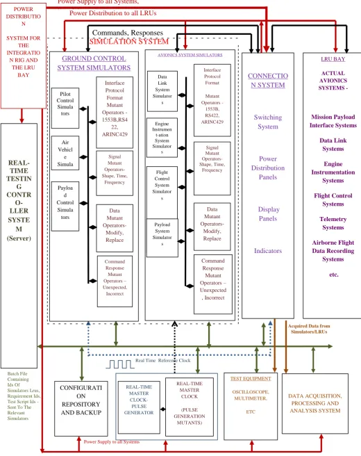
For each of the above aspects described in the previous section, separate mutant operators have been introduced as part of the Simulation System so as to form part of the models.These mutant operators are inserted and executed during stimulation of the models. Figure 1 shows the proposed Validation Framework concept of the Avionics Integration with the modular design of the various Mutant Operators as a subset of the Simulation System Design.
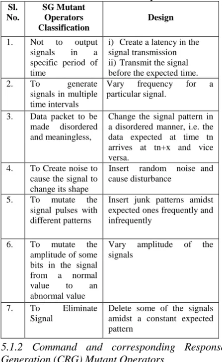
5.1.1 Signal Generation (SG) Mutant Operators
The signal generation mutant operators include signal elimination, timing sequence error, amplitude error, frequency error, persistence error, wave pattern error, noise disturbance, etc.
[image:4.595.314.521.70.156.2]5.1.1.1 Classification and Design
Table 1. SG Mutant Operators Sl.
No.
SG Mutant Operators Classification
Design
1. Not to output signals in a specific period of time
i) Create a latency in the signal transmission ii)Transmit the signal before the expected time. 2. To generate
signals in multiple time intervals
Vary frequency for a particular signal.
3. Data packet to be made disordered and meaningless,
Change the signal pattern in a disordered manner, i.e. the data expected at time tn arrives at tn+x and vice versa.
4. To Create noise to cause the signal to change its shape
Insert random noise and cause disturbance
5. To mutate the signal pulses with different patterns
Insert junk patterns amidst expected ones frequently and infrequently
6. To mutate the amplitude of some bits in the signal from a normal value to an abnormal value
Vary amplitude of the signals
7. To Eliminate Signal
Delete some of the signals amidst a constant expected pattern
5.1.2 Command and corresponding Response
Generation (CRG) Mutant Operators
The Command and corresponding Response generation mutant operators include incorrect command, incorrect response, correct command but response from another system, etc.
[image:4.595.53.277.164.528.2]5.1.2.1 Classification and Design
Table 2. CRG Mutant Operators Sl.
No.
CRG Mutant Operators Classificati
on
Design
1. To send an Invalid Command
Send Invalid Command i.e. for example, send a Navigation Command instead of an Engine command an expected system to an expected system 2. To send an
Invalid Response
Send Invalid Response to a Valid Command from an expected system to an expected system
3. To
Communica te with unexpected systems
i) Send commands to unexpected systems
ii) Send responses from unexpected systems
iii)Send valid command to expected one but response from an expected one and vice versa.
5.1.3 Data Transmission (DT) Mutant Operators
A Data Packet Generation mutant operator changes the normal data into an abnormal data following certain fault patterns. This set of operators modifies, replaces, and controls the transmission of data packets.
5.1.3.1 Classification and Design
These operators can be categorized as mutant operators which simulate the unstable generation of data packets such as even or uneven frequency irregularity occurrence.
Table 3. DT Mutant Operators Sl.
No.
DT Mutant Operators Classification
Design
1. To send in a sequence disorder
Send the data by changing the order of the bytes. 2. To insert data arrival
at a wrong time
Send data to a system at an unexpected time, i.e. the system is unaware about the action it has to take based on the arrived data.
3. To send a changed order of data such as circular left or right shift occurs,
Shift Right or Left by x and send the data
4. To send duplicated packets replacing the subsequent packets.
Introduce some junk data amidst the expected one.
5. To vary the
timestamp
Change the time stamp data value before the system actually receives it on the net.
6. To send modified length information,
Change the length of the data in terms of unexpected number of bytes
7. To send modified checksum
Send in correct checksum
8. To send incomplete data packet
Delete some of the bytes, make the data incomplete before the data arrives at the expected system. 6. To send extra data
packets in addition to the required data packets,
Send extra data packets than the required ones.
7. To replace normal data packets with an empty packet which has no data content, with the format and control information only
[image:4.595.53.259.583.762.2]5.1.4 Interface Protocol Generation (IPG) Mutant
Operators
These mutant operators deal with modifications with respect to the particular interface format in which the data is to be transmitted and received.
5.1.4.1 Classification and Design
[image:5.595.309.537.71.230.2]The data is transmitted using the mutated protocol interface and transmitted to the corresponding models/actual systems and response is analyzed.
Table 4. IPG Mutant Operators Sl.
No.
IPG Mutant Operators Classification
Design
1. To send an incorrect request protocol format
Send a command say, a complete Navigation Parameter Set of commands which is expected to be sent in a RS422 protocol, by using a 1553B format.
2. To send an incorrect response in corresponding protocol format
Send back the
corresponding response expected in an Ethernet format, by sending it in an RS422 protocol format. 3. To create error in
implementation of a particular protocol
Eliminate the
transmission of Status Word during a 1553B protocol transmission
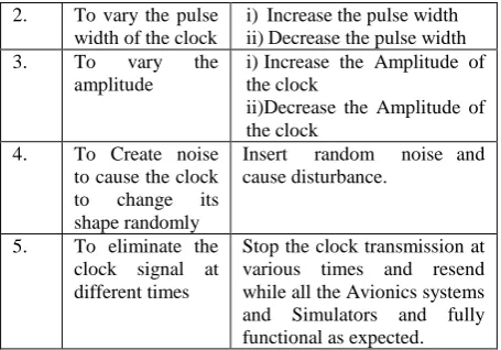
5.1.5 Pulse Generation (PG) Mutant Operators
Sometimes the Real Time Clock Frequency (Pulse Generation) which is used to synchronize all the systems itself may be incorrect. It needs to be tested as what frequency, pulse width, amplitude all the systems still get synchronized and behave as per requirements. Hence, the PG is varied with different pulse rates as a part of mutation testing to check the functionality of the systems synchronized at different clock rates.
5.1.5.1 Classification and Design
Table 5. PG Mutant Operators Sl.
No.
PG Mutant Operators Classification
Design
1. Not to send the Master Reference Clock to all systems at the specific
frequency.
i) Create a delay in the clock transmission
ii)Increase the clock frequency.
2. To vary the pulse width of the clock
i) Increase the pulse width ii)Decrease the pulse width 3. To vary the
amplitude
i)Increase the Amplitude of the clock
ii)Decrease the Amplitude of the clock
4. To Create noise to cause the clock to change its shape randomly
Insert random noise and cause disturbance.
5. To eliminate the clock signal at different times
Stop the clock transmission at various times and resend while all the Avionics systems and Simulators and fully functional as expected.
5.2
Implementation of Mutant Operators
All these above operators can be implemented by developing a user—friendly GUI based software to choose the type of categorization of Mutant Operators and within each categorization the respective type of mutation can be selected.The SG and PG operators can be implemented with a combination of hardware and software elements, to tamper with the output signals coming out of the interface cards in the Simulation System and developing a user—friendly GUI based software to choose the type of condition and introduction of the mutant operator. This can be achieved by usage of an Arbitrary Waveform Generator to control the signals and the Real Time Master Reference Clock which synchronizes the entire Avionics Rig. In these two particular cases, i.e., SG and PG, the mutant operators should be consciously chosen such that it will not damage the systems in the Rig, such as exceeding the voltage levels beyond acceptable limits.
A further stage of the design and implementation of the mutant operators also includes combined selection of various categories of the operators so that their combinatorial test design can be executed.
5.2.1 Modular Design of Mutant Operators
5.2.1.1 Separate files/packages for each group of
mutant operators
The insertion or removal of Mutant Operators should be in such a way as to not to effect the overall functioning of the Integration Rig, which in turn, should not affect the total certification of the Integration Rig. It is to be designed to behave as an independent entity which can be plugged in separately, updated independently and to be modular in nature. To achieve this, separate files/packages can be maintained for each group of mutant operators which do not affect the normal data and functionality testing of the systems. These mutant operator packages/files are to be verified separately.
Figure 1 - A Validation Frame Work Design Concept for Mutation Based Evaluation of Integrated Performance of Avionics Systems of an UAV in an Avionics Integration Rig
.
Acquired Data from Simulators/LRUs
REAL-TIME TESTIN
G CONTR
O- LLER SYSTE
M (Server)
Batch File Containing Ids Of Simulators Lrus, Requirement Ids, Test Script Ids - Sent To The Relevant Simulators
LRU BAY
ACTUAL AVIONICS SYSTEMS -
Mission Payload Interface Systems
Data Link Systems
Engine Instrumentation
Systems
Flight Control Systems
Telemetry Systems
Airborne Flight Data Recording
Systems
etc.
CONFIGURATI ON REPOSITORY AND BACKUP
REAL-TIME MASTER
CLOCK- PULSE GENERATOR
REAL-TIME MASTER
CLOCK
(PULSE GENERATION
MUTANTS)
CONNECTIO N SYSTEM
Switching System
Power Distribution
Panels
Display Panels
Indicators
TEST EQUIPMENT
OSCILLOSCOPE, MULTIMETER,
ETC
Commands, Responses
POWER DISTRIBUTIO
N SYSTEM FOR
THE INTEGRATIO
N RIG AND THE LRU
BAY
Power Supply to all Systems
Power Supply to all Systems, Simulators
Real Time Reference Clock
C
Power Distribution to all LRUs
DATA ACQUISITION, PROCESSING AND ANALYSIS SYSTEM
SIMULATION SYSTEM
AVIONICS SYSTEM SIMULATORS
AVIONICS SYSTEM ACTUAL SYSTEMS GROUND CONTROL
SYSTEM SIMULATORS
Data Mutant Operators-
Modify, Replace Signal Mutant Operators- Shape, Time,
Frequency Interface Protocol
Format Mutant Operators - 1553B,RS4
22, ARINC429
Interface Protocol Format
Mutant Operators -
1553B, RS422, ARINC429
Command Response Mutant Operators – Unexpected, Incorrect Pilot
Control Simula
tors
Air Vehicl
e Simula
tor Payloa
d Control
Simula tors
Command Response Mutant Operators – Unexpected
, Incorrect Signal Mutant Operators- Shape, Time,
Frequency
Data Mutant Operators-
Modify, Replace
Data Link System Simulator
s
Engine Instrumen
t-ation System Simulator
s
Flight Control System Simulator
s
Payload System Simulator
This has an advantage that any change in the mutant operators does not affect the rest of the system. This is a very important factor to be followed for obtaining Verification and formal certification by the Certification Authorities for the Mutant Operators in addition to the normal flow of communication as per requirements.
Model-checkers to verify mutation-based test-case generation, coverage analysis and specification analysis have been proposed by Gordon Fraser and Franz Wotawa [17].
5.2.3 Re-Use of Mutant Operators
The mutant operators can be classified as libraries and can be re-used and configured as libraries during Configuration Management. With the wide use and reuse of such black-box components such as reusable class libraries, minimum effort can be put while designing new categories of mutant operators during change management.
6.
MUTATION BASED EVALUATION
OF THE INTEGRATED AVIONICS
SYSTEMS IN RIG
The failure of any system in the aircraft can be caused by single or multiple factors, also multiple systems may fail due to a single factor. Hence design of test cases using combination of mutant operators which relate to each other is required to simulate such complex scenarios. In order to study and analyze the integrated effects of all the combinations of mutant operators, the test case design defines the association among the various simulator components, SG types, DT types, CRG types, IPG types, PG types respectively.
6.1
Test Case Design, Implementation and
Results using the above Mutant
Operators
Each of the above mutant operators is selected/de-selected in association with each of the relevant parameters from the Simulator Models and performance of the system is verified.
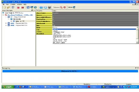
Implementation: A customized software named as Portable Avionics Test Solution using a Windows based Operating System has been used for simulation, mutant generation and acquisition for realization of some of the mutant operators.
IPG Mutant Operator: 1553B Error Mutant Generation
[image:7.595.321.543.80.221.2]Types of Errors which can be given in Figure 2 by User Selection such as Parity, Command-Sync, Data-Sync, Manchester-stuck-high, Manchester-stuck-low, Gap, Word-Count-High, Word-Count-Low, Bit-Word-Count-High, Busy Bit Set, Message Error, etc.
Figure 2. 1553B Errors Mutant Generation
[image:7.595.63.286.588.736.2]Parity Error: Results show Monitored data shows NR(No Response), PY (Parity Error) indications on the screen.(Figure 3).
Figure 3 Results display of Monitored Data indicating Errors
6.2
Test Case Design using Combination of
all the above Mutant Operators
System structure configuration shall be designed, so as to enable the re-composition of simulation segments by changing the associations among SG, DT, CRG, IPG, PG types and also the re-combination of different types of components for each segment.
However, conflict may exist when combining different operators. Adequate care is to be taken to avoid such test cases. For instance, (i) three operators, a combination such as a DT mutant operator with replacement of data packets with an empty packet with no data content, introduction of an IPG mutant operator with incorrect request protocol format from a system and an IPG mutant operator with incorrect response protocol format from the other system simultaneously (expected data is unpredictable) is invalid (ii) a SG mutant operator with multiple time intervals with a combination of a PG mutant operator such as no pulse generated (no real-time clock) (expected data is unpredictable) is also invalid
.
6.3
Optimistic way of grouping /
Classification of Test Case combinations
The test case design to implement all the above requires a large number of test cases. Hence, several techniques need to be designed to optimize the combination of test cases to improve test adequacy and to reduce time and effort. One way is, by classification of the mutant operators and their combinations using equivalence class partitioning technique as per their target fault patterns. This is done in various ways, i.e. one way :by classification of specifications to fall under particular ranges (categories/groups with a specific title) and design of common test cases for the group, another way to implement one full round of testing and categorize the test cases in terms of their outputs, and so on. Various techniques are been discussed by researchers regarding this.Higher Order Mutation Testing techniques [18][19]could be used in selection of the test criteria for more optimized, effective test cases and still achieve better test adequacy. Implementation of these techniques includes simultaneous execution of multiple mutant operators at the same time.
7.
BENEFITS
generated by mutant operators close to fault injection in addition to normal inputs.
ii) Enhance modeling capabilities by combination of normal and abnormal inputs.
iii)Enable powerful reuse and flexible adaptation to changes dynamically due to the modular approach in the design of the frame work.
iv) Enables exhaustive and systematic verification of Rig functionality during Regression Testing due to the modular design of the models.
In the past, a number of test cases were necessary to test real time embedded Avionics Systems and that too only based on specifications. By the proposed approach, with introduction of mutant operators and application of optimistic test case design and Higher Order Mutation Testing techniques, more exhaustive testing can be achieved with an optimistic design of combination of test cases because of the modular design of the models which enables reusability and modifiability and hence a better test adequacy could be achieved. Therefore, it greatly improves the effectiveness of testing, and saves effort and cost in designing, developing, generating, and executing the test cases. As a result, with proper grouping of the test categories and execution of the combinations of the groups, the testing time is considerably reduced to complete much ahead of the scheduled deadline along with the benefit of achievement of more confidence in the verification of the integrated performance of airborne systems.
8.
CONCLUSION
Test case and test data generation are key factors in effective real time simulation testing. The approach presented in this paper supports productive test case generation, based on the fault-driven test data from the definition of detailed categorized mutant operators and their valid combinations. The mutation introduced in the simulation system can be easily adaptive to changes because of the separate configuration file. In addition to achievement of improved test adequacy, the test optimization efficiency can be greatly improved with an intelligent classification-based selective testing method.
The paper discussed a general framework which can be applied in the validation of Avionics Systems of an aircraft. The various classified mutant operators could be realized as part of future work and their combinations and categorization into equivalence classes to be formed and the test results thus obtained by the above proposed framework could be checked for enhanced test adequacy by usage of lesser and more optimized test cases. Based on the results obtained from the above, comparative analysis w.r.t. existing techniques can be brought about in a graphical or tabulated form indicating the merits of the proposed Validation Framework Concept. Further, Automatic Test Case Generators could be designed to realize the same.
9.
REFERENCES
[1] Paul Amman, Jeff Offutt. 2008 – “Introduction to Software Testing" Cambridge University Press.
[2] Mathur .P. Aditya. 2008 - “Foundations of Software Testing”, Fundamentals Algorithms and Techniques, Pearson Education.
[3] Ashutosh Kumar Jha. 2010 - “Development of Test Automation Framework for Testing Avionics Systems” – 29th Digital Avionics Systems Conference
[4] Fevzi Belli, Mutlu Beyazit. 2010- “A Formal Framework for Mutation Testing” Fourth International Conference
on Secure Software Integration and Reliability Improvement.
[5] Robert Nilsson, Jeff Offutt, Sten F. Andler. 2004-“Mutation Based Testing Criteria for Timeliness” – Proceedings of the 28th Annual International Computer Software and Applications Conference (COMPSAC’04).
[6] Robert Nilsson, Jeff Offutt, Jonas Mellin. 2006 – “Test Case Generation for Mutation-based Testing of Timeliness” electronically published in Electronic Notes in Theoretical Computer Science.
[7] Robert Nilsson, Jeff Offutt. 2007 - “Automated Testing of Timeliness: A Case Study” – Second International Workshop on Automation of Software (AST’07).
[8] Marcio E. Delamaro, Jose C. Maldonado, Aditya .P. Mathur. April 1996 - “Integration Testing Using Interface Mutation” Technical Report SERC-TR169-P. Software Engineering Research Centre, Purdue University.
[9] Ying Jiang, Ying-Na Li1, Xiao-Dong Fu. 2010 - Faculty of Information Engineering and Automation “The Support of Interface Specifications in Black-box Components Testing” - Kunming University of Science - Fifth International Conference on Frontier of Computer Science and Technology.
[10]Shan-Shan Hou1,2, Lu Zhang1,2, Tao Xie3, Hong Mei1,2, Jia-Su Sun1. 2007 – “Applying Interface-Contract Mutation in Regression Testing of Component-Based Software” - IEEE.
[11]Tafline Murnane, Associate Professor Karl Reed. 2001 -On the Effectiveness of Mutation Analysis as a Black Box Testing Technique.
[12]Xiaoying Bai, Shufang Lee, Yinong Chen. 2007 - “Mutation-Based Simulation Test Data Generation for Testing Complex Real-Time Software” – Proceedings of the 40th Annual Simulation Symposium(ANSS’07) IEEE.
[13]DeMillo, R.A. 1983 - “Program Mutation: An Approach to Software Testing”. Technical report, Georgia Institute of Technology, Atlanta, GA.
[14]Timothy Alan Budd. May 1980 - ”Mutation Analysis of Program Test Data”. Ph.D dissertation, Yale University.
[15]Mathur .P. Aditya. Presentation during Fall 2007 updated on 23-12-2009.
[16]Budd, T.A., and A.S. Gopal.1985 - “Program testing by specification mutation” Computer Languages, 10 (1).
[17]Gordon Fraser and Franz Wotawa. 2006– “Using Model-Checkers for Mutation-Based Test-Case Generation, Coverage Analysis and Specification Analysis” - Proceedings of the International Conference on Software Engineering Advances (ICSEA'06) - IEEE.
[18]Mark Harman, Yue Jia and William B. Langdon. 2010 “A Manifesto for Higher Order Mutation Testing” - Third International Conference on Software Testing, Verification, and Validation Workshops.