GPRS Based HealthCare Telemonitoring System
J. Bennet Solomi
*, M. Rajalakshmi
**, C.V. Mala
***
Department of ECE, Einstein College of Engineering, Tirunelveli
**
Department of ECE, Einstein College of Engineering, Tirunelveli
*** Department of ECE, Einstein College of Engineering, Tirunelveli
Abstract- Every year 17 million people are died due to cardio vascular diseases. Some of the people life can be saved if immediate treatment will be given within the appropriate time. So the patient’s Cardiac health should be monitored continuously. A low cost hardware equipment has been designed and implemented to monitor the Body temperature, ECG signal, Blood Pressure and Blood Glucose of a patient. The major aim of this system is to provide an medical monitoring for the user at anytime , if there are any abnormal change of ECG data, body Temperature, Blood Pressure and Blood Glucose of a patient. Communication between client and server mobile phone is achieved through GPRS network. Temperature sensor LM 35 and electrodes are used to measure the body temperature and ECG signal of a patient and Pulse Oximeter is used to measure the Blood Glucose and BP of Patient. Body temperature ECG signal, Blood Pressure value and Blood Glucose value is transmitted as an email to the remote mobile phone.
Index Terms- ECG, BP, GPRS, EMAIL.
I. INTRODUCTION
ccording to a World Health Organization (WHO) estimate, cardiovascular disease kills almost seventeen million people around the globe each year with around twenty million people at a risk of sudden heart failure. Some of these lives can often be saved if prompt emergency care and cardiac surgery are provided within the so-called golden hour. Therefore, patients who are at risk require that their cardiac health to be monitored frequently whether they are indoors or outdoors so that emergency treatment can be given if problems arise . Telemedicine is widely considered to be part of the inevitable future of the modern practice of medicine. It is defined as the “use of advanced telecommunication technologies to exchange health information and provide health care services across geographic, time, social, and cultural barriers,” telemedicine is currently being used by doctors, hospitals, and other health care providers around the world . One of the important social problems we are facing now is the increasing percentage of the aged in the population Ageing of the world’s population is pervasive, profound and with advancing age, health status generally declines and, inducing an increasing need for chronic and geriatric care at home. On the other hand, modern people face much more financial and society pressure than before, living and working in a rapid rhythm, the health status can’t get often monitoring, sudden death occurs without any medical symptom. One solution to those problems is to develop and expand the precepts of home health care. One of the factors that will make home care successful is the use of
modern communication technology for information exchange between a home-bound patient or a office-working potential patient and the medical specialists providing care. Cardiac arrhythmia refers to any change from the normal beating of the heart. Abnormal heart rhythms can cause the heart to be less efficient, and can cause symptoms such as dizziness, fainting, or fatigue, even sudden death. Since they are sometimes very brief, it can be difficult to properly characterize them. Cardiac stress tests attempt to induce the event while the patient is wearing sensors in a laboratory. In a homecare system setting, wearable electrocardiogram sensors, body temperature sensor and Pulse Oximeter can give a continuously monitoring over days or weeks anywhere. The continuously recorded data is promptly sent to the physician for analysis.
II. PROPOSED SYSTEM
Initial research was conducted to determine the types of vital signs that are routinely measured during a visit to a doctor. These vital signs are: body temperature, ECG , blood pressure and blood glucose. Finally it was decided to build the sensors for measuring these vital signs. Using these sensors these vital signs can be automatically measured. Next, various technologies that were currently used to transfer these vital signs were examined and the most effective transmission Technology for this project was determined. The measured signals will be transmitted to the Remote Mobile phone using GPRS Network which has very high data rate.
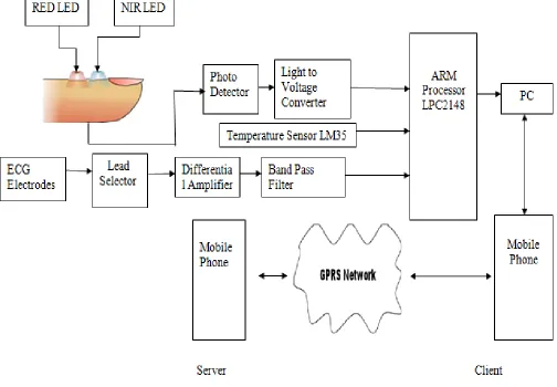
III. SYSTEM ARCHITECTURE
acquired data to the server unit by communicating with the GPRS network.
Figure 1: Tele monitoring System
A. The Client Unit
The client unit is comprised of vital-signs signals acquisition module and mobile phone. The core of the signal acquisition module is a ARM Processor LPC 2142 . The microcontroller acquires the amplified and conditioned signals, and then performs the interface with the mobile phone.
B.ECG Leads
The ECG is a graphical representation of electrical activities of the heart. The resulting heart dipole vector is used as a source for the ECG signal, which is the spatial sum in space of all distributed dipoles in cardiac tissue. A normal electrocardiogram with its characteristic patterns and significant points and intervals is shown in Figure 3. The amplitude of a QRS-complex is typically about ±1-2mV. We feed the signals from the three ECG electrodes Left Arm (AR), Right Arm (AR), and Right Leg (RL) into the inputs of the designed instrumentation amplifier conditioning circuit of an overall gain of 800. Also, the
signals are band pass filtered with a frequency range from 0.15-50 Hz.
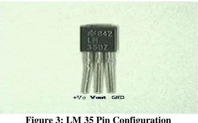
C. Body Temperature Sensor
Figure 3: LM 35 Pin Configuration
LM 35 has an output voltage that is proportional to the Celsius temperature. The scale factor is .01V/oC The LM35 does not require any external calibration or trimming.
D. Blood Pressure Measurement
For this project, the transmission technique is used on the finger to obtain the signal. In Transmission Technique the LED is placed on one side of the body and Photodiode is on other side. Red LED is used to measure the volume changes in blood. Using the Red LED light is passed through the finger and the photodiode captures the characteristics of the light transmitted through the finger and produces a current. The Red LED chosen for this project is 5mm, 2800 MCD, SSL-LX5093SRC/E that generates light with wavelengths of 660 nm. A light-to-voltage optical sensor, TSL250RLF is chosen to measure the light transmitted through the finger. Plethysmography measures the volume changes in an organ. Photoplethysmography is a plethysmograph obtained optically. PPG is obtained by a pulse oximeter. Light from a Light Emitting Diode (LED) is shone through the skin and changes in light absorption are measured through a photodiode. After obtaining the PPG, the Pulse Wave Transit Time (PWTT), the time between the R peak of the ECG waveform and the minimum point on the PPG waveform, is measured, A linear regression is then determined and systolic blood pressure is estimated from that relationship.
E. Blood Glucose Measurement
Near-infrared (NIR) diffuse reflectance spectroscopy involves the illumination of a spot on the body with low-energy NIR light (750–2500 nm). The light is partially absorbed and scattered, according to its interaction with chemical components within the tissue, before being reflected back to a detector. The detected light is used to create a graph of −log R/Rs, where R is the reflectance spectrum of the skin and Rs is the reflectance of the instrument calibrator. The prediction of blood glucose concentration is accomplished by detecting the magnitude of light attenuation caused by the absorption signature of blood glucose as represented in the targeted tissue volume of the skin. The process of calibration involves the development of a mathematical transformation or model, which is used to estimate the blood glucose concentration from the measured tissue absorbance spectrum.
F. ARM Processor-LPC 2142
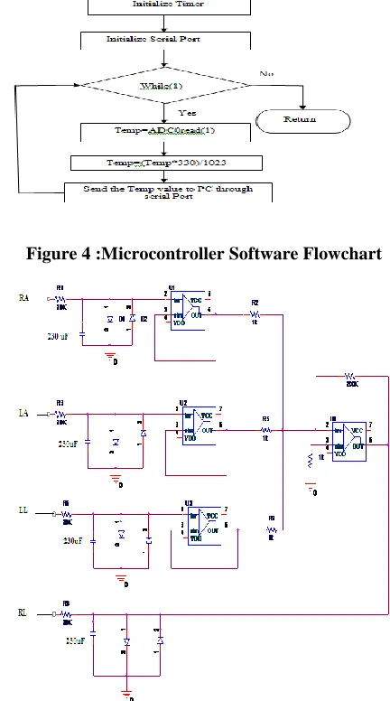
The is an 32-bit microcontroller LPC 2142, which has anon-chip 10-bit Analog-to-Digital Converter(ADC). The amplified and conditioned ECG signal is fed toADC0 of the microcontroller. Also, upon command, the microcontroller reads the temperature sample. It is then converted and stored in the LPC 2142 memory as two 8-bit unsigned integers (0-255). Then, sampling of the ECG signal is performed on channel-0 of ADC0 with a sampling interval of 8ms (125Hz). Samples are stored in buffers in memory for further processing. Figure 4 shows a flowchart of the microcontroller program. After completion of signals acquisition, the microcontroller constructs the SMS messages and packs the data samples in these messages to the desired length, then communicates with the mobile phone using at-commands on its RS232 port to send the message(s).LPC 2142 has 8 kB to 40 kB of on-chip static RAM and 32 kB to 512 kB of on-chip flash memory,128-bit wide interface/accelerator enables high-speed 60 MHz operation, In-System Programming/In-Application Programming (ISP/IAP) via on-chip boot loader software. Single flash sector or full on-chip erase in 400 ms and programming of 256 bytes in 1 ms. Embedded ICE RT and Embedded Trace interfaces offer real-time debugging.The LPC2142 contain one analog to digital Converter. These converters are single 10-bit successive approximation analog to digital converters. While ADC0 has six channels, ADC1 has eight channels. Therefore, total number of available ADC inputs for LPC2142 is 6.It has the following features:
1)10 bit successive approximation analog to digital converter.
2) Measurement range of 0 V to VREF (2.0 V ≤ VREF ≤ VDDA).
3) Each converter capable of performing more than 400,000 10-bit samples per second.
4) Every analog input has a dedicated result register to reduce interrupt overhead.
5) Burst conversion mode for single or multiple inputs. 6) Optional conversion on transition on input pin or timer match signal.
7) Global Start command for both converter
IV. METHODOLOGY
A. The Clip-on Type Electrodes
The clip-on type electrodes are attached to the patient’s body, after proper skin preparation with electrode jelly. The clip-on electrodes uses silver coated metal electrodes for proper skin contact and better signal pick-up. These electrodes are properly fastened to the patient’s body by the spring action of clip-on electrodes
B. Wilson Electrode
common mode rejection ratio of the overall system and reduces noise interference4. It also has the effect of reducing the current flow in to the right leg electrode. Increased concern for the safety aspect of electrical connection to the patient have caused modern ECG design to obtain the principle of ground reference altogether and use isolated or floating amplifiers5. The Wilson electrode is realized with the help of high slew rate FET output OP-Amps available in LM348 IC.
C. Analog Multiplexers
Analog multiplexers are used for lead selection in the place of mechanical rotary switches for smoother operation. These multiplexers can select the desired lead, which in turn is selected by the microcontroller. Since there are two multiplexers that are operated simultaneously two electrodes are selected one from each group. The output from this section is connected to the input of instrumentation amplifier.
D. Instrumentation Amplifier
The instrumentation amplifier is basically a differential amplifier that amplifies the difference between the two input signals. Hence the common mode signal is effectively eliminated. Two buffer amplifiers at the input of each signal, is provided to offer very high input impedance. The gain of the instrumentation amplifier is set around 1000.
E. Low Pass filter
The amplified ECG signal is passed through a low pass filter to remove the noise and other high frequency signal that might picked up by the cable etc. The pass band of this filter is set below 150 Hz. All the important components of ECG lies below 150 Hz6. The signal
from the low pass filter is further amplified using high gain amplifier.
F. Patient’s Isolation
The patient’s isolation stage is yet another important requirement due to safety of the patient. It uses an opto-coupler to transfer the processed E.C.G. signals to further stages, without electrical connection, i.e. through light beam modulation to carry signals. The patient is safe guarded against the risk of electric shock by having a optical coupler which transfer the ECG signals to further stage without electrical connection i.e. through light beam modulated to carry signals7. The ECG signal might be attenuated slightly in the opto-isolator.
G. Sample and Hold Circuits
Sample and hold is a circuit, which samples an input signal, and hold it to its last samplevalue until the input is sampled again. The purpose of sample and hold circuit is to sample fast changing signals and provide this signal as input to slow processing circuits like ADCs to match with its conversion time.
H. Analog to Digital Converter
The ADC 0808 or 0809 is an 8-bit A/D converter with 8- channel multiplexer. It is a monolithic CMOS devices of national semiconductor make. The A/D converter uses successive approximation as the conversion technique. It does not require
external zero (0) and full scales adjustments. There is no external terminal available.
I. Microcontroller
[image:4.612.341.534.198.354.2]The key feature of micro controller based system is that, it is possible to design a system with a great flexibility. It is possible to configure a system as large or as small system by adding or removing suitable peripherals. The micro controller has built-in ROM, RAM, parallel I/O, serial I/O, counters, interrupts and a clock oscillator circuit.
Figure 4 :Microcontroller Software Flowchart
[image:4.612.337.553.240.628.2]Figure 6: Circuit Diagram of ECG
[image:5.612.36.244.57.389.2]V. RESULTS
Figure 7: Hardware Implementation of Tele Monitoring System
Figure 7 shows the hardware implementation GPRS based Health care Tele Monitoring System which uses LM35 to
[image:5.612.311.533.93.309.2]measure body temperature, electrodes to monitor the ECG and pulse oximeter to measure the blood pressure and blood glucose.
Figure 8: Comparison of Filter Responses
Figure 8 shows the comparison of the responses of Band pass filter, Differentiator and Integrator. Band pass filter has better response.
[image:5.612.313.527.386.559.2]Figure 10: ECG signal received on Mobile Phone
Figure 10 shows the ECG waveform received on Mobile Phone. The application software was developed using the C++ programming language. Capturing the bio-signal , decoding them, and extracting the UD part is heart to this software.
VI. CONCLUSION
A low cost mobile patient monitoring system that utilizes Email was designed, developed, and tested. A body temperature sensor LM 35, a three lead ECG monitor (client unit) with a pulse oximeter on a cellular (mobile) phone platform, which can be considered as a realtime transmission mode. An application software is required at the receiving mobile device (consultation unit) to decode the biosignal email messages and plot the ECG and display the body temperature ,blood pressure and blood glucose values. The new system has a significantly reduced size and weight, which improves its versatility and mobility.
REFERENCES
[1] Ashraf A Tahat “Body Temperature and ECG Monitoring using SMS based Telemedicine System” IEEE 2009
[2] David Cuesta Frau, Manuel Varela, Mateo Aboy and Aau Miro- Martinez "Description of a portable Wireless Device for High- Frequency Body Temperature Acquisition and Analysis ”Sensor 2009 p.p7648-7663 [3] FANG Zu-xiang and LAI Da-kun “Uninterrupted ECG Mobile
Monitoring” IEEE 2007 Vol no.9 p.p33-34
[4] F Chiarugi ,D Trypakis ,V Kontogiannis ,PJ Lees “Continuous ECG Monitoring in the Management of Pre-Hospital Health Emergencies” IEEE 2003 P.P 205-208
[5] J.Reina Tosina, L.M.Roa, M.Prado,J.Vera “Home Health Telecare and the Elderly in Spain: Technologies Involved and Methodological Issues” IEEE 2001
[6] G.M. Patil, K. Subbarao, V.D. Mytricand A.D. Rajkumar "Embedded Microcontroller based digital Tele monitoring System for ECG"J .Instrum.soc.India P.P 134-149.
[7] S. Khoor, J. Nieberl, K. Fugedi and E.Kail "Internet based GPRS, Long-term ECG monitoring and non-Linear Heart rate analysis for Cardio vascular Telemedicine Management" IEEE 2003.
[8] Dr .P.K. Dash "ECG Monitoring "Indian Journal of Anaesthesia"August 2002 P.P 251-260.
[9] K.F. Tan ,K.L .Chan and K. Choi "Detection of QRS Complex, PWave and T Wave in Electrocardiogram" Department of Electronic Engineering ,City University of Hong Kong, Hong Kong.
AUTHORS
First Author – J.Bennet Solomi, M.E, Assistant Professor,
Einstein College of Engineering, [email protected]
Second Author – M.Rajalakshmi, M.E , Assistant Professor,
Einstein College of Engineering, [email protected]
Third Author – C.V. Mala, M.E , Assistant Professor, Einstein
College of Engineering, [email protected]
Correspondence Author – M.Rajalakshmi, M.E , Assistant