Computer Mouse using Eye Tracking System
based on Houghman Circle Detection Algorithm
with Grid Analysis
ABSTRACT
Large numbers of input devices are available for human interaction with modern computer systems which are operated by hands and a few of them through gestures made using fingers and body movements. The advancements in assistive technology have proposed many concepts for controlling the input and mouse movements by detecting the basic eye movements of a user with the help of the eye tracking systems. We place our focus on the implementation of the computer mouse which is designed to detect the relative position of the cornea with respect to the initially calibrated centre and calculate the attributes like angle and speed at which the movement of mouse cursor has to be initiated. The basic Houghman circle detection algorithm is used to process the incoming video frames to detect the cornea which lies in the centre of the pupil and the position of the cornea is compared with respect to the calibrated centre point with the help of a square grid on which an algorithm is applied to calculate the speed and angle at which the mouse should move with respect to x axis.
Index Terms – Eye operated, Mouse, Houghman Circle Detection, Grid, MATLAB, image processing, disabled, paralyzed
1.
INTRODUCTION
The computer mouse has gained very high popularity as an input device due to its simple to use mechanisms and accuracy of input. This popularity of the device started building up with the development of graphical user interface based operating systems like Microsoft Windows 95, SUSE, and Mandriva etc. The device transforms the relative movement of itself with respect to the base surface and inputs the two-dimensional coordinates to the device controller to initiate the cursor movement. The firing of any event or triggering an activity is commonly programmed to be carried out by detecting the mouse clicks which generates signals on pressing the mouse buttons.
However the main limitation of this device is the lack of usability for the people with disabilities including limb paralysis and those who lose their limbs in any accidents or poor development of body due to congenital defects. Such users face problems and inability to hold or moving the mouse as how normal users perform it. The eye tracking systems give them enhanced usability by tracking the eye movements to capture the details of relative position of the eye of the disabled users and use the information to move the mouse on the screen and help them use computers easily in spite of their disabilities. Various methods of eye tracking have been developed in which
camera and high precision monitor mounted telescopic cameras [1]. The camera detects the movement of the eye after the calibration process is performed successfully with few training sessions which records reference points given by the system. Once the training is completed, the system uses stored eye positions recorded during the training and current image of the eyes captured by live cameras to plot the expected position using linear interpolation methods. This method required efficient jitter reduction algorithm since the random movement of the user is quite common in practical cases [2]. Another algorithm was developed known as starburst technique which needed intensive reinforced learning for making the system practically reliable and the cost of implementation was too high[2]. The cameras employed to read the eye movements are highly sophisticated and involve huge investment thereby increasing the cost when production is adopted at a commercial level [2].
A very effective approach using usage of KNN classifier to determine various illumination conditions, which is more feasible than lighting compensation processing in real-time implementation. But this was very much dependant on the lighting conditions provided under practical environments and depended on the entire face image acquisition and extracting required features from the frame containing the image of whole face[3]. The extraction of the whole face as the problem domain makes it more complex since the image processing should involve segmentation process to separately isolate the properties of the user’s eye [7].
Another approach used in commercial scale is the sensing and picking up of the movement of the pupil and the reflected infrared light from the surface of the cornea which is considered as the reference point which was fixed. The hardware was embedded into a bezel of highly expensive computer monitors and the entire technical equipments would cost beyond the affordable limits for a commercial launch among common men. [4]. Many popular mouse system based on eye tracking generates no feedback on when person looks at it. It can be quite distracting to a person when he or she is aware of the gazes and consciously tries to put the efforts to control the location of the cursor on screen. [4]
2.
PROPOSED METHOD
The methodology used is based on the output of the implemented Houghman Transformation for circle detection to sense the image of the eyeball using a camera mounted on a headgear and continuously work upon the video frames to detect the relative position of the cornea with respect to pre calibrated centre point on a matrix to trigger the cursor movement across the screen. [5] The experimental setup has
Reji Mathews
Computer Science & Engineering Department, Amity School of Engineering & Technology,
Amity University, Noida, U.P
Nidhi Chandra
Computer Science & Engineering Department, Amity School of Engineering & Technology
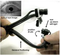
containing a simple webcam which captures the close up live video of the eye. An Eyelink [7] Toolbox in MATLAB enables experimenters to measure eye movements while simultaneously executing the stimulus presentation routines provided by the Psychophysics Toolbox and some of the controls in the toolbox aid the scaling of the captured image on to a virtual grid. The following figure [Fig 1] shows the photograph of the hardware device we have used for the experimental purpose. The device consists of a flexible structure which can be worn as a head gear by the user. The tip of the structure is mounted with a simple webcam which captures the image of the eye. An IR LED is used to illuminate the eyes and this method is technically known as dark-pupil illumination. The main reason for using this technique is the complete absorption of the IR rays into the cornea of the eyes so as to eliminate specular reflection caused when visible light is used instead[2]. This yields results with excellent accuracy by the image processing module we use to detect the center of the cornea to obtain its coordinates. The inlet shows the captured image on the computer screen. For better illumination, we have adjusted the position of the camera arm such that we have minimum blockage of the ambient light present in the laboratory and the shadow of the structure does not fall directly on the cornea.
Fig 1: The hardware device used for capturing the live video of the eye.
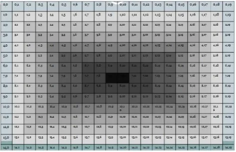
The calculation is facilitated by assuming an imaginary square grid placed over the input frames and detect the cell in the grid in which the centre of the eye is currently detected by Houghman’s circle detection algorithm. The direction of the cursor movement can be calculated by monitoring the coordinate of the cell inside the grid currently containing the detected centre of the cornea in live video stream input and the initially calibrated cell assumed to contain in the centre of the cornea while the used looks straight into the target and mouse movement is not expected and kept at rest.
There are two control parameters extracted from the input video for triggering mouse activities. The first parameter is the distance of the cell which contains the centre of the cornea from the live video input to cell in which the centre aligns itself when the user looks straight at the target. This is useful in estimating the speed at which the mouse pointer should be accelerated so as to avoid delays and lags which may annoy an impatient user. If the distance is more, the mouse pointer can be accelerated at a higher speed and in case it is very close, the speed can be reduced to a controllable measure so as to avoid rapid movements beyond the target.
[image:2.595.112.228.319.425.2]The second parameter is the position of the cell which correctly contains the centre of the cornea with respect to the last reported position of the cell which had contained the centre of the cornea.
Fig 2: Captured image of the eye is scaled across the virtual grid for processing and mouse movements.
This information is used to calculate the direction or angle at which the cursor must travel with respect to the horizontal axis to reach the new target where the user’s eyeball is aligned at
The process is divided into various stages. Initially the camera which is mounted on a specially designed head gear is placed very close to one of the eyes so as to capture the close up image of the eye ball to detect the slightest displacement of the cornea. An ambient source of illumination is provided inside the headgear between the eyes and the camera to avoid the darkness due to the shadow of camera on the eyes. We avoid a single point source of light like LED’s to avoid discomfort to the user. In our experiments, we have used a custom made circular shaped light emitting diode which distributes light evenly over the area. The image captured when an ambient source of illumination is fitted inside the headgear is shown below.
(a) (b)
Fig 3: (a) Image when the user looks straight at the object on screen when the face is also aligned such as the normal vector to the face passes through the object being gazed at. The mouse movement is not present in this case.
(b) Image captured through the camera when the user looks at object which does not lie in the vector normal to the fact. The mouse movement is triggered in this case.
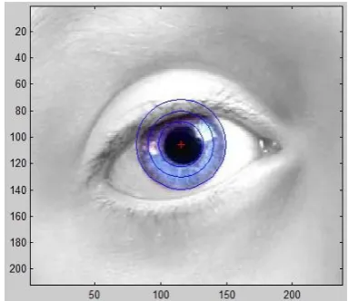
[image:2.595.313.540.447.553.2]In the proposed approach, the obtained sequence of frames is fed into the Houghman Circle Detection algorithm in order to detect the circular pattern of the cornea which makes it easy to spot the centre of the circle marking the exact position of the cornea. The specially designed image processing code take the input as the live captured frames and works on it by converting the image into grayscale and applying Houghman detection method to create a color distribution pattern in which the centre of cornea is highlighted by a color distribution shading which shows a slight convergence of the color pattern towards the point where the cornea is detected. [Fig 4] On the pattern, we can obtain the centre of the eye by applying point detection algorithms like Interest Point Detection Algorithm to return the coordinate of the centre of cornea. The program has been written using Houghman point detection for the process in MATLAB. The screenshot of the output of the program returns the x coordinates and y coordinates of the center of the eye.
Fig 4: Output of the Center detection program in MATLAB
Another method which can be considered is use of Hough circle algorithm which detects all the circles in the image and draws them in the accumulator variable. It was experimentally noted in the experiments that the circle with largest radius detected in the frame matched the boundary of the pupil. The other smaller circles were detected due to the incidental arcs detected by the eyelashes on the upper and lower eyelids. These circles were ignored by setting a threshold size of the circle radius which helped in filtering out smaller circles from processing. The accumulator variable stores the higher numerical value in the array with a color having brighter intensity as shown in the figure. [Fig 3]
The above process returns the coordinates of the cornea in the frames of the live video from the webcam. The next step in the process is to determine the current live location of the center detected with respect them to center point of the frame where the center resides when the user looks at the object keeping the face aligned to the object such that the normal vector to the face plane passes through the object. Consider the following virtual grid we have used to implement the cursor control system.
The cells in towards the inner part of the grid denotes the location where the cornea is detected when the user looks straight at the target location while the normal vector to the face also passes through the object being gazed at. When the cornea is detected at the core dark cells of the grid, the mouse movement is not moved at this point.
Fig: 5: The Virtual Grid – To be Mapped on video stream from Input Webcam
When the user moves his eyes outside this particular area, the image processing function returns the new coordinates of the center and the relative position of the new coordinate with respect to the center point are calculated which derives the equation of a line using the following formula.
Y-Y1 = [(Y2-Y1)/(X2-X1)]/(X-X1)
Equation 1: Equation for line joining 2 points (x1,y1) and (x2,y2)
This equation can be used to initiate the mouse movement from current point in the direction where the user gazes. The following algorithm can be used to perform the mouse movement
We assume an N by N square grid to be used in the process.
i. Repeat steps 2.1.2 to 2.1.4 while the cornea lies outside the center region of the grid. (denotes active mouse movement) ii. Obtain the equation of the line in the form y= m x + c by
using the coordinates at the center of the grid (x0,y0) and current detected coordinate of the center of the eye (xd,yd) and substituting in the equation shown in figure 2.4. iii. Keep initial coordinates (x0, y0) as (N/2, N/2)
iv. Calculate value y0,y1, y2, y3… by substituting values for x1,x2,x3 into the line equation calculated in step 2.2 using values between (x0 and xd) and simultaneously move the cursor to position [(x1,y1), (x2,y2), (x3,y3) …..( xd,yd)]
We have used an alternative method for moving the mouse cursor apart from the above algorithm which proves to be more efficient in terms of computation complexity. As discussed earlier, the obtained equation denotes the line which passes through the center calibrated point of the grid and the point at which the center of the cornea currently resides. From this equation we derive the slope of the line with the another geometrical formula stated below
m = [(y2-y1)/(x2-x1)]
Equation 2: Equation for calculating the slope of the line.
makes the easier implementation of our logic since it employs the use of reusable components already available.
3.
IMPLEMENTATION & RESULTS
The Image processing was simulated in the MATLAB and the Houghman circle detection algorithm was used to process the image from the live camera to obtain the coordinates of the center of the eye which was then used to calculate which cell in the grid contained the center. The image processing part was performed with the machine with standard Pentium III processor clocked at 2.0 GHz equipped with 4 MB cache memory, 256 MB RAM and standard on board graphic processing unit of Intel motherboard.
[image:4.595.73.265.271.437.2]The algorithm returned the image of the eye with a circle drawn with a red colored cross hair printed at the center. The screenshot is shown below.
Fig 6: The output of image processing function returning the cornea with a red crosshair at the center
The Houghman algorithm returned the 3-D view of the accumulator variable along with the coordinate of the center in a running time of 0.32 seconds. The screenshot of the MATLAB program is found below.
(a)
(b)
Fig: 7: (a) the 3-D view of accumulator variable with center being shown as peak of highest intensity (b) The accumulator variable shown in 2 D form with the center of cornea represented by higher intensity color values.
The detected center of coordinate of the eye is scaled into the virtual grid of the pre decided dimensions N X N. In our experimental labs we have taken the 28 X 30 grid for the simulation. The center zones of the grid was defined to be constituted by the cell (14,14), (15,14), (16,14), (15,14),(15,15),(15,16),(16,14),(16,15), and (16,16).
When the input video frames were scaled with respect to 28 X 30 grids, if the detected center of the eye was found in any of the above cells, it kept the mouse at the resting position. No movement of the cursor was performed in this state. When the center of the coordinate went to grid cells apart from those in the center zone defined above, the mouse movement was performed successfully with the trigonometric calculation discussed in section 2.
The jittery mouse movement was overcome using this approach unlike this in the studied eye tracking mouse solutions studied during the research.
4.
CONCLUSION
[image:4.595.55.271.531.716.2]5.
FUTURE WORKS
The implemented system is observed to have huge potential for use in other eye operated devices for the disabled. The future works will be aimed at modifying the approach to make it suitable for use in the eye operated wheelchairs. The wheel chair control system can be controlled using the signals generated by the system working on the discussed logic and can further reduce the cost of the expensive solutions and increase comfort for the users who are in need of the same.
6.
ACKNOWLEDGEMENTS
I would like to express heartfelt gratitude towards my faculty guide Mrs. Nidhi Chandra, Faculty, Computer Science & Engineering Department, Amity University for her guidance and help in completing this work successfully with good results. I would also like to express my gratitude to my Head of the Department Prof .Dr (Col) Kaiser Singh for his timely support and help.
7.
REFERENCES
[1] ANAELIS SESIN, MALEK ADJOUADI, MELVIN AYALA, ARMANDO BARRETO, NAPHTALI RISHE "Effective Data Conversion Algorithm for Real-Time Vision Based Human Computer Interface" Proceedings of the 6th WSEAS Int. Conf. on Software Engineering, Parallel and Distributed Systems,Corfu Island, Greece, February 16-19, 2007
[2] Dongheng Li, David Winfield, Derrick J. Parkhurst "Starburst: A hybrid algorithm for video-based eye tracking combining feature-based and model-based approaches"
[3] Yuan-Pin Lin, 1 Yi-Ping Chao, 2 Chung-Chih Lin, and 1 Jyh-Horng Chen "Webcam Mouse Using Face and Eye Tracking in Various Illumination Environments" Proceedings of the 2005 IEEE Engineering in Medicine and Biology 27th Annual Conference Shanghai, China, September 1-4,2005
[4] Web Reference -Ref: http://www.technologyreview.in/ computing/18254/
[5] Web reference – URL ref: http://www.jasonbabcock.com/ eyetracking_hardware.html
[6] FRANS W. CORNELISSEN and ENNO M. PETERS "The Eyelink Toolbox: Eye tracking with MATLAB and the Psychophysics Toolbox" Behavior Research Methods, Instruments, & Computers 2002, 34 (4), 613-617
[7] FRANS W. CORNELISSEN and ENNO M. PETERS "The Eyelink Toolbox: Eye tracking with MATLAB and the Psychophysics Toolbox" Behavior Research Methods, Instruments, & Computers 2002, 34 (4), 613-617