FPGA and dSPACE based Sliding Mode Control of Boost
Converter for PEM Fuel Cell Application
Bharti Kumari
P. G. Student Instrumentation and ControlC.O.E. Pune
Ravindra S. Rana
P. G. Student Instrumentation and ControlC.O.E. Pune
C. Y. Patil
Associate Professor Instrumentation and ControlC.O.E. Pune
ABSTRACT
This paper presents a non-linear dynamic model of a PEM (Proton Exchange Membrane) fuel cell and its simulation in MATLAB. A single cell and three cells stack is fabricated and simulation results obtained are validated experimentally with the dynamic response of the system for change in values of different system parameters. To meet the varying requirements of the load, boost converter circuit is designed and classical PID as well as advanced sliding mode control strategies are simulated in MATLAB and implemented using FPGA (Field Programmable Gate Array) and d-SPACE for experimental validation.
Keywords
Boost converter, d-SPACE, FPGA, PEM fuel cell, PID, SMC
1.
INTRODUCTION
The present era of energy crisis and exponential increase in ecological imbalance due to the unregulated exploitation of non-renewable resources has led to a serious shift towards developing renewable sources as PEM Fuel cells to meet the need of the hour.
In spite of being a potential candidate, many factors associated with fuel cell application still prevent its commercialization. The high capital cost of fuel cell based electricity generation system due to high cost of fuel, catalyst, components etc, complex BOP (Balance of Plant) requirements, custom designed power conditioning unit, high operating and maintenance cost, sophisticated and advanced controller requirements to control the non-linearity of cell has limited its growth and development.
The major cost incurred for advance controllers, their design and implementation can be reduced by using embedded development platforms such as FPGA and d-SPACE. These platforms avail us with high processing speed, accuracy, flexibility in designing, re-configurability, easy peripheral hardware interfacing.
The state-space model developed in [2, 4] based on [1] aims at developing a control oriented model for a 500 W, 48 cell stack and its validation against the experimental results of [1]. Further, [3] and [5] attempts to model an overall PEM fuel cell distributed system and its control along with its power conditioning unit. Suitability analysis of different topologies of power converters for fuel cell application is done in [6]. A hybrid fuel cell-battery control and d-SPACE based hardware implementation of [7] and FPGA platform usage in [8, 9] reveal the utility of these platforms for developing and testing different control algorithms.
Major contribution of this paper is towards hardware implementation of boost converter and its classical PID
(Proportional Integral Derivative) as well as advanced SMC control implementation. Simulation and analysis of the dynamic model of a PEM fuel cell and boost converter systems are done in Matlab whereas, PID and sliding mode voltage control design for boost converter and its implementation is done using dSPACE and FPGA platforms. A comparative analysis of implementation of PID and Sliding mode voltage controller on RTI 1104 R&D board and Virtex-5 FPGA has also been done.
Section II involves modeling of the fuel cell and power conditioning unit element, which is followed by the control design for the boost converter in section III. Section IV consists of simulation of the developed model and the control strategies. Hardware of the system, for testing the developed control strategy is explained in Section V. The results of the experiment are presented in section VI and finally the conclusion is given in Section VII.
2.
MODELLING
In order to design a control for a system, we can have a model which imitates the system as closely as possible in lieu of the actual system. The model is tested for satisfying response for the control strategy and extended further to the actual hardware of the system. The dynamic behavior of the PEM fuel cell and boost converter fed from it is modeled in this section, which is used further for control design.
2.1 PEM Fuel Cell Model
PEM fuel cell is an electrochemical device which generates electricity from the chemical reaction of the species called the fuel (oxidizing species at anode liberate free electrons) and the oxidant (reducing species at cathode accept free electrons) to produce water. The electrons liberated at the anode by the oxidizing species are made to flow through the external circuit, which constitute the current, by making the electrolyte (a polymer membrane) impermeable to electrons, but permeable to the protons. The electrons from the external circuit and protons passing through the electrolyte react at the cathode to form water.
Anode oxidation : Cathode reduction : Overall cell reaction :
2.1.1
Steady State Model
The reversible single cell potential ( ) generated by a single cell is governed by the Nernst equation as [2]:
(√ )
Where, the variables are referred in Appendix. is standard cell potential obtained in ideal conditions at STP, without considering the following practical losses occurring due to loading:
1. Activation Losses ( )
2. Ohmic Losses ( ) 3. Concentration Losses ( )
These losses are given by the following equations [1, 2]:
) (2) ) (3)
(4)
Thus the net open-circuit voltage output ( ) for unit cell is given by:
) (5)
2.1.2
Dynamic Model
As the reaction progresses with time the parameters of the system are no longer constant but dynamic. The rate of change of parameters with respect to time is formulated, from the laws of conservation of mass, energy and other basic sciences which makes it possible to determine the value of parameter at any given instant of time for given initial conditions. The main fuel cell parameters: temperature, pressure, flow and humidity are considered here for dynamic analysis.
2.1.3
Flow Dynamics
Applying molar balance to individual species we have, the net molar flow rates of hydrogen, oxygen and water as [2]:
( )
) )
(6)
( )
) ) (7)
( )
) ) (8)
2.1.4
Pressure Dynamics
Application of ideal gas law, based on the assumption of ideal gas behavior gives the rate determining equations for the partial pressure of the reacting species [2]:
(9)
(10)
(11)
Where, are as in [2].
2.1.5
Temperature Dynamics
From [1, 2] and [5] the net heat generation in the system is the sum of all the heat generated minus the total heat lost from the system. Heat is generated in PEM fuel cell only due to the electrochemical reaction ( ̇ ) occurring, but heat losses
occur from the system due to convective heat transfer of air ( ̇ ), heat lost due to the electrical ohmic losses ( ̇ ) and heat removed from the system by the coolant ( ̇ ), in case
of cooling provided. Temperature dynamics, thus can be modeled as [2]:
̇ (12)
̇ ̇ ̇ ̇ ̇ (13) Assuming no cooling in the system,
̇ ̇ ̇
(14)
Where the rate of heat generation due to electrochemical reaction is directly related to the rate of reaction taking place and is given as:
̇ (15)
The heat generated due to electrical output power is a function of voltage and current of the cell and is given as:
̇ (16)
Heat lost due to convection is a result of the difference in the temperature of the ambient environment and the cell:
̇ ) (17)
Where, are as in [2].
2.1.6
Boost Converter Model
Fig 1: Boost Converter Circuit
Using state–space averaging method dc-dc boost converter can be modeled as [6, 10]:
̇ ) () ( )
(18)
̇ ) ( ) ( ) (19)
Where, equation variables are as labeled in Fig 1. is the current from the fuel cell input ( ) to the boost converter and
is its output to load voltage.
3.
BOOST CONVERTER CONTROL
3.1
PID Control
It is the simplest classical control which utilizes a feedback loop to generate error (e). It uses a combination of proportional, integral and derivative action to process the error and produce optimum control (u) given as:
3.2
Sliding Mode Control
Boost converter being a variable structure system, where, switching over changes the structure of the system, sliding mode control is the most suitable control strategy for such systems. The low sensitivity of the sliding mode approach to the system parameters variations and disturbances makes the control robust.
[image:3.595.323.536.76.242.2]The rate of change of inductor current being higher than the output voltage rate of change, according to the theory of singular perturbations [10] the control is designed by using a cascaded inner current control loop and an outer voltage control loop using the integrator back-stepping method or regular form control. Usually, voltage control is achieved with standard linear control techniques, whereas the current control is implemented using PWM. Hardware implementation of a sliding mode control is much easier than a PWM control due to high frequency operation of switching elements.
Fig 2: Sliding Mode control strategy for boost converter
With the control objective to achieve a constant output voltage ( ), equal to reference, the steady-state behavior would be as:
(23)
̇ ̇ (24) Control input of voltage controller generates the desired current ( ), it is the value of the current which meets the reference voltage ( ) as:
(25)
For enforcing sliding surface ( ) to achieve current control is as:
(26)
and the control ( ) designed to achieve sliding (enforcing to track )is:
( ) ) (27)
The discontinuous control of SMC has its own limitations as it can cause excessive wear and tear of actuators, chattering in controlled output and may excite un-modeled dynamics.
4.
SIMULATION
4.1
Matlab Simulations
4.1.1
Fuel Cell Simulation
Developed models for the fuel cell and the boost converter are simulated in Matlab/Simulink. The simulation parameters for fuel cell model are taken from [2] for the Avista Labs SR-12 PEM fuel cell stack and the results are validated with the experimental results presented in [1].
Fig 3:Simulink model of fuel cell
4.1.2
Boost Converter Simulation
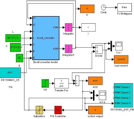
[image:3.595.60.274.299.376.2]Open –loop boost converter model is simulated in Simulink using SimPower Systems toolbox Power Electronics elements.
Fig 4: Simulink Model of Boost Converter
4.2
dSPACE Simulations and Real Time
Implementation
4.2.1
PID controller
Closed-loop control of boost converter using its state–space model equations, is designed for voltage loop. The error signal is given to the PID controller which generates the control signal ‘u’. This control signal is used to control the duty cycle of the PWM pulses to for driving the MOSFET of the boost converter.
[image:3.595.322.538.299.418.2] [image:3.595.320.534.557.748.2]4.2.2
Sliding mode controller
[image:4.595.318.538.114.293.2]Sliding mode control strategy utilizes cascaded current and voltage control loop, which generates the PWM control signal ‘u’. The control signal has been implemented in the real time by dSPACE DS1104 board, through the mathematical environment of Matlab/Simulink. In case of SMC the control is designed to generate the PWM signal.
Fig 6: dSPACE based SMC control of boost converter
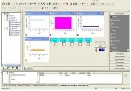
[image:4.595.60.275.169.331.2]The Control Desk software enables us to design user-friendly displays for monitoring and changing the parameters of the control loops online, saving the time of running the program every time a parameter is changed. Here we can monitor the output voltage, current switching surface and control signal for SMC.
Fig 7: dSPACE Control Desk Display for SMC control
4.3
FPGA hardware-co Simulations
FPGA is a special class of ASICs which offer cost reduction and improvement of control performance in designing a controller by prototyping and behavioral synthesis on the FPGA. FPGA gives faster performance as operations are done in parallel. Minimum resource utilization in FPGA, helps to reduce computation time and hence takes less time to generate the control action.
System Generator is used to design the Proportional, Integral and derivative action of the PID controller. The state (capacitor voltage) is being compared with the reference
[image:4.595.319.537.375.575.2]voltage to generate the error signal. The error is then given to the PID controller designed in System Generator to give control output ‘u’ to the boost converter system.
Fig 8: FPGA based PID control of boost converter
The SMC control designed in section III is implemented on FPGA Virtex-5 platform and hardware - co simulation of the controller is done in System Generator environment. The results of which is presented in Fig 7-10.
Fig 9: FPGA based SMC control of boost converter
5.
Hardware Implementation
[image:4.595.58.278.446.599.2]Fig 10: dSPACE hardware implementation
[image:5.595.334.521.76.256.2]On dSPACE DS1104 board the channel 5 of ADC is used for giving the input to the converter and control input is taken out from the PWM slot of ST2PWM for PID control implementation. The control output of the SMC being PWM pulse, is directly taken out from the pin 1 and 2 of Digital I/O slot for PWM and ground respectively.
Fig 11: dSPACE board input and output
6.
Results and Discussion
6.1
PID Control of Boost Converter
[image:5.595.57.280.396.547.2]PID control of boost converter provide satisfactory results for proper tuning of the gains values. For a reference voltage of 40 V, it shows gradual and smooth rise to the reference value. It can be seen that current also attains its corresponding steady-state value but at a faster rate. Thus, the response of the current is faster when compared to voltage and hence we use current in the inner cascade loop of SMC. The control output from the PID controller is used to generate the PWM signal to be fed to the MOSFET.
Fig 12: PID controller boost converter output voltage and current
6.2
SMC Control of Boost Converter
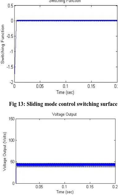
For the same reference voltage and system parameter values, SMC control shows, chattering around the reference values of voltage and current. The switching function value reaches to zero, making the inductor current trace the desired current value which meets the corresponding voltage reference and chatters over the sliding surface. The control signal is designed as a function ofswitching surface which turns theswitching element ON/OFF to trace the reference value.
Fig 13: Sliding mode control switching surface
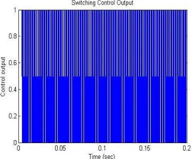
[image:5.595.326.520.417.580.2] [image:5.595.326.517.421.736.2]Fig 15: Sliding mode boost converter output current
Fig 16: Sliding mode controller output
[image:6.595.65.261.72.226.2]Table 1 shows the resource utilization for implementation of conventional PID controller and sliding mode controller on Viertex-5 FPGA platform. Table 2 shows comparison of resources used for implementation. As can be seen clearly SMC utilizes lesser resources for implementation and hence is easier for hardware implementation.
TABLE I
Resources utilization for PID and SMC controllers on Virtex-5 FPGA
S. No Devices PID SMC
1 DSP48Es (128) 27 0
2 Slice LUT- Flip Flop pairs (44800)
1077 661
3 Slice LUTs (44800) 772 500
4 Route-thrus (89,600) 121 100
TABLE 2 Synthesis report
S. No. Devices PID SMC
1 Multipliers 6 1
2 Adder 5 1
3 Registers 76 bit 18 (76 bit) 4 (32-bit)
4 X-or 27 5
5 Inverter 0 1
6 Comparator 0 1
7.
CONCLUSION
Fuel cell is a complex system to be modeled and controlled to deliver continuous varying load at its output. In a combined system of Boost converter and fuel cell, the boost converter comparatively, can be more easily controlled to deliver a regulated output to the load. Utilization of development platforms of FPGA and dSPACE enables easy design and efficient utilization of resources for implementing control algorithms.
8.
ACKNOWLEDGMENT
The authors would like to acknowledge the support extended by NCL, PUNE for providing the fuel cell experimental data for model validation.
9.
REFERENCES
[1] C. Wang, M. H. Nehrir, and S. R. Shaw, “Dynamic Models and Model Validation for PEM fuel cells using electrical circuits, ”IEEE Trans. Energy Conversion, vol. 20, no. 2, pp. 442–451, Jun. 2005
[2] Sachin V. Puranik, Ali Keyhani and Farshad Khorrami, ”State-Space Modeling of Proton Exchange Membrane Fuel Cell ”IEEE Trans. Energy Conversion, vol. 25, no. 3, Sep.2010
[3] C.Wang, M. H. Nehrir, and H. Gao, “Control of PEM fuel cell distributed generation systems, ”IEEE Trans. Energy Conversion vol.21, no. 2, pp. 586–595,Jun 2006.
[4] L.Y. Chiu, B. Diong, and R. S. Gemmen, “An improved small-signal model of the dynamic behavior of PEM fuel cells,” IEEE Trans.
[5] “PEM Fuel Cell Distributed Generation System: Modeling and Robust Nonlinear Control” Joint 48th IEEE Conference on Decision and Control and 28th Chinese Control Conference Shanghai, P.R. China, December 16-18, 2009
[6] “A COMPARATIVE STUDY OF DC–DC CONVERTERS’ EFFECTS ON THE OUTPUT CHARACTERISTICS OF DIRECT ETHANOL FUEL CELLS AND NiCd BATTERIES” by FLORIAN MISOC
[7] Control Algorithm of Fuel Cell and Batteries for Distributed Generation System Phatiphat Thounthong, St´ephane Ra¨el, and Bernard Davat, Member, IEEE
[image:6.595.68.261.280.440.2]Sadhana Kumari,Under the guidance of Prof. Kamalakanta Mahapatra
[9] K. Petrinec, M. Cirstea, K. Seare, C. Marinescu “A Novel FPGA Fuel Cell System Controller Design”. 11th International conference on Optimization of Electrical and Electronic Equipmen,2008, pp. 401-406.
[10]V. Utkin, J. Guldner, and J.X. Shi, Sliding Mode Control in Electromechanical Systems, London, U.K.: Taylor and Francis, 1999
[11]“Sliding Mode Control of Boost Converter: Application to energy storage system via supercapacitors” Hijazi Alaa, Di Loreto Michael, Bideaux Eric, Venet Pascal, Clerc Guy, Rojat Gerard published in "EPE, Barcelone : Spain (2009)"
10.
Appendix
Table1. Fuel Cell Simulation Parameters
Parameters Symbol Value
Ideal gas constant R
8.314 472 J K−1 mol−1
Faraday’s Constant
Temperature
F
T
96,485 C /mol
( in Kelvin)
Load inductance
Load resistance
15 mH
5.55Ω
Standard voltage 1.23V
Activation loss constants
1.3697V
-0.00308
Ohmic loss constants
0.0033 Ω
-
Limiting current 0.0333 A
Convective heat
transfer coefficient hs 37.5 W/( )
Area of single cell As 0.032
Specific heat capacity Cfc 500 J/(molK)
Mass of fuel cell Mfc 44 Kg
Flow delay at anode
Flow delay at cathode
60 sec
Anode Cathode
channel pressure -
Ambient temperature -
Partial pressure of x -
Net molar flow rate of
x )