Digital Code Lock using ATMEGA 328 AVR
Micocontroller
Surendra Yadav1, Akshat Yadav2, Anupam Yadav3, Anchal tyagi4 1, 2, 3, 4
Electronics and Communication Engineering Department, ABES Institute of Technology, Ghaziabad, Uttar Pradesh, India
Abstract: In this current situation, the degree of security is feeble. So there is a lot of robbery, theft going on in and around the world. So, people fear to keep any of their valuables in their homes. Hence many people prefer to keep it in banks. However, in this insecure world even banks are not too safe enough to satisfy people needs. A common man feels his valuables are secured if there is efficiency in security. Hence this project can give effective security in minimal cost. Index-Terms: Arduino, Relay, LCD 16x2, 4Membrane Keypad, Buzzer.
Keywords: Atmega 328 Avr microcontroller, LCD, Regulated power supply, LED, Buzzer, Relay
I. INTRODUCTION
In this project we are providing enough security to satisfy the user’s needs. Ex: mobile phones, office, home etc. The user will be prompted to enter a password to unlock the door. On successful password entry, the door unlocks for a specified amount of time enabling him/her to store or restore his/her valuables.
On the other hand, if the user enters an invalid password then corresponding equivalent message will be displayed. This project “Arduino based password protected locking system” can be used to provide enough security in various places like bank lockers, security doors, BIOS locking in computer etc. This project uses an arduino kit that consists of ATmega 328 which is one of the most popular microcontrollers that consists of 14 digital pins and 6 analog general purpose pins, EEPROM of capacity 1KB and a ram of 2KB.
II. COMPONENT DESCRIPTION
A. Atmega 328 AVR Microcontroller
It has 28 pin and in this project we use only 20 pin of micro controller .Atmega 328 microcontroller contains 32 kB flash memory ,2kB SRAM,1kB EEPROM and maximum operating frequency 20 MHZ.In this types of microcontroller there are 23 general purpose input output lines. It also a popular microcontroller.
Figure1: Atmega 328 Avr microcontroller Pin Diagram This image
cannot currently be display ed.
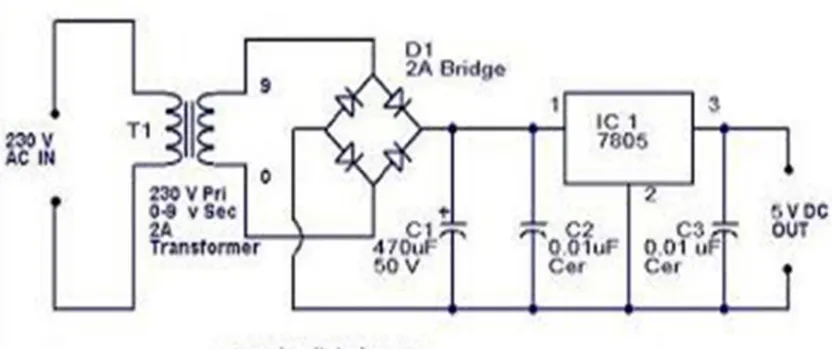
B. Regulated Power Supply
To drive Microcontroller & discrete component circuit we need regulated power supply. Here we have design 5V regulated power supply using LM7805 Regulator. Which can step down 12V AC/DC source to constant 5V by using rectifiers & filters. For rectification we have use 1N4007 diode as bridge rectifier & after that we have connected 1000uf/16V electrolytic capacitor as charge storage capacitor to fed constant voltage to regulator. After that regulator is connected with 100nf capacitor, which work as filter means it pass block DC & pass AC. So, if any AC component reaches their than it will ground that signal & protect regulator from being damage. After regulator Same electrolytic capacitor is used to store charge.
Figure2: Regulated power supply
C. Relay
[image:3.612.108.524.184.359.2]A relay is an electrically operated switch. Many relays use an electromagnet to mechanically operate a switch, but other operating principles are also used, such as solid-state relays. Relays are used where it is necessary to control a circuit by a separate low-power signal, or where several circuits must be controlled by one signal.
Figure 3: Relay
III. WORKING AND CIRCUIT DIAGRAM
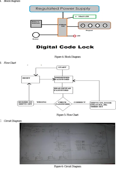
A. Block Diagram
Figure 4: Block Diagram
B. Flow Chart
Figure 5: Flow Chart
[image:4.612.44.495.79.748.2]C. Circuit Diagram
IV. EXPERIMENTAL RESULTS
Our project are working properly in both hardware and software .In this project we are providing enough security to satisfy the user’s needs for ex-home safety ,office etc. The user will be prompted to enter a password to unlock the door. On successful password entry, the door unlocks for a specified amount of time enabling him/her to store or restore his/her valuables.
V. FUTURE SCOPE AND CONCLUSION
A. Future Scope
In future we can add multiple security option and sensor to enhance feature of this digital lock .Ex.
1) Rfid: Code lock+ RFID so user has to punch first card & than has to enter right password
2) GSM: during accessing of device this device will send message to owner of device so if there is any unauthorized access than
owner can known by sms alert.
B. Conclusion
Our project work accordingly as we want successfully manner. Someproblem are arisen when we were connecting microcontroller
to hardware of project. By using four button we can free up more pin of microcontroller. By using thumb sensor and biometric sensor etc. We can make digital code lock more smarter .
VI. ACKNOWLEGEMENT
We would like to take liberty to thanks Ms. Anchal Tyagi and our friends for constant support and motivation during the completion of this research paper. We also thanks to all faculty member of our “Electronics and Communication Engineering Departments” and our friends for guide to make research paper.
REFERENCES [1] AT mega 328P datasheet http://www.atmel.com/Images/doc8161.pdf.
[2] Jeremy Blum ,” Exploring Arduino: Tools and Techniques for Engineering Wizardry”, Wiley publishers,4th edition(2004).
[3] LCD 16*2 datasheet http://www.engineersgarage.com/electronic-components/16x2-lcd-module-datasheet.http://www.instructables.com/id/Password-Lock-with-Arduino/
[4] Annie P. Oommen1, Rahul A P2, Pranav V3, Ponni S4, Renjith Nadeshan5,”Design and Implementation of a Digital CodeLock”International Journal of Advanced Research in Electrical, Electronics and Instrumentation Engineering (An ISO 3297:2007 Certified Organization), Vol. 3, Issue 2, February 2014 [5] Jeremy Blum ,” Exploring Arduino: Tools and Techniques for Engineering Wizardry”, Wiley publishers,4th edition(2004)
[6] Prakash Kumar, Pradeep Kumar, “Arduino Based WirelessIntrusion Detection Using IR Sensor and GSM”, InternationalJournal of Computer Science and Mobile Computing, Vol. 2,Issue. 5, May 2013, pg.417 – 424