© 2017, IRJET | Impact Factor value: 5.181 | ISO 9001:2008 Certified Journal | Page 1186
Progressive Collapse Analysis of Low Rise Steel Frame Structure With
and Without Bracing System
Krishna Kant Chaubey
1, A.B.Pujari
2, Dr. Venkata Dilip Kumar P
31 Krishna Kant Chaubey, Postgraduate student, KJ College of Engineering, Pisoli, Pune, Maharashtra.
2 A.B.Pujari, Professor, KJ College of Engineering, Pisoli, Pune, Maharashtra.
3 Associate Professor, School of civil engineering,Anurag group of institutions, Hyderabad.
---***---Abstract -
Progressive Collapse is a local failure of aprimary structural component leads to collapse of adjoining member which leads to additional collapse. Hence the total damage is disproportionate to the original cause. The most common local failure is framed structural is to be column failure. This paper compares the influences of several modelling approach for progressive collapse assessment of steel frame structure, considering sudden column loss as design scenario. A linear static analysis based on the GSA-2013 guidelines is used as preliminary study to determine progressive collapse analysis of low rise steel frame structure with and without bracing system. In this study, a column at the different position and different story level is removed to simulate an effect of an extreme event and the remaining structure is analysed using a finite element software ETABS 2015. The structure is analysed for gravity load and seismic load. Then the structure is checked for the Demand Capacity Ratio as per GSA 2013.
Key Words
: Progressive Collapse, Demand Capacity
Ratio, GSA-2013, Steel structure failure, ETABS 2015
etc.
1. INTRODUCTION
Progressive collapse is a catastrophic structural phenomenon that can occur because of human-made or natural hazards. In progressive collapse mechanism, a single local failure may cause a significant deformation which may then lead to collapse of a structure. If a structure has good alternative loading path, the initial failure will not expand to the other parts of the structure and the local damage will be restricted. The American Society of Civil Engineering (ASCE, 2005) is the only mainstream standard which addresses the issue of progressive collapse in some detail. The guidelines for progressive collapse resistant design are noticeable in US Government documents, General Service Administration (GSA, 2003) and Unified Facility Criteria (UFC, 2009). The GSA guidelines have provided a methodology to diminish the progressive collapse potential in structures based on Alternate Path Method (APM). It defines scenarios in which one of the building’s columns is removed and the damaged structure is analysed to study the system responses. The UFC methodology, on the other hand, is a performance-based
design approach, and is partly based on the GSA provisions. GSA Guidelines the General Service Administration (GSA) analysis includes removal of one column at a time from the storey 1 above the ground floor. GSA provides criteria for column removal for static analysis case. According to that a column is removed as mentioned below for typical structures. Exterior Column in the middle of longer side of building Exterior column in the middle of shorter side of the building Corner Column but in the present study the building considered is a typical structure and has an irregular/asymmetric plan and bay size. Hence GSA suggests, an engineering judgment is to be done along with the above mentioned column removal cases and additional critical locations for removing column for analysis are to be decided.
1.1 Sub Heading 1
Before you begin to format your paper, first write and save the content as a separate text file. Keep your text and graphic files separate until after the text has been formatted and styled. Do not use hard tabs, and limit use of hard returns to only one return at the end of a paragraph. Do not add any kind of pagination anywhere in the paper. Do not number text heads-the template will do that for you.
Finally, complete content and organizational editing before formatting. Please take note of the following items when proofreading spelling and grammar:
2
.
Literature Review:-
© 2017, IRJET | Impact Factor value: 5.181 | ISO 9001:2008 Certified Journal | Page 1187
Pinteaa(2012) made an attempt to investigate and evaluatedof multi-storey moment-resisting steel frames with stiffness irregularities using standard and advanced pushover methods. The results show that the adaptive pushover methods give the best approximation in terms of medium and maximum errors of the interstory drifts. [2] Khandelwal ,K; EL-Tawail, S;and F.(2009) studied on progressive collapse analysis of seismically designed steel braced frames and performed a research for evaluating the progressive collapse of steel braced frame through using models based on validating computational simulation procedures through applying alternative path method (APM). They conducted their standard on a ten story building by removing important load bearing column and adjacent braces in order to define the ability of the structure to resist the member loss. They finally concluded that the frame that was braced eccentrically was a more resistant to progressive collapse than that was braced concentrically.[3] H.R.Tavakoli and A.Rashidi Alashti (2012) made an attempt to investigate and study whether MRF steel structures that have been designed based on seismic codes, are able to resist progressive collapse with damaged columns in different locations under seismic loading. For this purpose, 3-D and 2-D push-over analysis of structures is carried out. This conclusion is reached without taking into consideration the beneficial effect of slab action. The panel zone in girder to column joints was assumed to be rigid, and connection properties were not considered. Although lumped plastic hinges can appear to provide a good solution to the modeling problem, they actually only shift the difficulty elsewhere, by raising the question relative to the numerical length of the hinge.[4] Kamel Sayed Kandil, Ehab Abd El Fattah Ellobody and Hanady Eldehemy(2013) studied and Experimental Investigation of Progressive Collapse of Steel Frames and two new tests conducted to augment available data highlighting the structural performance of multistory steel frames under progressive collapse. The comparison between the experimental results and the existing results in the literature with finite element results obtained in this study showed that the developed model simulates the behavior of steel frames well. It showed that the maximum lateral deflection measured for the edge-column-removed case was higher than that when predicted numerically because the fixation points of the steel frame were not fully rigid. It also showed that the column adjacent to the removed column underwent higher strains than other columns, which implied the redistribution of forces from the removed column to the nearest columns [5].
3. Research objective:-
A significant portion of the reported collapse includes progressive collapse that often leads to large human and property losses. In order to reduce the potential of progressive collapse, detailed behavior of a structural system is needed when a structural member is damaged.
To find out the critical locations of the three dimensional low rise (G+5 & G+10) moment resisting frame.
To find out detailed behavior of a structural system when a structural member is damaged.
Capturing realistic structural response of three dimensional structures using various analyses. Considering sudden column loss as a design scenario.
Aim is to make such building which should be progressive collapse free.
4. Research methodology:-
In this study a framework of low rise steel structure 5th and 10th story for progressive collapse, considering sudden loss of column as a design scenario and the structure analysis to minimize the collapse by using ‘V’ bracing at each outer face of structure by using software .The steel frame structure analyzed using Finite Element software ETABS-2015 the linear static response with dynamic effects in a simple method are carried out. The resisting capacity of moment resisting frame using alternate path methods for progressive collapse as per recommended in the GSA-2013 guidelines. The linear static and Non-linear static analysis procedure were carried out for comparison of basic model, removal of column at different location at different floor with bracing and without bracing. It was observed that in the linear static analysis progressive collapse of steel frame structure were minimized by using ‘V’ bracing at outer face of frame structure. Also it is observed that the non-linear static analysis provided larger structural responses and the results varied more significantly as comparison to linear static analysis. However, the linear procedure provided a more conservative decision for progressive collapse potential of model frame structures. GSA stated DCR criteria for acceptance of member,
DCR=Qud/Qce Eqn. 1
Model Description
© 2017, IRJET | Impact Factor value: 5.181 | ISO 9001:2008 Certified Journal | Page 1188
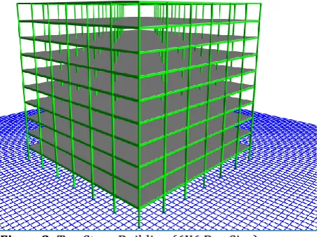
Figure 1: Five Story Building. (6X6 Bay Size)Figure2: Ten Story Building (6X6 Bay Size)
Loading cases:-
All loading cases are used according to GSA 2013 guideline for Progressive Collapse.
For Linear Static
Increased Gravity Loads for Floor Areas above Removed Column or Wall,
After removal of Column,
Glf = ΩLF [1.2DL+ (0.5LL)] Eqn. 2
Gravity Loads for Floor Areas Away From Removed Column or Wall Before removal of Column:
Glf = 1.2DL+ (0.5LL) Eqn. 3
For Nonlinear Static
Increased Gravity Loads for Floor Areas above Removed Column or Wall,
After removal of Column,
Glf = Ωn [1.2DL+(0.5LL) Eqn. 4 Gravity Loads for Floor Areas Away From Removed Column or Wall Before removal of Column,
Ωn = 1.08+0.76/ [(θc⁄ θy)+0.83)] Eqn. 5
In this study we used linear static as well as non- linear analysis method to carry progressive collapse of a 3-Dimensional 5th & 10th steel frame structure. We used a primary structural bearing element component removed at various critical locations recommended by the GSA-2013 guideline.
Figure 3: Column removal positions at 1st, 3rd & 1st, 5th story for five story & ten story building.
5. Analysis and Interpretation:-
[image:3.595.36.265.329.498.2]© 2017, IRJET | Impact Factor value: 5.181 | ISO 9001:2008 Certified Journal | Page 1189
For Case C1: Analyse for the sudden loss of a columnsituated at the corner of building for 5th story at 1st Story.
Chart -a: Joint Displacement of Column C1 removal.
Chart -b: DCR of Column C1 for Column C1 removal.
Chart -c: DCR of Column C2 for Column C1 removal. From above graph (a) to graph (f) we can see the variation in all story due to sudden removal of Column C1 at corner locations at first story. The demand capacity ratio for linear static as well as nonlinear static analysis shows that after removal, DCR of column at next successive story get increased hence column gets fails which leads to increase in DCR of neighboring primary and secondary element. But in account to minimize the effect of collapse after providing
Chart -d: DCR of Beam B1 for Column C1 removal.
Chart -e: Axial Force in Column C1 for C1 removal.
Chart -f: Bending Moment in Beam B1 for Column C1 removal.
© 2017, IRJET | Impact Factor value: 5.181 | ISO 9001:2008 Certified Journal | Page 1190
For Case C4: Analyse for the sudden loss of a column situatedat or near the middle of the one of the direction (Y-Direction) of the building for 5th story at 1st story.
Chart -a: Joint Displacement of Column C4 removal.
Chart -b: DCR of Column C4 for Column C4 removal.
Chart -c: DCR of Column C3 for Column C4 removal. Graph (a) to (f): Variation of DCR, Joint Displacement, axial force and bending Moment values for respective Case C4. This indicates localized failure of member from first story to last story and forces are increased in
comparison to original Structures. When we use bracing then forces reached to approximate value in correspondence to actual which means structure is in
Chart -d: Axial Force in Column C4 for C4 removal.
Chart -e: DCR of Beam B61 for Column C4 removal.
Chart -f: Bending Moment in Beam B61 for Column C4 removal.
© 2017, IRJET | Impact Factor value: 5.181 | ISO 9001:2008 Certified Journal | Page 1191
For Case C1 At 3rd Story: Analyse for the sudden loss of acolumn situated at the corner of building for 5th story at 3rd Story.
Chart -a: Joint Displacement of Column C1 removal.
Chart -b: DCR of Column C1 for Column C1 removal.
Chart -c: DCR of Column C1 for Column C1 removal. From above graph (a) to graph (f) we can the variation in all story due to sudden removal of Column C1 at 3rd story, corner locations at first story. The demand capacity ratio for linear static as well as nonlinear static analysis shows that after removal, DCR of column at next successive story get increased hence column gets fails which leads to
increase in DCR of neighboring primary and secondary element.
Chart -d: DCR of Beam B1 for Column C1 removal.
Chart -e: Axial Force in Column C1 for C1 removal.
Chart -f: Bending Moment in Beam B1 for Column C1 removal.
For Case C4 at 3rd Story: Analyses for the sudden loss of a
© 2017, IRJET | Impact Factor value: 5.181 | ISO 9001:2008 Certified Journal | Page 1192
Chart -a: Joint Displacement of Column C4 removal.Chart -b: DCR of Column C4 for Column C4 removal.
Chart -c: DCR of Column C3 for Column C4 removal. Graph (a) to (d): Variation of DCR, Joint Displacement, axial force, Shear Force, bending Moment values for respective Case C4 at 3rd story. This indicates localized failure of member from 3rd story to last story and forces are increased in comparison to original Structures. When
Chart -d: DCR of Beam B61 for Column C4 removal
Chart -e: Axial Force in Column C4 for C4 removal.
Chart -f: Bending Moment in Beam B61 for Column C4 removal.
We use bracing then forces reached to approximate value in correspondence to actual which means structure is in safe, even DCR after bracing reached to 1 which indicate that we minimize the failure by using bracing.
For Case C1 at 1st Story: Analyse for the sudden loss of a
© 2017, IRJET | Impact Factor value: 5.181 | ISO 9001:2008 Certified Journal | Page 1193
Chart -a: Joint Displacement of Column C1 removal.
Chart -b: DCR of Column C2 for Column C1 removal.
Chart -c: DCR of Column C1 for Column C1 removal.
Chart -d: DCR of Beam B1 for Column C1 removal.
Chart -e: Axial Force in Column C1 for C1 removal.
Chart -f: Bending Moment in Beam B1 for Column C1 removal.
© 2017, IRJET | Impact Factor value: 5.181 | ISO 9001:2008 Certified Journal | Page 1194
For Case C4 at 1st Story: Analyse for the sudden loss of acolumn situated at or near the middle of the one of the direction (Y-Direction) of the building for 10th story at 1st story.
Chart -a: Joint Displacement of Column C4 removal.
Chart -b: DCR of Column C3 for Column C4 removal.
Chart -c: DCR of Column C4 for Column C4 removal.
Chart -d: Axial Force in Column C4 for C4 removal.
Chart -e: DCR of Beam B61 for Column C4 removal.
Chart -f: Bending Moment in Beam B61 for Column C4 removal.
© 2017, IRJET | Impact Factor value: 5.181 | ISO 9001:2008 Certified Journal | Page 1195
For Case C1 at 5th Story: Analyse for the sudden loss of acolumn situated at the corner of building for 10th story at 5th Story.
Chart -a: Joint Displacement of Column C1 removal.
Chart -b: DCR of Column C1 for Column C1 removal.
Chart -c: DCR of Column C2 for Column C1 removal.
Chart -d: Axial Force in Column C1 for C1 removal.
Chart -e: DCR of Beam B1 for Column C1 removal.
Chart -f: Bending Moment in Beam B1 for Column C1 removal.
© 2017, IRJET | Impact Factor value: 5.181 | ISO 9001:2008 Certified Journal | Page 1196
Graph (a) indicates that when remove C4 column at 5thstory, Joint Displacement increase linearly to 4th story but after 5th story it increase drastically. Graph (b), (c) and (d) represents the DCR value which means after removal of critical column i.e., C4 at 5th story, Adjoining beam and column are maximum fail. After providing bracing, the progressive collapse minimize. Graph (e) and (f), in this firstly axial force decrease as we go to above floor and after removing critical column it goes on decreasing which results incapable of sustaining load but we increase it by providing bracing in outer face of structures. It is also same for bending moment case.
We also analyzed for the Case C9 for 5th and 10th story at different floor level which results are not so much satisfactory as after providing Bracing at outer face of structure there is no change in progressive collapse whereas in other case progressive collapse can be minimized but in Joint Displacement and DCR, the result are showing same result.
6. Limitation of the study:-
a. In this study we are considering only the Steel Structures whereas we have many types of structures are available such as RCC composites or Precast but our complete aim to find out the results for the steel structures only.
b. In this study will be considering the connection between the structures will be the rigid connection only. c. We used box section for column, I-section for beam and angle section for bracing, different section can be used for this like built up section or cold formed section for bracing or composite section as beam or column. d. Study is limited to only nonlinear static analysis more accurate analysis can be performed on this study like nonlinear dynamic analysis.
7. Conclusion:-
Several Past Researcher used only linear static procedures for designing against progressive collapse for only two dimensional structures. Earlier several researcher considered first floor single column loss only, but in this study various cases on different floor level at different critical column position. Various increase parameters such as joint displacement or nodal displacement at removed locations i.e. there is increased in joint displacement of removed column in linear static as well as nonlinear static analysis and after providing bracing there is decrease in joint displacement as it transfers the load to the interconnected beam and column.Nodal displacement of joint changes abruptly which indicates that beam column junction becomes critical. The demand capacity ratio for linear static as well as nonlinear static with and without V bracing. The DCR increases when we remove critical column at different story for linear static as well as nonlinear static which means structure fails at column and beam position
and after providing V bracing we minimize the failure of progressive collapse of framed structure in linear as well as nonlinear analysis. There is change in axial force as in axial force when we removed the critical column there is drastic decrease in axial force at the critical column whereas in other columns there is increase in axial force and after providing bracing there is decrease in axial force. In bending moment case there is increase in moment in clockwise direction for all adjoining beams near the critical column linear static as well as nonlinear static analysis, after providing bracing there is decrease in bending moment as it transfers the load to the interconnected beam and column. Sudden increase in bending moment value indicate increase in the strength of beam to avoid the progressive collapse in the structure. Even though it is very basic model simulation it gives in depth fundamental understanding about the progressive collapse. All the results discussed show the change in failure pattern and the increase various parameters in the member just in the vicinity of the vertical element removed. Surely, alternative path method would be one of the best remedies or precautions to overcome the progressive collapse apart from the other methods mentioned by various researchers in the past. Further extension of this research work can include similar portal frame analysis with and without bracing system with different analysis techniques such as nonlinear dynamic analysis for three dimensional frames are also being considered with material nonlinearity as well as providing different types and combination of bracing.
8.
Future
Scope
:-
Further extension of this research work can include similar portal frame analysis with and without bracing system with different analysis techniques such as nonlinear dynamic analysis for three dimensional frames are also being considered with material nonlinearity as well as providing different types and combination of bracing.
Nomenclature:-
Symbols Meaning
GSA General Service Administration
APM Alternative Path Method
UFC Unified Facility Criteria
LS Linear Static
NLS Nonlinear Static
Qud Actual load on column
Qce Capacity of column
© 2017, IRJET | Impact Factor value: 5.181 | ISO 9001:2008 Certified Journal | Page 1197
LL Live Load
DCR Demand Capacity Ratio
Glf Gravity Load Increased Factor
Θc Connection Rotation
Θy Yield Rotation
References
1. Ellingwood, B. R.; Leyendeckar, E.V.() H.R.Tavakoli∗,A.RashidiAlashti1(2012), Evaluation of progressive collapse potential of multi-story moment resisting steel frame buildings under lateral loading, Scientia Iranica A(2013)20(1),77–86 2. G. Tarța and A. Pinteaa , (2012) Seismic evaluation of multi-storey moment-resisting steel frames with stiffness irregularities using standard and advanced pushover methods, Procedia Engineering 40 ( 2012 ) 445 – 450.
3. KhandelwalKapil, El-TawilSherif,SadekFahim(2009) Progressive collapse analysis of seismically designed steel braced frames. J Constr Steel Res;65:699–708.
4. H. R. Tavakoli , F. Kiakojouri , IJE TRANSACTIONS A: Basics Vol. 26, No. 7, (July 2013) 685-692. 5. Kamel Sayed Kandil, Ehab Abd El Fattah Ellobody,
Hanady Eldehemy,World Journal of Engineering and Technology, 2013, 1, 33-38 Published Online November 2013.
6. General Services Administration (GSA 2013). Progressive collapse analysis and design guidelines for new federal office buildings and major modernization projects, GSA, Washington,D.C. 7. Prof.G.N.Narule1, Mr.A.V.Mendgule. International
Journal of Engineering Research and General Science Volume 3, Issue 5, September-October, 2015 ISSN 2091-2730.
8. Hang Yu1, Bassam A. Izzuddin , and Xiao-Xiong Zha,Advanced Steel Construction Vol. 6, No. 4, pp. 932-948 (2010).
9. Massimiliano Ferraioli, Alberto Maria Avossa and Alberto Mandara,The Open Construction and Building Technology Journal, 2014, 8, (Suppl 1: M12) 324-336.
10. Mussa Mahmoudi, Hazhir Koozani, Taha Teimoori, Stability Assessment Of Steel Moment Frames Against Progressive Collapse, Civil Engineering and Urban Planning: An International Journal (CiVEJ) Vol.2,No.2, June 2015.
11. American Society of Civil Engineers. (2005). ASCE 7-05: Minimum Design Loads for Buildings and Other Structures, New York.
12. GSA, the U.S. General Services Administration. (2003), Progressive collapse analysis and design guidelines for new federal office buildings and major modernization projects.
13. UFC 4-010-01 DoD Minimum Antiterrorism Standards for Buildings - Department of Defense, Washington, DC
14. DOD, Department of Defense (2002), Design of Buildings to Resist Progressive Collapse, Unified Facilities Criteria (UFC) 4-023-03.
15. ASCE 7-10, Minimum Design Loads for Buildings and Other Structures, American Society of Civil Engineers, 1801 Alexander Bell Drive, Reston, VA 20191-4400.
16. UFC 4-023-03, Design of Buildings to Resist Progressive Collapse, dated 14 July 2009, including change 2 – 1 June 2003.
17. FEMA, (2002), World Trade Center Building Performance Study, Federal Emergency Management Agency, Federal Insurance and Mitigation Administration, Report403, 2002(excerpt in ASCE, Civil Engineering, Vol.72, No. 5, May).