© 2017, IRJET | Impact Factor value: 5.181 | ISO 9001:2008 Certified Journal
| Page 1678
---
Abstract:
An analytical study on air flow which effects and resulting dynamics on the car is presented. The research deal with Computational Fluid Dynamic analysis and simulation to maximize down force and minimize drag during high speed of the car. Using ANSYS FLUNT software and mentoring provided by ANSYS , the results employs efficient discretization techniques and real loading conditions to study down force on rear wing of the car with drag generated by all active mounted surfaces. Wing and external surface under high velocity runs of the car are presented. Optimization of wing direct angle of attack and geometry modifications on surfaces of the car are performed to enhance down force and reduce drag for higher degree of stability and to control during operation. Moreover to ensure more stability active aerodynamic spoiler which can adjust its height and its angle of attack according to speed. So the aim of research to find best height at which maximum down force and air flow separate ,so that car body can get high level of stability . And another factor is angle of attack at which highest value of down force we get .Keywords: ACTIVE AERODYNAMICS , SPOILER , DOWN FORCE , STABILITY , ANSYS ( FLUENT ) , CATIA V6
1. INTRODUCTION
1.1 Introduction to active aerodynamics
Active aerodynamics is a combination of a various -stage adjustable rear spoiler. The spoiler lip is protected. In stage two (Speed), after 120 km/h, rear spoiler are partially extended. This helps to ensure a considerable level of stability, a low drag coefficient and enables a high top speed rear spoilers are now fully extended. Also, in this position, the rear spoiler is tilted by up to 15 degrees.
1.2 COMPUTIONAL FLUID DYNAMICS
Computational fluid dynamics is the transformation of a situation to the mathematical model with governing equation. This whole equation are looped with other equations which are depend on another equations and solved together however, this calculation is very tough by manual source so it is calculated by metleb, ansys, simscale and various cfd soft wear . In background in cfd the equations of mass, momentum and energy also for drag and lift called navier stock equation . so that cfd is called combination of computer science, mathematics, physics.in our research we don’t require any heat transfer or any thermal turm we only interested in air streamlines .
1.2 MODELLING
The 3-d model is done using blue print of Porsche 911 turbo .Automobile body have lots of sharp curves and edges. so that it is very difficult to make solid model . By using of surface modeling automotive body can easily done and results will be perfect and can be implemented in real word and also used by automobile company.
DESIGN OPTIMIZATION AND CFD ANALYSIS OF CAR USING ACTIVE
MOUNTING TO REDUCE DREG COEFFICIENT AND REDUCE LIFT TO
SLEEP OF CAR AT HIGHER SPEED
RAJYAGURU PRANAV
1,TANDEL HITESH
2,KISHAN VAGHELA
3,
© 2017, IRJET | Impact Factor value: 5.181 | ISO 9001:2008 Certified Journal
| Page 1679
SOFTWERE USD IN MODELING
1. CREO 2.0
2. CATIA V5
3. NX NASTERAN
FIG-1 SURFACE MODEL OF CAR
2. MESHING
. For this the 3D model with enclosure was imported, then the enclosure was given named selections into various parts like body, wall, inlet and outlet and the required meshing conditions were applied and meshing was done on the imported geometry. Meshing is an important step of whole analysis because results are mostly depends on number of elements and node as the number of elements are high than order of accuracy is high.
2.1 Meshing Size
ELEMENTS 3667923
Use NODES 659019
Adv. Size Fun . On: Proximity and Curvature
Minimum Size 17.23mm
Maximum Size 500mm
TABLE-1 MESH SIZING
© 2017, IRJET | Impact Factor value: 5.181 | ISO 9001:2008 Certified Journal
| Page 1680
3. VIRTUAL TUNNEL GENERATION Virtual
[image:3.612.198.419.437.569.2]Tunnel is one enclose in which car model is put in mid position . In real condition car is moving however, in ANSYS car is steady and air is pass through tunnel
FIG -3 WIND TUNNEL
4. ANALYSIS
The analysis of the model with enclosure was done in ANSYS FLUENT 16.2. For this at first the mesh was checked and after the approval of mesh various analysis parameters like models, materials and boundary conditions were set
4.1. Models
The model used for analysis was K-epsilon.
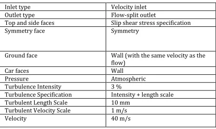
4.2 BOUNDRY CONDITION
Inlet type Velocity inlet Outlet type Flow-split outlet
Top and side faces Slip shear stress specification Symmetry face Symmetry
Ground face Wall (with the same velocity as the flow)
Car faces Wall
Pressure Atmospheric
Turbulence Intensity 3 %
Turbulence Specification Intensity + length scale Turbulent Length Scale 10 mm
Turbulent Velocity Scale 1 m/s
Velocity 40 m/s
TABLE -3 BOUNDARY CONDITION
5. RESULTS AND DISCUSSIONS
Results are last stage but an important one .geometry of our research is too big in volume so the comperation from all numerical value is become too complex and time consuming . so we try to do this based on color contour however it is the second form of numerical values
In our research we had target to complete analysis at five angle of attack and at three speed so whole procedure we can not present here and we presented limited and important results .
Using ANSYS we complete analysis in two parts
© 2017, IRJET | Impact Factor value: 5.181 | ISO 9001:2008 Certified Journal
| Page 1681
(2) analysis of car body using spoiler at various angle of attack and at various height
5.1 PRESSURE COUNTER AT 50M/S
In automotive analysis due to large number of elements and volume it is very complex to take every mathematical data . To save time and reduce complexiblity comparison of color counter is a way to compare down force
FIG-4 EFFECT OF BACK PRESSURE AND IRREGULAR STREAM LINES
FIG-5 EFFECT OF DIFFUSER
© 2017, IRJET | Impact Factor value: 5.181 | ISO 9001:2008 Certified Journal
| Page 1682
FIG-7 PRESSURE CONTOUR AT 50M/S WITHOUT SPOILER
FIG-8 PRESSURE CONTOUR AT 70M/S
© 2017, IRJET | Impact Factor value: 5.181 | ISO 9001:2008 Certified Journal
| Page 1683
FIG-10 GRAPH OF DRAG COEFFICIENT
FIG-11 GRAPH OF COMPARISION OF GRAG AND DOWN FORCE
6. CONCLUSION
In our research we had lots of analysis about 20-30 so it become very complex to conclude bast angle attack for any
speed moreover speed such as 70-80m/s is very higher speed so that analysis should be very exact . At some stage
sych as 30- 40 m/s we required only slip don’t require too much down force . in addition to that we cant focuse
only on down force because at some value down force is high but drag is also high that is why we cannot use that
angal at perticular angal.
At the very high speed down force is very crusial turm also it required to check the streamlines , that should not
creat the back pressure and negative pressure . cfd is dafinately a best way to see aerodynamics however it is too
complex and too much calculation is required with higher order of accuracy so that it can be applied
Although the main goal was to pick the highest value of Lift forces to Drag forces ratio, the absolute values of the
lift forces and drag forces also had to be considered For example, the actual lift was the least of all angle-of- attack
orientations. Hence the end goal was to identify the highest lift possible and then utilize the ratios as a method of
optimization (see Table 3)
© 2017, IRJET | Impact Factor value: 5.181 | ISO 9001:2008 Certified Journal
| Page 1684
Lift:DragRatio 5(degree) 6(degree) 8(degree) 13
degree
150km/hr 8.92 8.87 9.02 9.12
200km/hr 9.06 8.31 7.76 8.91
250km/hr 7.8 7.2 8.32 8.94
TABLE -4 DATA FOR ACTICE SPOILER
7. REFERENCE
1. John J. Bertin, “Aerodynamics for Engineers”, Prentice Hall; 5th edition, New Jersey, June 2008
2. Jiyuan Tu, Guan Heng Yeoh and Chaoqun Liu, “Computational Fluid Dynamics: A Practical Approach”, Butterworth-Heinemann; 1st edition, Burlington, MA, November 2007
3. Oleg Zikanov, “Essential Computational Fluid Dynamics”, John Wiley & Sons, Inc. Hoboken, New Jersey, March 2010
4. C. H. K. Williamson, “Three Dimensional Vortex Dynamics in Bluff Body Wakes”, Experimental Thermal and Fluid Science, Volume 12, February 1996, p. 150-168
5. 1. Wolf-Heinrich Hucho, “Aerodynamics of Road Vehicles: From Fluid Mechanics to Vehicle Engineering”, Society of Automotive Engineers Inc; 4th edition, Warrendale, Pa, February 1998
6. Website: http://autospeed.com/cms/title_Aero-Testing-Part4/A_108676/article.html
7. Marco Lanfrit, “Best practice guidelines for handlingAutomotive External Aerodynamics with FLUENT”, Fluent Deutschland GmbH, 64295 Darmstadt/Germany, February 2005
8. W. Seibert “CFD in Aerodynamic Design Process of Road and Race Cars”, Fluent Deutschland GmbH, FLUENT Technical Notes TN155, Presented at European Automotive Congress, Bratislava, Slovakia, June 18-20 2001
9. Klaus Gersten, E. Krause, H. Jr. Oertel, C. Mayes "Boundary-Layer Theory", Herrmann Schlichting, 8th Edition, Springer 2004 10. W. Seibert, M. Lanfrit, B. Hupertz and L. Krüger “A Best- Practice for High Resolution Aerodynamic Simulation around a Production Car Shape” 4th MIRA International Vehicle Aerodynamics Conference, Warwick, UK, October 16-17, 2002
11. “FLUENT 6.0 User’s Guide - Volume 1”, ANSYS Inc., New York, December 2001.
12. “ANSYS FLUENT 12.0/12.1 in Workbench User's Guide”, ANSYS Inc., New York, October 2011
13. “ANSYS FLUENT 12.0 Theory Guide”, ANSYS Inc., New York, April 2009
14. Masaru KOIKE, Tsunehisa NAGAYOSHI and Naoki HAMAMOTO, “Research on Aerodynamic Drag Reduction by Vortex Generator”, Mitsubishi Motors Technical Reviews, Tokyo, Japan, 2004
15. M. Rouméas, P. Gilliéron & A. Kourta “Drag Reduction by Flow Separation Control on a Car After Body”, Int. J. Numer. Methods Fluids 60, 2008 . ISSN 0271-2091
16. A. Kourta, P. Gilliéron "Impact of the Automotive Aerodynamic Control on the Economic Issues", Journal of Applied Fluid Mechanics , Vol. 2, No. 2, pp. 69-75, 2009, ISSN 1735-3645
17. Byoung-Kwon Lee, MD "Computational Fluid Dynamics in Cardiovascular Disease" Korean Circulation Journal 41(8): 423– 430, August, 2011
18. Website: http://bugattipage.com/ride.htm
19. Website: http://www.nasa.gov/audience/forstudents/5-8/features/what-isaerodynamics-58.html